2006 DODGE RAM SRT-10 key
[x] Cancel search: keyPage 2298 of 5267
RELAY - FUEL PUMP
DESCRIPTION
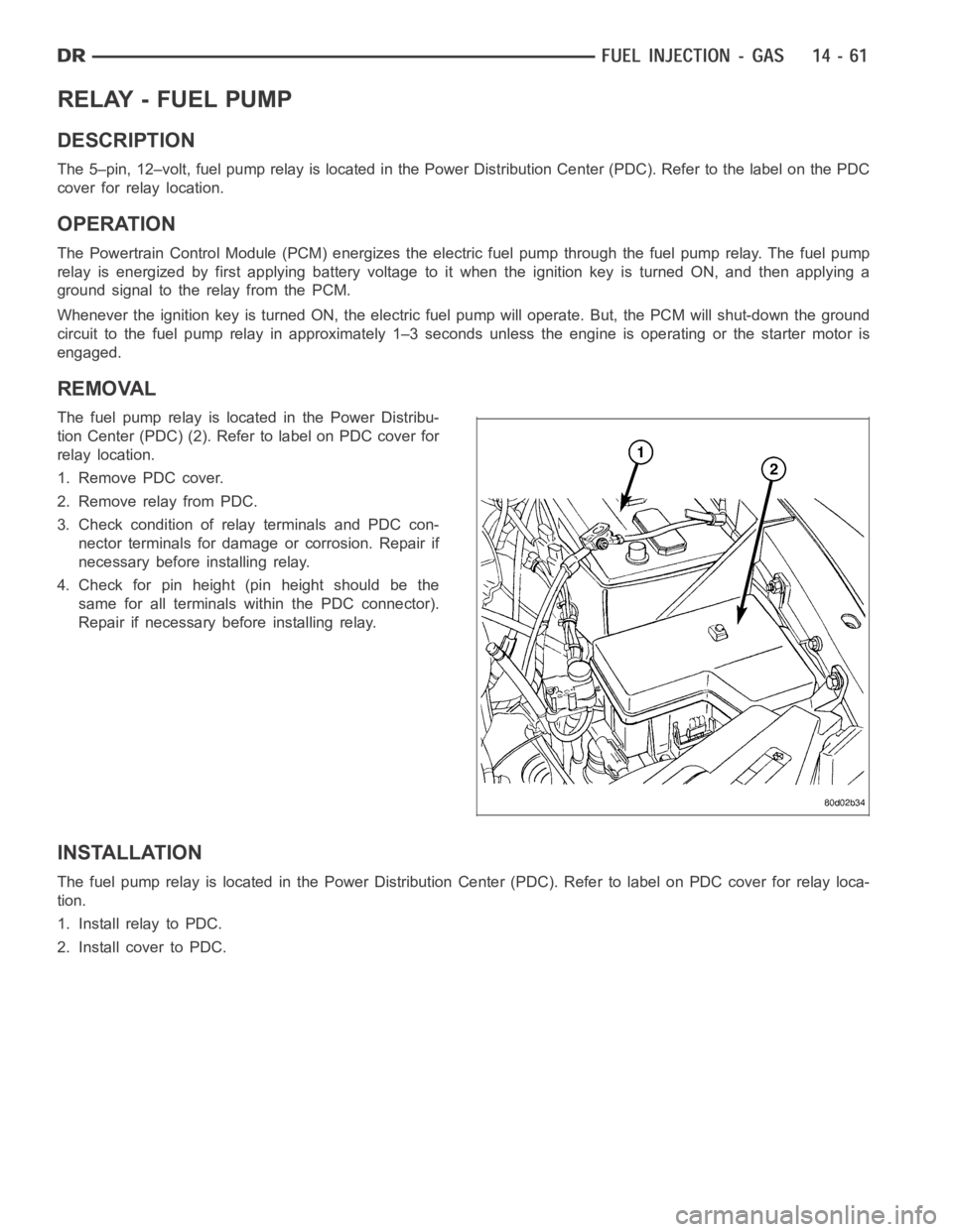
The 5–pin, 12–volt, fuel pump relay is located in the Power Distribution Center (PDC). Refer to the label on the PDC
cover for relay location.
OPERATION
The Powertrain Control Module (PCM) energizes the electric fuel pump through the fuel pump relay. The fuel pump
relay is energized by first applying battery voltage to it when the ignition key is turned ON, and then applying a
ground signal to the relay from the PCM.
Whenever the ignition key is turned ON, the electric fuel pump will operate. But, the PCM will shut-down the ground
circuit to the fuel pump relay in approximately 1–3 seconds unless the engine is operating or the starter motor is
engaged.
REMOVAL
The fuel pump relay is located in the Power Distribu-
tion Center (PDC) (2). Refer to label on PDC cover for
relay location.
1. Remove PDC cover.
2. Remove relay from PDC.
3. Check condition of relay terminals and PDC con-
nector terminals for damage or corrosion. Repair if
necessary before installing relay.
4. Check for pin height (pin height should be the
same for all terminals within the PDC connector).
Repair if necessary before installing relay.
INSTALLATION
The fuel pump relay is located in the Power Distribution Center (PDC). Refer to label on PDC cover for relay loca-
tion.
1. Install relay to PDC.
2. Install cover to PDC.
Page 2300 of 5267
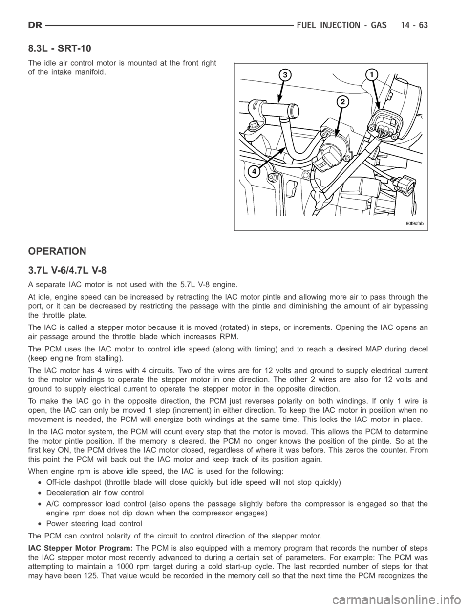
8.3L - SRT-10
The idle air control motor is mounted at the front right
of the intake manifold.
OPERATION
3.7L V-6/4.7L V-8
A separate IAC motor is not used with the 5.7L V-8 engine.
At idle, engine speed can be increased by retracting the IAC motor pintle and allowing more air to pass through the
port, or it can be decreased by restricting the passage with the pintle and diminishing the amount of air bypassing
the throttle plate.
The IAC is called a stepper motor because it is moved (rotated) in steps, or increments. Opening the IAC opens an
air passage around the throttle blade which increases RPM.
The PCM uses the IAC motor to control idle speed (along with timing) and to reach a desired MAP during decel
(keep engine from stalling).
The IAC motor has 4 wires with 4 circuits. Two of the wires are for 12 volts andground to supply electrical current
to the motor windings to operate the stepper motor in one direction. The other2wiresarealsofor12voltsand
ground to supply electrical current to operate the stepper motor in the opposite direction.
To make the IAC go in the opposite direction, the PCM just reverses polarityon both windings. If only 1 wire is
open, the IAC can only be moved 1 step (increment) in either direction. To keeptheIACmotorinpositionwhenno
movement is needed, the PCM will energize both windings at the same time. This locks the IAC motor in place.
In the IAC motor system, the PCM will count every step that the motor is moved. This allows the PCM to determine
the motor pintle position. If the memory is cleared, the PCM no longer knowsthe position of the pintle. So at the
first key ON, the PCM drives the IAC motor closed, regardless of where it wasbefore. This zeros the counter. From
this point the PCM will back out the IAC motor and keep track of its position again.
When engine rpm is above idle speed, the IAC is used for the following:
Off-idle dashpot (throttle blade will close quickly but idle speed will notstopquickly)
Deceleration air flow control
A/C compressor load control (also opens the passage slightly before the compressor is engaged so that the
engine rpm does not dip down when the compressor engages)
Power steering load control
The PCM can control polarity of the circuit to control direction of the stepper motor.
IAC Stepper Motor Program:The PCM is also equipped with a memory program that records the number of steps
the IAC stepper motor most recently advanced to during a certain set of parameters. For example: The PCM was
attempting to maintain a 1000 rpm target during a cold start-up cycle. The last recorded number of steps for that
may have been 125. That value would be recorded in the memory cell so that thenext time the PCM recognizes the
Page 2307 of 5267
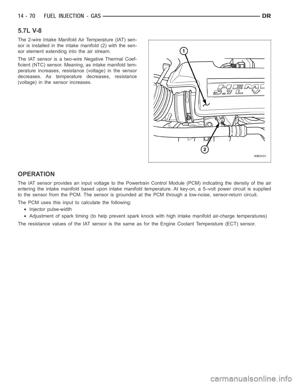
5.7L V-8
The 2-wire Intake Manifold Air Temperature (IAT) sen-
sor is installed in the intake manifold (2) with the sen-
sor element extending into the air stream.
The IAT sensor is a two-wire Negative Thermal Coef-
ficient (NTC) sensor. Meaning, as intake manifold tem-
perature increases, resistance (voltage) in the sensor
decreases. As temperature decreases, resistance
(voltage) in the sensor increases.
OPERATION
The IAT sensor provides an input voltage to the Powertrain Control Module (PCM) indicating the density of the air
entering the intake manifold based upon intake manifold temperature. At key-on, a 5–volt power circuit is supplied
to the sensor from the PCM. The sensor is grounded at the PCM through a low-noise, sensor-return circuit.
The PCM uses this input to calculate the following:
Injector pulse-width
Adjustment of spark timing (to help prevent spark knock with high intake manifold air-charge temperatures)
The resistance values of the IAT sensor is the same as for the Engine CoolantTemperature (ECT) sensor.
Page 2315 of 5267
higher altitude, because the air density changes with altitude. It will also help to correct for varying barometric pres-
sure. Barometric pressure and altitude have a direct inverse correlation; as altitude goes up, barometric goes down.
At key-on, the PCM powers up and looks at MAP voltage, and based upon the voltage it sees, it knows the current
barometric pressure (relative to altitude). Once the engine starts, the PCM looks at the voltage again, continuously
every 12 milliseconds, and compares the current voltage to what it was at key-on. The difference between current
voltage and what it was at key-on, is manifold vacuum.
During key-on (engine not running) the sensor reads (updates) barometricpressure. A normal range can be
obtained by monitoring a known good sensor.
As the altitude increases, the air becomes thinner (less oxygen). If a vehicleisstartedanddriventoaverydifferent
altitude than where it was at key-on, the barometric pressure needs to be updated. Any time the PCM sees Wide
Open Throttle (WOT), based upon Throttle Position Sensor (TPS) angle and RPM, it will update barometric pressure
in the MAP memory cell. With periodic updates, the PCM can make its calculations more effectively.
The PCM uses the MAP sensor input to aid in calculating the following:
Manifold pressure
Barometric pressure
Engine load
Injector pulse-width
Spark-advance programs
Shift-point strategies (certain automatic transmissions only)
Idle speed
Decel fuel shutoff
The MAP sensor signal is provided from asingle piezoresistive element located in the center of a diaphragm. The
element and diaphragm are both made ofsilicone. As manifold pressure changes, the diaphragm moves causing
the element to deflect, which stresses the silicone. When silicone is exposed to stress, its resistance changes. As
manifold vacuum increases, the MAP sensor input voltage decreases proportionally. The sensor also contains elec-
tronics that condition the signal and provide temperature compensation.
The PCM recognizes a decrease in manifold pressure by monitoring a decrease in voltage from the reading stored
in the barometric pressure memory cell. The MAP sensor is a linear sensor; meaning as pressure changes, voltage
changes proportionately. The range of voltage output from the sensor is usually between 4.6 volts at sea level to as
low as 0.3 volts at 26 in. of Hg. Barometric pressure is the pressure exertedby the atmosphere upon an object. At
sea level on a standard day, no storm, barometric pressure is approximately 29.92 in Hg. For every 100 feet of
altitude, barometric pressure drops 0.10 in. Hg. If a storm goes through, it can change barometric pressure from
what should be present for that altitude. You should know what the average pressure and corresponding barometric
pressure is for your area.
Page 2343 of 5267
Fuel enters the system from the electric fuel transfer (lift) pump, which is located inside of the fuel tank and attached
to the fuel tank module (the fuel transfer pump is no longer attached to the engine). Fuel is forced through the fuel
filter element and then enters the Fuel Pump/Gear Pump, which is attached to the rear of the fuel injection pump.
The Fuel Pump/Gear Pump is a low-pressure pump and produce pressures ranging from 551.5 kpa (80 psi) to 1241
kpa (180) psi. Fuel then enters the fuel injection pump. Low pressure fuel is then supplied to the FCA (Fuel Control
Actuator).
The FCA is an electronically controlled solenoid valve. The ECM controls the amount of fuel that enters the high-
pressure pumping chambers by opening and closing the FCA based on a demanded fuel pressure. The FPS (Fuel
Pressure Sensor) on the fuel rail monitors the actual fuel pressure and provides it as an input to the ECM. When
the actuator is opened, the maximum amount of fuel is being supplied to the fuel injection pump. Any fuel that does
not enter the injection pump is directed to the overflow valve. The overflow valve regulates how much excess fuel
is used for lubrication of the pump and how much is returned to the tank through the drain manifold.
Fuel entering the injection pump is pressurized to between 300-1600 bar (4351-23,206 psi) by three radial pumping
chambers. The pressurized fuel is then supplied to the fuel rail.
STANDARD PROCEDURE
WATER DRAINING AT FUEL FILTER
Refer to Fuel Filter/Water Separatorremoval/installation for procedures.
CLEANING FUEL SYSTEM PARTS
CAUTION: Cleanliness cannot be overemphasized when handling or replacingdieselfuelsystemcompo-
nents. This especially includes the fuel injectors, high-pressure fuel lines and fuel injection pump. Very tight
tolerances are used with these parts. Dirt contamination could cause rapid part wear and possible plugging
of fuel injector nozzle tip holes. This in turn could lead to possible engine misfire. Always wash/clean any
fuel system component thoroughly before disassembly and then air dry. Capor cover any open part after
disassembly. Before assembly, examine each part for dirt, grease or othercontaminants and clean if nec-
essary. When installing new parts, lubricate them with clean engine oil orclean diesel fuel only.
FUEL SYSTEM PRIMING
A certain amount of air becomes trappedin the fuel system when fuel system components on the supply and/or
high-pressure side are serviced or replaced. Fuel system priming is accomplished using the electric fuel transfer (lift)
pump.
Servicing or replacing fuel system components will not require fuel systempriming.
The fuel transfer (lift) pump is self-priming: When the key is first turnedon (without cranking engine), the pump
operates for approximately 1 to 2 second and then shuts off (Note: When ambient temperatures are cold enough to
cause the intake air heaters to operate, the fuel lift pump will operate during the entire intake air pre-heat cycle).
The pump will also operate for up to 25 seconds after the starter is quickly engaged, and then disengaged without
allowing the engine to start. The pump shuts off immediately if the key is onand the engine stops running.
1. Turn key to CRANK position and quickly release key to ON position before engine starts. This will operate fuel
transfer pump for approximately 25 seconds.
2. Crank engine. If the engine does not start after 25 seconds, turn key to OFF position, and leave it off for at least
5 seconds. Repeat previous step until engine starts.
3. Fuel system priming is now completed.
4. Attempt to start engine. If engine will not start, proceed to following steps.When engine does start, it may run
erratically and be noisy for a few minutes. This is a normal condition.
CAUTION: Do not engage the starter motor for more than 30 seconds at a time. Allow two minutes between
cranking intervals.
5. Perform previous fuel priming procedure steps using fuel transfer pump. Be sure fuel is present at fuel tank.
6. Crank the engine for 30 seconds at a time to allow fuel system to prime.
Page 2348 of 5267
FILTER - FUEL / WATER SEPARATOR
DESCRIPTION
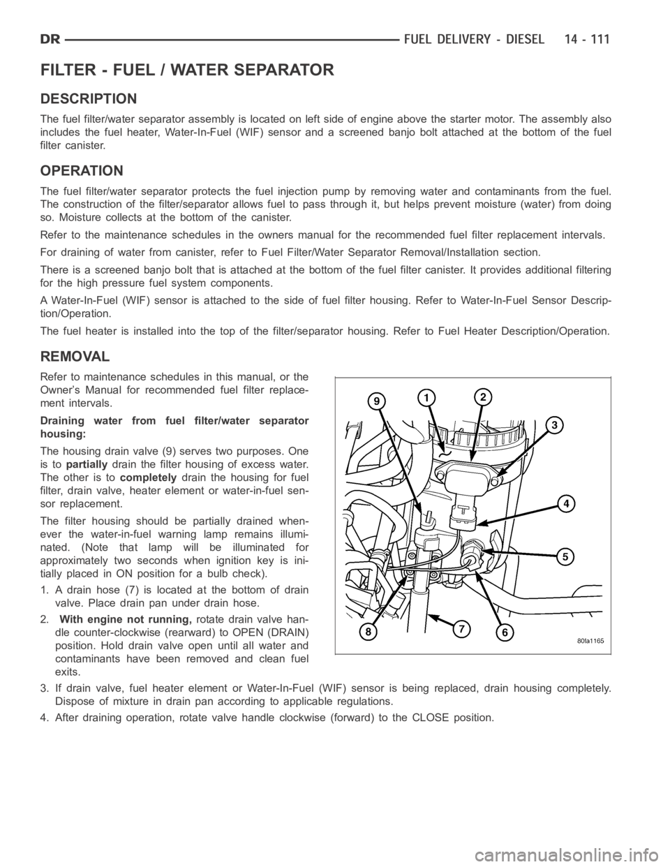
The fuel filter/water separator assembly is located on left side of engineabove the starter motor. The assembly also
includes the fuel heater, Water-In-Fuel (WIF) sensor and a screened banjobolt attached at the bottom of the fuel
filter canister.
OPERATION
The fuel filter/water separator protects the fuel injection pump by removing water and contaminants from the fuel.
The construction of the filter/separator allows fuel to pass through it, but helps prevent moisture (water) from doing
so. Moisture collects at the bottom of the canister.
Refer to the maintenance schedules in the owners manual for the recommended fuel filter replacement intervals.
For draining of water from canister, refer to Fuel Filter/Water SeparatorRemoval/Installation section.
There is a screened banjo bolt that is attached at the bottom of the fuel filter canister. It provides additional filtering
for the high pressure fuel system components.
A Water-In-Fuel (WIF) sensor is attached to the side of fuel filter housing. Refer to Water-In-Fuel Sensor Descrip-
tion/Operation.
The fuel heater is installed into the top of the filter/separator housing.Refer to Fuel Heater Description/Operation.
REMOVAL
Refer to maintenance schedules in this manual, or the
Owner’s Manual for recommended fuel filter replace-
ment intervals.
Draining water from fuel filter/water separator
housing:
The housing drain valve (9) serves two purposes. One
is topartiallydrain the filter housing of excess water.
The other is tocompletelydrain the housing for fuel
filter, drain valve, heater element or water-in-fuel sen-
sor replacement.
The filter housing should be partially drained when-
ever the water-in-fuel warning lamp remains illumi-
nated. (Note that lamp will be illuminated for
approximately two seconds when ignition key is ini-
tially placed in ON position for a bulb check).
1. A drain hose (7) is located at the bottom of drain
valve. Place drain pan under drain hose.
2.With engine not running,rotate drain valve han-
dle counter-clockwise (rearward) to OPEN (DRAIN)
position. Hold drain valve open until all water and
contaminants have been removed and clean fuel
exits.
3. If drain valve, fuel heater element or Water-In-Fuel (WIF) sensor is being replaced, drain housing completely.
Dispose of mixture in drain pan according to applicable regulations.
4. After draining operation, rotate valve handle clockwise (forward) to the CLOSE position.
Page 2357 of 5267
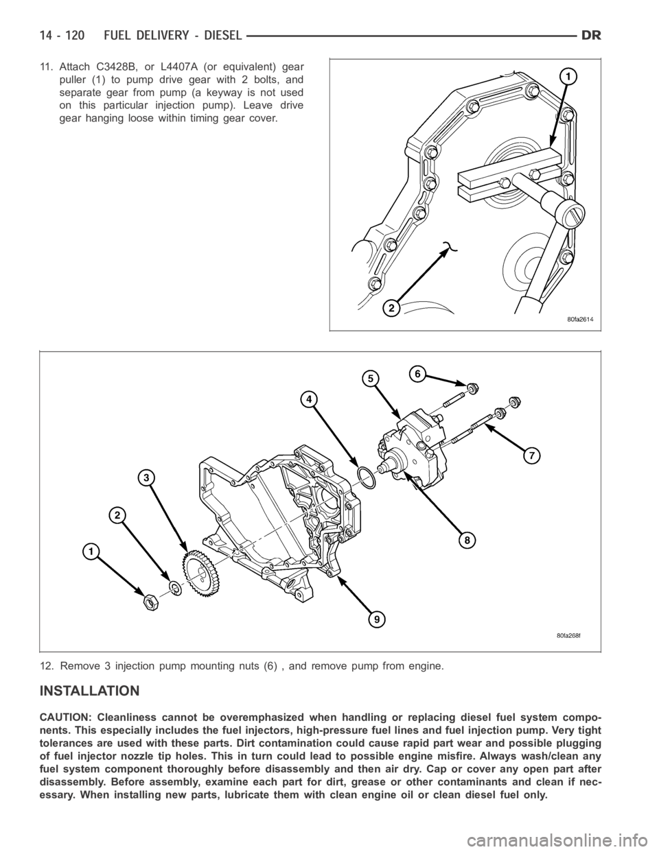
11. Attach C3428B, or L4407A (or equivalent) gear
puller (1) to pump drive gear with 2 bolts, and
separate gear from pump (a keyway is not used
on this particular injection pump). Leave drive
gear hanging loose within timing gear cover.
12. Remove 3 injection pump mounting nuts (6) , and remove pump from engine.
INSTALLATION
CAUTION: Cleanliness cannot be overemphasized when handling or replacingdieselfuelsystemcompo-
nents. This especially includes the fuel injectors, high-pressure fuel lines and fuel injection pump. Very tight
tolerances are used with these parts. Dirt contamination could cause rapid part wear and possible plugging
of fuel injector nozzle tip holes. This in turn could lead to possible engine misfire. Always wash/clean any
fuel system component thoroughly before disassembly and then air dry. Capor cover any open part after
disassembly. Before assembly, examine each part for dirt, grease or othercontaminants and clean if nec-
essary. When installing new parts, lubricate them with clean engine oil orclean diesel fuel only.
Page 2373 of 5267
PUMP - FUEL TRANSFER
DESCRIPTION
The fuel transfer pump (fuel lift pump) is part of the fuel pump module. The fuel pump module is located in the fuel
tank. The 12–volt electric pump is operated and controlled by the Engine Control Module (ECM). The ECM controls
a relay in the Intelligent Power Module(IPM) for transfer pump operation.
OPERATION
The purpose of the fuel transfer pump is to supply (transfer) a low-pressure fuel source:fromthe fuel tank,through
the fuel filter/water separator andtothe fuel injection pump. Here, the low-pressure is raised to a high-pressure by
the fuel injection pump for operation of the high-pressure fuel injectors. Check valves within the pump, control direc-
tion of fuel flow and prevent fuel bleed-back during engine shut down.
Maximum current flow to the pump is 5 amperes.
With the engine running, the pump has a 100 percent duty-cycle.
The transfer pump is self-priming: When the key is first turned on (withoutcranking engine), the pump will operate
for approximately 2 seconds and then shut off (Note: When ambient temperatures are cold enough to cause the
intake air heaters to operate, the fuel lift pump will operate during the entire intake air pre-heat cycle). The pump will
also operate for up to 25 seconds after the starter is engaged, and then disengaged and the engine is not running.
The pump shuts off immediately if the key is on and the engine stops running.
The fuel volume of the transfer pump will always provide more fuel than the fuel injection pump requires. Excess
fuel is returned from the injection pump through an overflow valve, and then back to the fuel tank.
REMOVAL
The fuel transfer pump (fuel lift pump) is a part of the fuel tank module. It is not serviced separately. Refer to Fuel
Tank Module Removal or Installation for procedures (Refer to 14 - FUEL SYSTEM/FUEL DELIVERY/FUEL TANK
MODULE - REMOVAL).
INSTALLATION
The fuel transfer pump (fuel lift pump) is a part of the fuel tank module. It is not serviced separately (Refer to 14 -
FUEL SYSTEM/FUEL DELIVERY/FUEL TANK MODULE - INSTALLATION).