Page 2375 of 5267
SENSOR-WATER IN FUEL
DESCRIPTION
The Water-In-Fuel (WIF) sensor (5) is located on the
side of the fuel filter/water separator canister.
OPERATION
The sensor sends an input to the Engine Control Module (ECM) when it senses water in the fuel filter/water sep-
arator. As the water level in the filter/separator increases, the resistance across the WIF sensor decreases. This
decreaseinresistanceissentasasignaltotheECMandcomparedtoahighwater standard value. Once the value
reaches 30 to 40 kilohms, the ECM will activate the water-in-fuel warning lamp through CCD bus circuits. This all
takes place when the ignition key is initially put in the ON position. The ECM continues to monitor the input while
the engine is running.
REMOVAL
The Water-In-Fuel (WIF) sensor is located at the side of fuel filter/waterseparator canister. (Refer to 14 - FUEL
SYSTEM/FUEL DELIVERY/FUEL TANK MODULE - INSTALLATION).
Page 2384 of 5267
ACTUATOR - FUEL CONTROL
DESCRIPTION
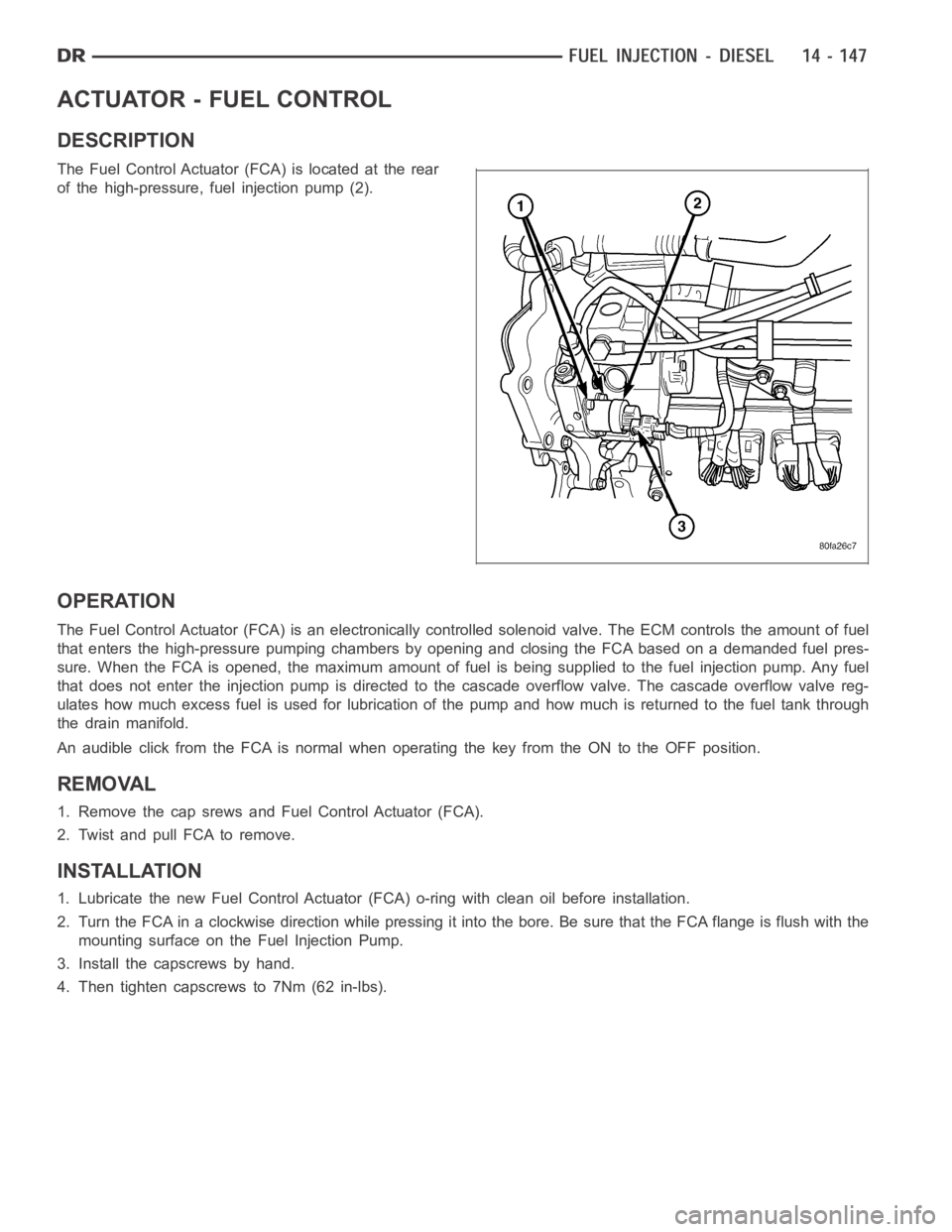
The Fuel Control Actuator (FCA) is located at the rear
of the high-pressure, fuel injection pump (2).
OPERATION
The Fuel Control Actuator (FCA) is an electronically controlled solenoidvalve. The ECM controls the amount of fuel
that enters the high-pressure pumping chambers by opening and closing theFCA based on a demanded fuel pres-
sure. When the FCA is opened, the maximum amount of fuel is being supplied tothe fuel injection pump. Any fuel
that does not enter the injection pump is directed to the cascade overflow valve. The cascade overflow valve reg-
ulates how much excess fuel is used for lubrication of the pump and how much is returned to the fuel tank through
the drain manifold.
An audible click from the FCA is normal when operating the key from the ON to the OFF position.
REMOVAL
1. Remove the cap srews and Fuel Control Actuator (FCA).
2. Twist and pull FCA to remove.
INSTALLATION
1. Lubricate the new Fuel Control Actuator (FCA) o-ring with clean oil before installation.
2. Turn the FCA in a clockwise direction while pressing it into the bore. Be sure that the FCA flange is flush with the
mounting surface on the Fuel Injection Pump.
3. Install the capscrews by hand.
4. Then tighten capscrews to 7Nm (62 in-lbs).
Page 2412 of 5267
page page
COLUMN
DESCRIPTION
DESCRIPTION ............................... 8
DESCRIPTION - SRT10 ....................... 9
DIAGNOSIS AND TESTING
STEERING COLUMN ......................... 9
REMOVAL ..................................... 9
INSTALLATION ............................... 12
SPECIFICATIONS
TORQUE ................................... 14
IGNITION SWITCH
DESCRIPTION ................................ 15
OPERATION .................................. 15
DIAGNOSIS AND TESTING
IGNITION SWITCH .......................... 15
REMOVAL .................................... 16
INSTALLATION ............................... 17
IGNITION SWITCH - SRT10
REMOVAL - SRT10 ............................ 19
INSTALLATION - SRT10 ....................... 21
KEY-IN IGNITION SWITCH
DESCRIPTION ................................ 22
DIAGNOSIS AND TESTING
IGNITION SWITCH AND KEY LOCK
CYLINDER................................. 22KEY CYLINDER
REMOVAL .................................... 23
INSTALLATION ............................... 23
STEERING WHEEL
REMOVAL .................................... 24
INSTALLATION ............................... 24
TILT LEVER KNOB RELEASE
REMOVAL .................................... 25
INSTALLATION ............................... 26
GEAR SHIFT LEVER
REMOVAL .................................... 28
INSTALLATION ............................... 29
UPPER STEERING COUPLING
REMOVAL .................................... 32
INSTALLATION ............................... 33
LOWER STEERING COUPLING
REMOVAL
ALL LD & HD EXCEPT 4X4 HD ............... 34
4X4 HD .................................... 34
INSTALLATION
ALL LD & HD EXCEPT 4X4 HD ............... 36
4X4 HD .................................... 36
Page 2413 of 5267
COLUMN
DESCRIPTION
DESCRIPTION
NOTE: The steering column on vehicles with an automatic transmission may not be equipped with an inter-
nal locking shaft that allows the ignition key cylinder to be locked with the key. Alternative methods of lock-
ing the steering wheel for service will have to be used.
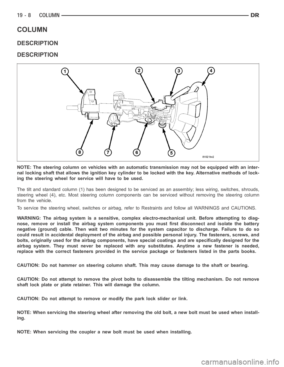
The tilt and standard column (1) has been designed to be serviced as an assembly; less wiring, switches, shrouds,
steering wheel (4), etc. Most steering column components can be serviced without removing the steering column
from the vehicle.
To service the steering wheel, switches or airbag, refer to Restraints andfollow all WARNINGS and CAUTIONS.
WARNING: The airbag system is a sensitive, complex electro-mechanical unit. Before attempting to diag-
nose, remove or install the airbag system components you must first disconnect and isolate the battery
negative (ground) cable. Then wait two minutes for the system capacitor todischarge. Failure to do so
could result in accidental deployment of the airbag and possible personalinjury. The fasteners, screws, and
bolts, originally used for the airbag components, have special coatings and are specifically designed for the
airbag system. They must never be replaced with any substitutes. Anytime anew fastener is needed,
replace with the correct fasteners provided in the service package or fasteners listed in the parts books.
CAUTION: Do not hammer on steering column shaft. This may cause damage to the shaft or bearing.
CAUTION: Do not attempt to remove the pivot bolts to disassemble the tilting mechanism. Do not remove
shaft lock plate or plate retainer. This will damage the column.
CAUTION: Do not attempt to remove or modify the park lock slider or link.
NOTE: When servicing the steering wheel after removing the old bolt, a new bolt must be used when install-
ing.
NOTE: When servicing the coupler a new bolt must be used when installing.
Page 2414 of 5267
DESCRIPTION - SRT10
The SRT-10 column has noSTARTposition on the key cylinder. The push starter button switch is mounted on the
Instrument panel center stack. All SRT-10 columns are Tilt columns, Standard cab trucks come with manual trans-
missions, Quad cab trucks come equipped with automatic transmissions.
DIAGNOSIS AND TESTING
STEERING COLUMN
If the vehicle is involved in a front end collision/the air bag has deployedthe column must be inspected. This
inspection will determine if the Column has collapsed. Inspect the columnmounting capsules visually and manually
push and pull them to check for separation or fractures. If capsules are fractured or have moved the column MUST
be replaced.
REMOVAL
WARNING: Before servicing the steering column the airbag system must be disarmed. Refer to electrical
restraint system for service procedures. Failure to do so may result in accidental deployment of the airbag
and possible personal injury.
CAUTION: All fasteners must be torqued to specification to ensure proper operation of the steering column.
1. Position the front wheelsstraight ahead.
2. Disconnect the negative (ground) cable from the battery.
3. Remove the airbag, (Refer to 8 - ELECTRICAL/RE-
STRAINTS/DRIVER AIRBAG - REMOVAL).
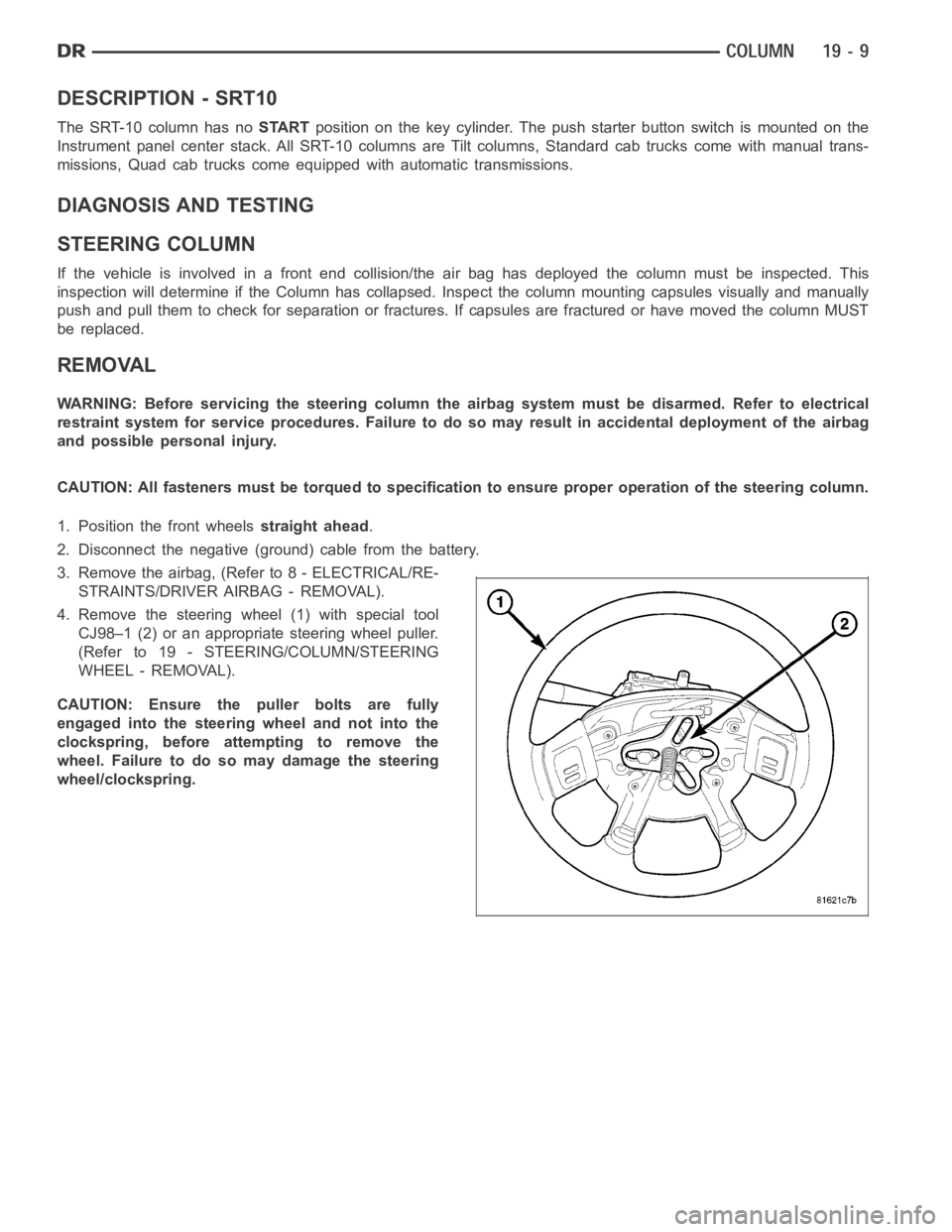
4. Remove the steering wheel (1) with special tool
CJ98–1 (2) or an appropriate steering wheel puller.
(Refer to 19 - STEERING/COLUMN/STEERING
WHEEL - REMOVAL).
CAUTION: Ensure the puller bolts are fully
engaged into the steering wheel and not into the
clockspring, before attempting to remove the
wheel. Failure to do so may damage the steering
wheel/clockspring.
Page 2420 of 5267
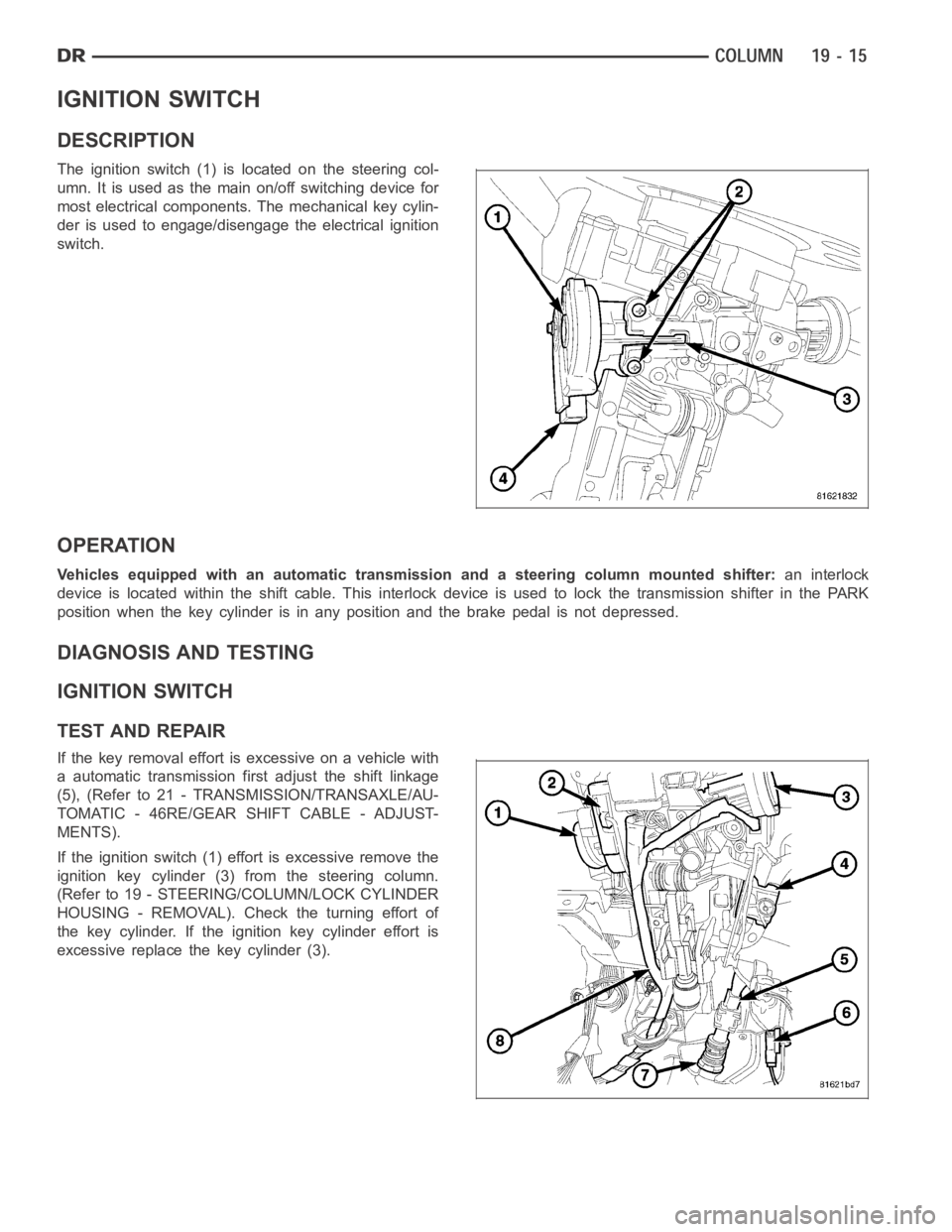
IGNITION SWITCH
DESCRIPTION
The ignition switch (1) is located on the steering col-
umn. It is used as the main on/off switching device for
most electrical components. The mechanical key cylin-
der is used to engage/disengage the electrical ignition
switch.
OPERATION
Vehicles equipped with an automatic transmission and a steering column mounted shifter:an interlock
device is located within the shift cable. This interlock device is used to lock the transmission shifter in the PARK
position when the key cylinder is in any position and the brake pedal is not depressed.
DIAGNOSIS AND TESTING
IGNITION SWITCH
TEST AND REPAIR
If the key removal effort is excessive on a vehicle with
a automatic transmission first adjust the shift linkage
(5), (Refer to 21 - TRANSMISSION/TRANSAXLE/AU-
TOMATIC - 46RE/GEAR SHIFT CABLE - ADJUST-
MENTS).
If the ignition switch (1) effort is excessive remove the
ignition key cylinder (3) from the steering column.
(Refer to 19 - STEERING/COLUMN/LOCK CYLINDER
HOUSING - REMOVAL). Check the turning effort of
the key cylinder. If the ignition key cylinder effort is
excessive replace the key cylinder (3).
Page 2421 of 5267
REMOVAL
SERVICE PRECAUTIONS
NOTE: The steering column on vehicles equipped with an automatic transmission is not equipped with an
internal locking shaft with the ignition cylinder. Alternative methods of locking the steering wheel for ser-
vice will have to be used.
To service the steering wheel, switches or airbag, Refer to Electrical Restraints and follow all WARNINGS and CAU-
TIONS.
WARNING: The airbag system is a sensitive, complex electro-mechanical unit. Before attempting to diag-
nose, remove or install the airbag system components you must first disconnect and isolate the battery
negative (ground) cable. Then wait two minutes for the system capacitor todischarge. Failure to do so
could result in accidental deployment of the airbag and possible personalinjury. The fasteners, screws, and
bolts, originally used for the airbag components, have special coatings and are specifically designed for the
airbag system. They must never be replaced with any substitutes. Anytime anew fastener is needed,
replace with the correct fasteners provided in the service package or fasteners listed in the parts books.
CAUTION: Do not hammer on steering column shaft. This may cause damage to the shaft or bearing.
CAUTION: Do not attempt to remove the pivot bolts to disassemble the tilting mechanism.
The ignition key must be in the key cylinder for cylinder removal. The key cylinder must be removed first before
removing ignition switch.
1. Remove the negative (ground) cable from the battery.
2. Disable the airbag, (Refer to 8 - ELECTRICAL/RESTRAINTS/DRIVER AIRBAG- REMOVAL).
3. Remove the kneeblocker and steering column reinforcement panel.
4. Remove the lower and upper shrouds.
5. Remove key cylinder. (Refer to 19 - STEERING/COLUMN/LOCK CYLINDER HOUSING - REMOVAL).
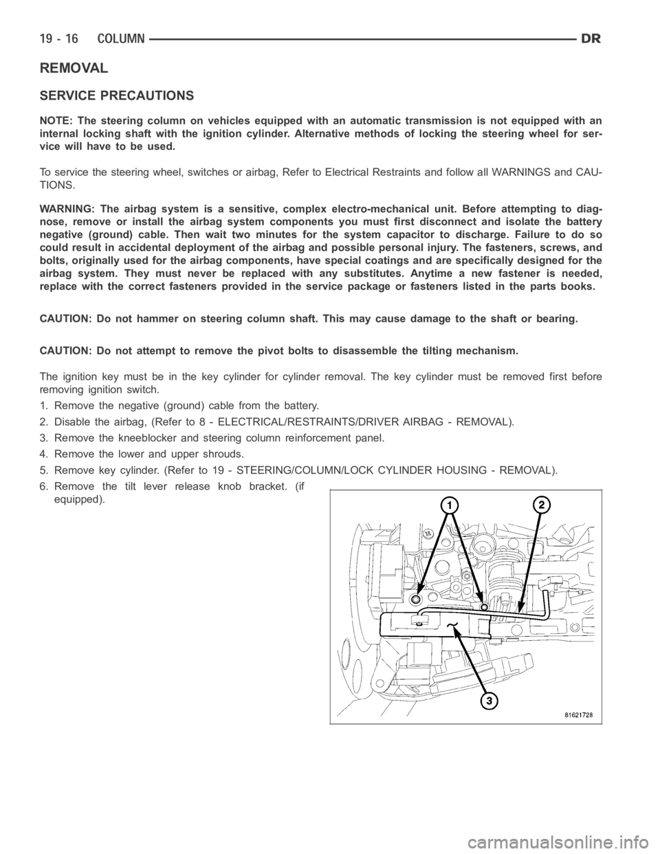
6. Remove the tilt lever release knob bracket. (if
equipped).
Page 2422 of 5267
7. Disconnect the electrical connector at rear of igni-
tion switch (4).
8. Remove ignition switch mounting screws (2).
9. Using a small screwdriver, push on locking tab (3)
and remove switch (1) from steering column.
INSTALLATION
The ignition key must be in the key cylinder for cylinder installation. Thekey cylinder must be removed first before
installing ignition switch.
1. Before installing ignitionswitch (1), rotate the slot
in the switch to the ON position.
2. Position switch (1) to column and install the mount-
ing screws (2). Tighten screw to 3 Nꞏm (26 in. lbs.).
3. Connect the electrical connector to rear of the igni-
tion switch (4). Make sure that locking tabs are fully
seated into wiring connector.