Page 1578 of 5267
INSTALLATION
CAUTION: To prevent severe damage to the Crank-
shaft, Damper or Special Tool 8512–A, thoroughly
clean the damper bore and the crankshaft nose
before installing Damper.
1. Align crankshaft damper slot with key in crankshaft.
Slide damper onto crankshaft slightly.
CAUTION: Special Tool 8512–A, is assembled in a
specific sequence. Failure to assemble this tool in
this sequence can result in tool failure and severe
damage to either the tool or the crankshaft.
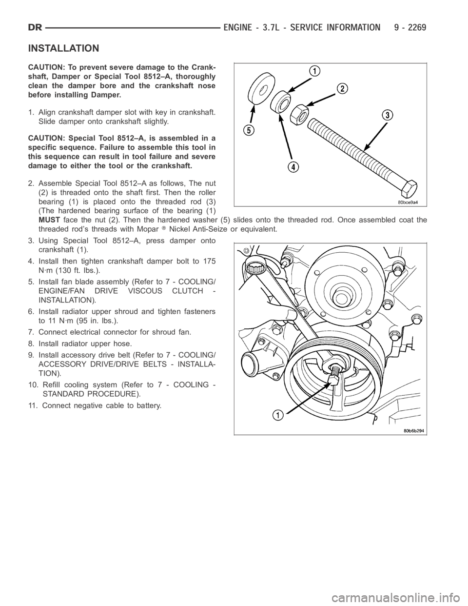
2. Assemble Special Tool 8512–A as follows, The nut
(2) is threaded onto the shaft first. Then the roller
bearing (1) is placed onto the threaded rod (3)
(The hardened bearing surface of the bearing (1)
MUSTface the nut (2). Then the hardened washer (5) slides onto the threaded rod.Once assembled coat the
threaded rod’s threads with Mopar
Nickel Anti-Seize or equivalent.
3. Using Special Tool 8512–A, press damper onto
crankshaft (1).
4. Install then tighten crankshaft damper bolt to 175
Nꞏm (130 ft. lbs.).
5. Install fan blade assembly (Refer to 7 - COOLING/
ENGINE/FAN DRIVE VISCOUS CLUTCH -
INSTALLATION).
6. Install radiator upper shroud and tighten fasteners
to 11 Nꞏm (95 in. lbs.).
7. Connect electrical connector for shroud fan.
8. Install radiator upper hose.
9. Install accessory drive belt (Refer to 7 - COOLING/
ACCESSORY DRIVE/DRIVE BELTS - INSTALLA-
TION).
10. Refill cooling system (Refer to 7 - COOLING -
STANDARD PROCEDURE).
11. Connect negative cable to battery.
Page 1713 of 5267
INSTALLATION
CAUTION: To prevent severe damage to the Crank-
shaft, Damper or Special Tool 8512–A, thoroughly
clean the damper bore and the crankshaft nose
before installing Damper.
1. Align crankshaft damper slot with key in crankshaft.
Slide damper onto crankshaft slightly.
CAUTION: Special Tool 8512–A, is assembled in a
specific sequence. Failure to assemble this tool in
this sequence can result in tool failure and severe
damage to either the tool or the crankshaft.
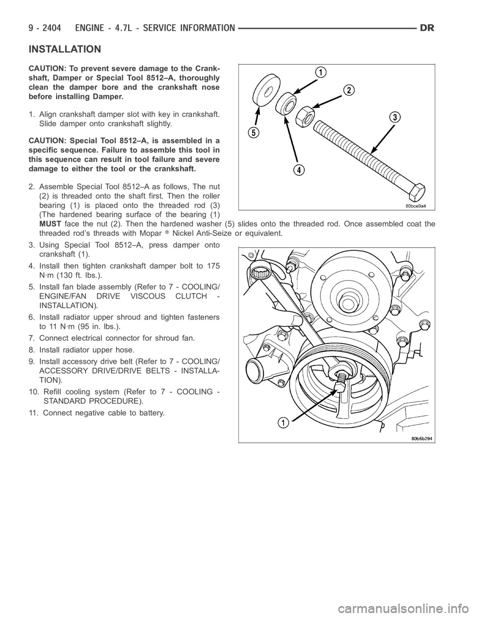
2. Assemble Special Tool 8512–A as follows, The nut
(2) is threaded onto the shaft first. Then the roller
bearing (1) is placed onto the threaded rod (3)
(The hardened bearing surface of the bearing (1)
MUSTface the nut (2). Then the hardened washer (5) slides onto the threaded rod.Once assembled coat the
threaded rod’s threads with Mopar
Nickel Anti-Seize or equivalent.
3. Using Special Tool 8512–A, press damper onto
crankshaft (1).
4. Install then tighten crankshaft damper bolt to 175
Nꞏm (130 ft. lbs.).
5. Install fan blade assembly (Refer to 7 - COOLING/
ENGINE/FAN DRIVE VISCOUS CLUTCH -
INSTALLATION).
6. Install radiator upper shroud and tighten fasteners
to 11 Nꞏm (95 in. lbs.).
7. Connect electrical connector for shroud fan.
8. Install radiator upper hose.
9. Install accessory drive belt (Refer to 7 - COOLING/
ACCESSORY DRIVE/DRIVE BELTS - INSTALLA-
TION).
10. Refill cooling system (Refer to 7 - COOLING -
STANDARD PROCEDURE).
11. Connect negative cable to battery.
Page 1896 of 5267
TIMING CHAIN & SPROCKETS
REMOVAL
1. Disconnect battery negative cable.
2. Drain cooling system.
3. Remove Timing Chain Cover (1).
4. Re-install the vibration damper bolt finger tight.
Using a suitable socket and breaker bar, rotate the
crankshaft to align timing chain sprockets and key-
ways as shown.
CAUTION: The camshaft pin and the slot in the
cam sprocket must be clocked at 12:00 (2). The
crankshaft keyway must be clocked at 2:00 (3).
The crankshaft sprocket must be installed so that
the dots and or paint marking is at 6:00.
Page 1899 of 5267
INSTALLATION
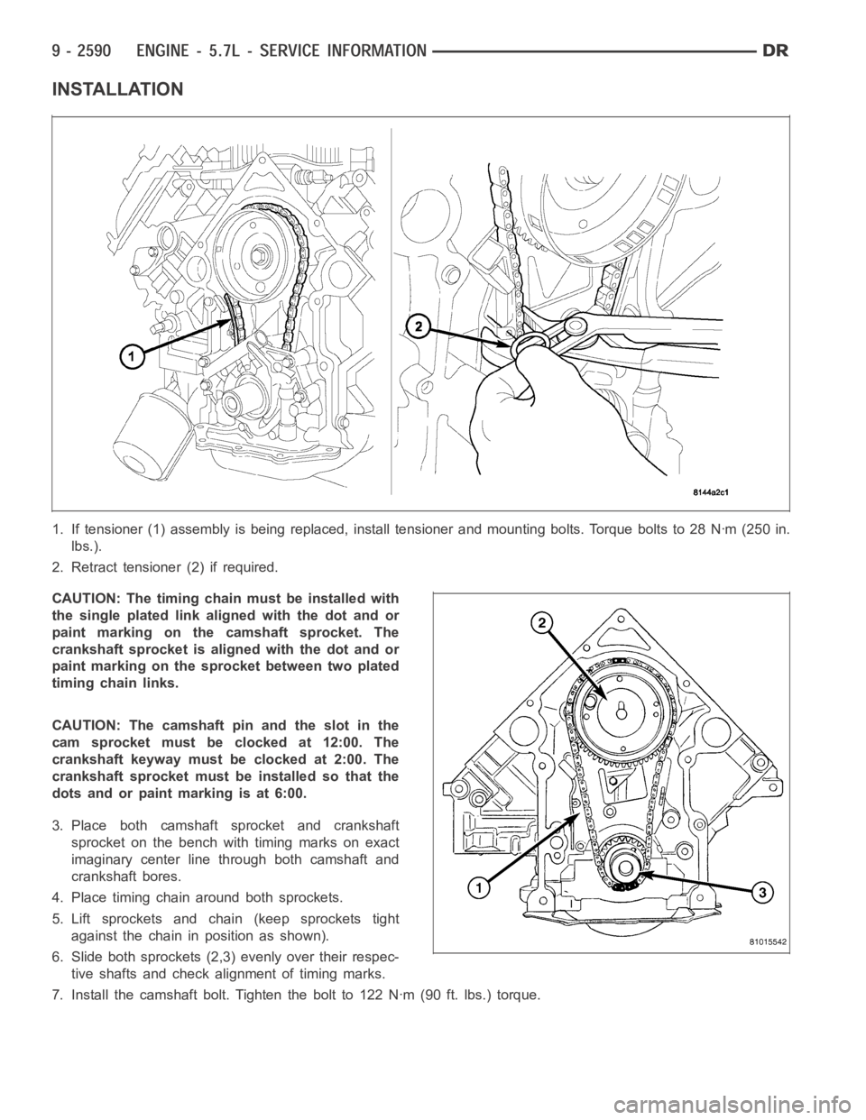
1. If tensioner (1) assembly is being replaced, install tensioner and mounting bolts. Torque bolts to 28 Nꞏm (250 in.
lbs.).
2. Retract tensioner (2) if required.
CAUTION: The timing chainmust be installed with
the single plated link aligned with the dot and or
paint marking on the camshaft sprocket. The
crankshaft sprocket is aligned with the dot and or
paint marking on the sprocket between two plated
timing chain links.
CAUTION: The camshaft pin and the slot in the
cam sprocket must be clocked at 12:00. The
crankshaft keyway must be clocked at 2:00. The
crankshaft sprocket must be installed so that the
dots and or paint marking is at 6:00.
3. Place both camshaft sprocket and crankshaft
sprocket on the bench with timing marks on exact
imaginary center line through both camshaft and
crankshaft bores.
4. Place timing chain around both sprockets.
5. Lift sprockets and chain (keep sprockets tight
against the chain in position as shown).
6. Slide both sprockets (2,3) evenly over their respec-
tive shafts and check alignment of timing marks.
7. Install the camshaft bolt. Tighten the bolt to 122 Nꞏm (90 ft. lbs.) torque.
Page 1986 of 5267
PISTON & CONNECTING ROD
DESCRIPTION
PISTONS
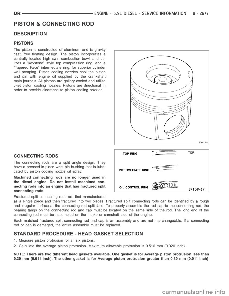
The piston is constructed of aluminum and is gravity
cast, free floating design. The piston incorporates a
centrally located high swirl combustion bowl, and uti-
lizes a “keystone” style top compression ring, and a
“Tapered Face” intermediate ring, for superior cylinder
wall scraping. Piston cooling nozzles cool the piston
and pin with engine oil supplied by the crankshaft
main journals. All pistons are gallery cooled and utilize
J-jet piston cooling nozzles. Pistons are directional in
order to provide clearance to piston cooling nozzles.
CONNECTING RODS
The connecting rods are a split angle design. They
have a pressed-in-place wrist pin bushing that is lubri-
cated by piston cooling nozzle oil spray.
Machined connecting rods are no longer used in
the diesel engine. Do not install machined con-
necting rods into an engine that has fractured split
connecting rods.
Fractured split connecting rods are first manufactured
asasinglepieceandthenfracturedintotwopieces.Fracturedsplitconnecting rods can be identified by a rough
and irregular surface at the connecting rod split face. To properly assemble the rod cap to the connecting rod, the
bearing tangs on the connecting rod and cap must be located on the same side of the rod. The long end of the
connecting rod must be assembled on theintake or camshaft side of the engine.
Each matched fractured split connecting rod and cap is an assembly and are not interchangeable. If a connecting
rod or cap is damaged, the entire assembly must be replaced.
STANDARD PROCEDURE - HEAD GASKET SELECTION
1. Measure piston protrusion for all six pistons.
2. Calculate the average piston protrusion. Maximum allowable protrusion is 0.516 mm (0.020 inch).
NOTE: There are two different head gaskets available. One gasket is for Average piston protrusion less than
0.30 mm (0.011 inch). The other gasket is for Average piston protrusion greater than 0.30 mm (0.011 inch)
Page 2015 of 5267
VALVE TIMING
STANDARD PROCEDURE - TIMING VERIFICATION
1. Remove the cylinder head cover (Refer to 9 - ENGINE/CYLINDER HEAD/CYLINDER HEAD COVER(S) -
REMOVAL).
2. Remove fuel injector from cylindernumber 1 (Refer to 14 - FUEL SYSTEM/FUEL INJECTION/FUEL INJECTOR
- REMOVAL).
3. Using Special Tool 7471B rotate the engine until the TDC mark on the damper is at 12 o’clock.
4. Using a 8 in.x 1/4 in. dowel rod inserted into cylinder number 1, rock the crankshaft back and forth to verify
piston number 1 is at TDC.
5. With cylinder number still at TDC, inspect the keyway on the crankshaft gear for proper alignment (12 o’clock
position).
6. If the keyway is not at 12 o’clock position replace the crankshaft gear assembly.
7. If the keyway is at 12 o’clock position, remove front gear cover and verify timing mark alignment between the
camshaft gear and crankshaft gear, if not aligned inspect keyway on camshaft gear.
8. Inspect keyway on camshaft gear for proper alignment with the key in the camshaft, if alignment is off replace
the camshaft/gear assembly.
9. If timing marks alignment is off and no damage is found at either the crankshaft or camshaft gear keyways,
realign timing marks as necessary.
Page 2084 of 5267
2. Using Special Tools 9056 (1) and 5048 (2 and 3),
remove crankshaft sprocket.
INSTALLATION
CRANKSHAFT SPROCKET INSTALLATION
1. Position a new crankshaft sprocket on the crank-
shaft with timing mark facing out. Align crankshaft
keyway with slot in crankshaft sprocket.
NOTE: Lubricate the threads of Special Tool 9055
(1) using Mopar
Nickel Anti-seize Compound or
equivalent, before beginning crankshaft sprocket
installation.
2. Install the crankshaft sprocket using Special Tool
9055 (1).
Page 2241 of 5267
OPERATION
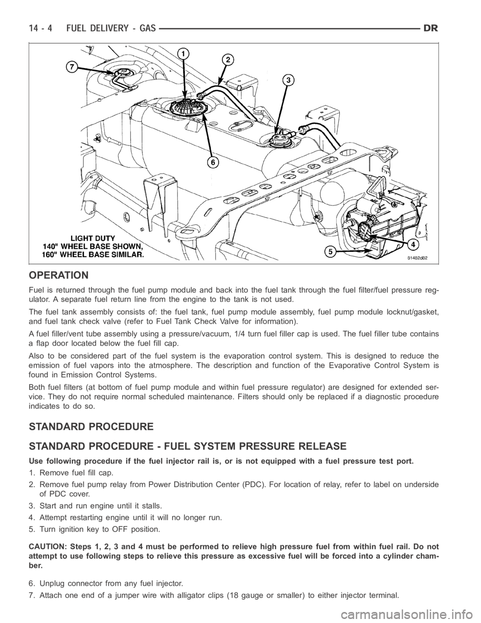
Fuel is returned through the fuel pump module and back into the fuel tank through the fuel filter/fuel pressure reg-
ulator. A separate fuel return line from the engine to the tank is not used.
The fuel tank assembly consists of: the fuel tank, fuel pump module assembly, fuel pump module locknut/gasket,
and fuel tank check valve (refer to Fuel Tank Check Valve for information).
A fuel filler/vent tube assembly using apressure/vacuum,1/4 turn fuel filler cap is used. The fuel filler tube contains
a flap door located below the fuel fill cap.
Also to be considered part of the fuelsystem is the evaporation control system. This is designed to reduce the
emission of fuel vapors into the atmosphere. The description and functionof the Evaporative Control System is
found in Emission Control Systems.
Both fuel filters (at bottom of fuel pump module and within fuel pressure regulator) are designed for extended ser-
vice. They do not require normal scheduled maintenance. Filters should only be replaced if a diagnostic procedure
indicates to do so.
STANDARD PROCEDURE
STANDARD PROCEDURE - FUEL SYSTEM PRESSURE RELEASE
Use following procedure if the fuel injector rail is, or is not equipped with a fuel pressure test port.
1. Remove fuel fill cap.
2. Remove fuel pump relay from Power Distribution Center (PDC). For location of relay, refer to label on underside
of PDC cover.
3. Start and run engine until it stalls.
4. Attempt restarting engine until it will no longer run.
5. Turn ignition key to OFF position.
CAUTION: Steps 1, 2, 3 and 4 must be performed to relieve high pressure fuel from within fuel rail. Do not
attempt to use following steps to relieve this pressure as excessive fuel will be forced into a cylinder cham-
ber.
6. Unplug connector from any fuel injector.
7. Attach one end of a jumper wire with alligator clips (18 gauge or smaller)to either injector terminal.