2006 DODGE RAM SRT-10 key
[x] Cancel search: keyPage 3869 of 5267
OPERATION
Compensation is required for performance variations of two of the input devices. Though the slope of the transfer
functions is tightly controlled, offset may vary due to various environmental factors or manufacturing tolerances.
The pressure transducer is affected by barometric pressure as well as temperature. Calibration of the zero pressure
offset is required to compensate for shifting output due to these factors.
Normal calibration will be performed when sump temperature is above 50 degrees F, or in the absence of sump
temperature data, after the first 10 minutes of vehicle operation. Calibration of the pressure transducer offset occurs
each time the output shaft speed falls below 200 RPM. Calibration shall be repeated each 3 seconds the output
shaft speed is below 200 RPM. A 0.5 second pulse of 95% duty cycle is applied to the governor pressure solenoid
valve and the transducer output is read during this pulse. Averaging of thetransducer signal isnecessary to reject
electrical noise.
Under cold conditions (below 50 degrees F sump), the governor pressure solenoid valve response may be too slow
to guarantee 0 psi during the 0.5 second calibration pulse. Calibration pulses are continued during this period, how-
ever the transducer output valves are discarded. Transducer offset must be read at key-on, under conditions which
promote a stable reading. This value is retained and becomes the offset during the
coldperiod of operation.
GOVERNOR PRESSURE SOLENOID VALVE
The inlet side of the solenoid valve is exposed to normal transmission linepressure. The outlet side of the valve
leads to the valve body governor circuit.
The solenoid valve regulates line pressure to produce governor pressure.Theaveragecurrentsuppliedtothesole-
noid controls governor pressure. One amp current produces zero kPa/psi governor pressure. Zero amps sets the
maximum governor pressure.
The powertrain control module (PCM) turns on the trans control relay whichsupplies electrical power to the solenoid
valve. Operating voltage is 12 volts (DC). The PCM controls the ground sideof the solenoid using the governor
pressure solenoidcontrol circuit.
GOVERNOR PRESSURE SENSOR
The sensor output signal provides the necessary feedback to the PCM. This feedback is needed to adequately
control governor pressure.
GOVERNOR BODY AND TRANSFER PLATE
The transfer plate channels line pressure to the solenoid valve through the governor body. It also channels governor
pressure from the solenoid valve to the governor circuit. It is the solenoid valve that develops the necessary gov-
ernor pressure.
GOVERNOR PRESSURE CURVES
LOW TRANSMISSION FLUID TEMPERATURE
When the transmission fluid is cold the conventional governor can delay shifts, resulting in higher than normal shift
speeds and harsh shifts. The electronically controlled low temperature governor pressure curve is higher than nor-
mal to make the transmission shift at normal speeds and sooner. The PCM usesa temperature sensor in the trans-
mission oil sump to determine when low temperature governor pressure is needed.
NORMAL OPERATION
Normal operation is refined through the increased computing power of the PCM and through access to data on
engine operating conditions provided by the PCM that were not available with the previous stand-alone electronic
module. This facilitated the development of a load adaptive shift strategy - the ability to alter the shift schedule in
response to vehicle load condition. One manifestation of this capabilityis grade
huntingprevention - the ability of
the transmission logic to delay an upshift on a grade if the engine does not have sufficient power to maintain speed
in the higher gear. The 3-2 downshift and the potential for hunting betweengears occurs with a heavily loaded
vehicle or on steep grades. When hunting occurs, it is very objectionable because shifts are frequent and accom-
panied by large changes in noise and acceleration.
Page 3949 of 5267
ADJUSTMENTS - THROTTLE VALVE CABLE
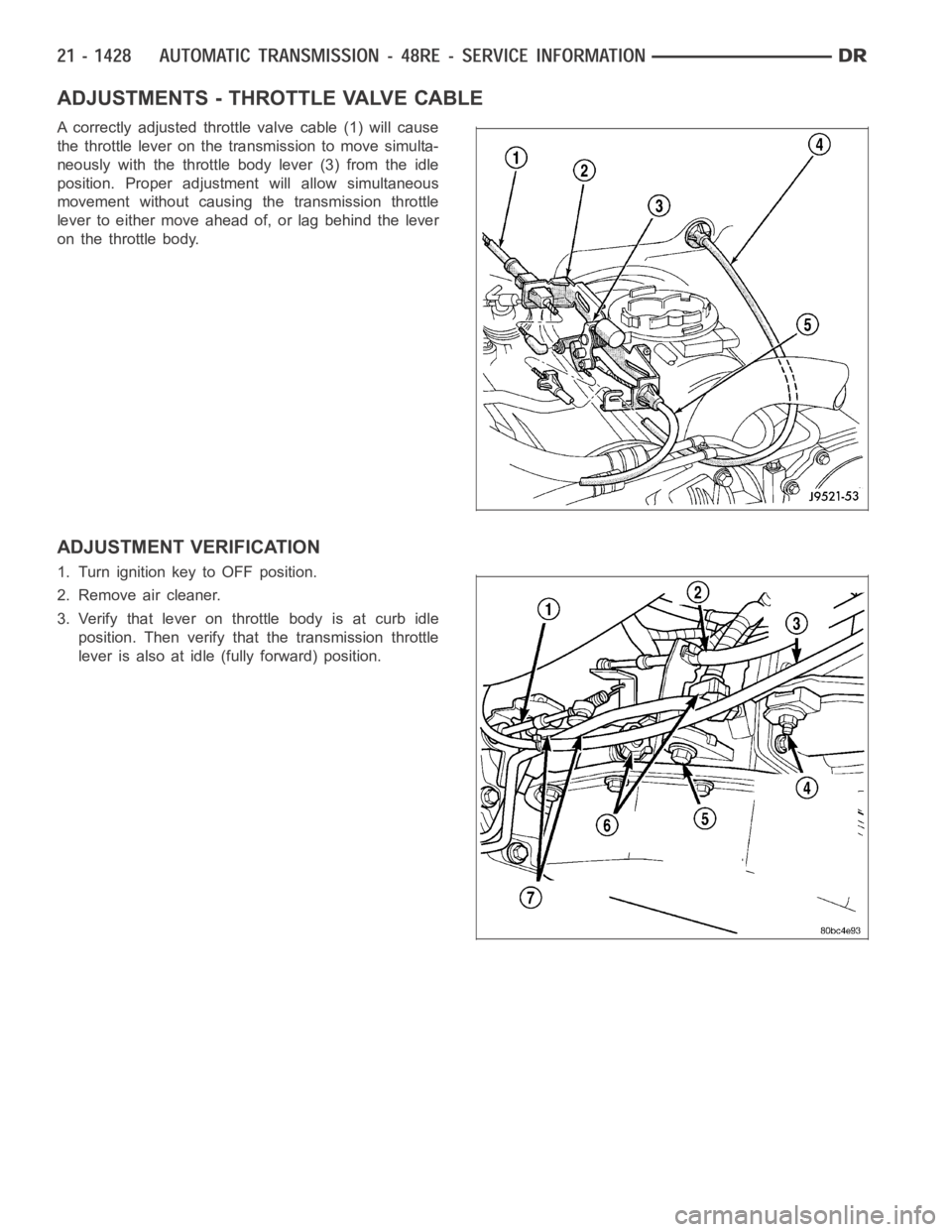
A correctly adjusted throttle valve cable (1) will cause
the throttle lever on the transmission to move simulta-
neously with the throttle body lever (3) from the idle
position. Proper adjustment will allow simultaneous
movement without causing the transmission throttle
lever to either move ahead of, or lag behind the lever
on the throttle body.
ADJUSTMENT VERIFICATION
1. Turn ignition key to OFF position.
2. Remove air cleaner.
3. Verify that lever on throttle body is at curb idle
position. Then verify that the transmission throttle
lever is also at idle (fully forward) position.
Page 3961 of 5267
SWITCH-TOW/HAUL OVERDRIVE
DESCRIPTION
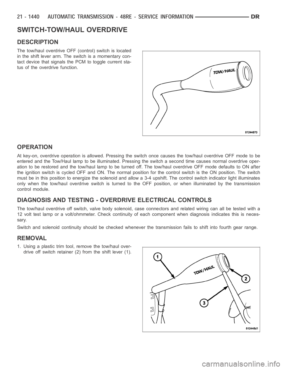
The tow/haul overdrive OFF (control) switch is located
in the shift lever arm. The switch is a momentary con-
tact device that signals the PCM to toggle current sta-
tus of the overdrive function.
OPERATION
At key-on, overdrive operation is allowed. Pressing the switch once causes the tow/haul overdrive OFF mode to be
entered and the Tow/Haul lamp to be illuminated. Pressing the switch a second time causes normal overdrive oper-
ationtoberestoredandthetow/haullamptobeturnedoff.Thetow/hauloverdrive OFF mode defaults to ON after
the ignition switch is cycled OFF and ON. The normal position for the control switch is the ON position. The switch
must be in this position to energize the solenoid and allow a 3-4 upshift. The control switch indicator light illuminates
only when the tow/haul overdrive switch is turned to the OFF position, or when illuminated by the transmission
control module.
DIAGNOSIS AND TESTING - OVERDRIVE ELECTRICAL CONTROLS
The tow/haul overdrive off switch, valve body solenoid, case connectors and related wiring can all be tested with a
12 volt test lamp or a volt/ohmmeter. Check continuity of each component when diagnosis indicates this is neces-
sary.
Switch and solenoid continuity shouldbe checked whenever the transmission fails to shift into fourth gear range.
REMOVAL
1. Using a plastic trim tool, remove the tow/haul over-
drive off switch retainer (2) from the shift lever (1).
Page 4341 of 5267
POSSIBLE CAUSE OF WIND NOISE
Moldings standing away from body surface can catch wind and whistle.
Gaps in sealed areas behind overhanging body flanges can cause wind-rushing sounds.
Misaligned movable components.
Missing or improperly installed plugs in pillars.
Weld burn through holes.
Improperly installed roof rack cross bars.
STANDARD PROCEDURE
BODY LUBRICATION
All mechanisms and linkages should be lubricated when necessary. This will maintain ease of operation and provide
protection against rust and excessive wear. The weatherstrip seals should be lubricated to prolong their life as well
as to improve door sealing.
All applicable exterior and interior vehicle operating mechanisms should be inspected and cleaned. Pivot/sliding con-
tact areas on the mechanisms should then be lubricated.
1. When necessary, lubricate the operating mechanisms with the specifiedlubricants.
2. Apply silicone lubricant to a clothand wipe it on door seals to avoid over-spray that can soil passenger’s cloth-
ing.
3. Before applying lubricant, the component should be wiped clean. After lubrication, any excess lubricant should be
removed.
4. The hood latch, latch release mechanism, latch striker, and safety latch should be lubricated periodically.
5. The door lock cylinders should be lubricated twice each year (preferably autumn and spring).
Spray a small amount of lock cylinder lubricant directly into the lock cylinder.
Apply a small amount to the key and insert it into the lock cylinder.
Rotate it to the locked position and then back to the unlocked position several times.
Remove the key. Wipe the lubricant from it with a clean cloth to avoid soiling of clothing.
HEAT STAKING
1. Remove trim panel.
2. Bend or move the trim panel components at the heat staked joints. Observethe heat staked locations and/or
component seams for looseness.
3. Heat stake the components.
a. If the heat staked or component seam location is loose, hold the two components tightly together and using
a soldering gun with a flat tip, melt the material securing the components together. Do not over heat the
affected area, damage to the exterior of the trim panel may occur.
b. Iftheheatstakedmaterialisbrokenormissing,useahotglueguntoapplynewmaterialtotheareatobe
repaired. The panels that are being heat staked must be held together whiletheapplyingtheglue.Oncethe
new material is in place, it may be necessary to use a soldering gun to melt the newly applied material. Do
not over heat the affected area, damage to the exterior of the trim panel mayoccur.
4. Allow the repaired area to cool and verify the repair.
5. Install trim panel.
BUZZ, SQUEAK & RATTLE
Buzz, Squeak & Rattles (BSR) may be caused by any one or more of the followingand may be corrected as indi-
cated:
Loose fasteners should be tightened to specifications.
Damaged or missing clips should be replaced.
Damaged trim panels should be replaced.
Incorrectly installed trim panels should be reinstalled properly.
Page 4609 of 5267
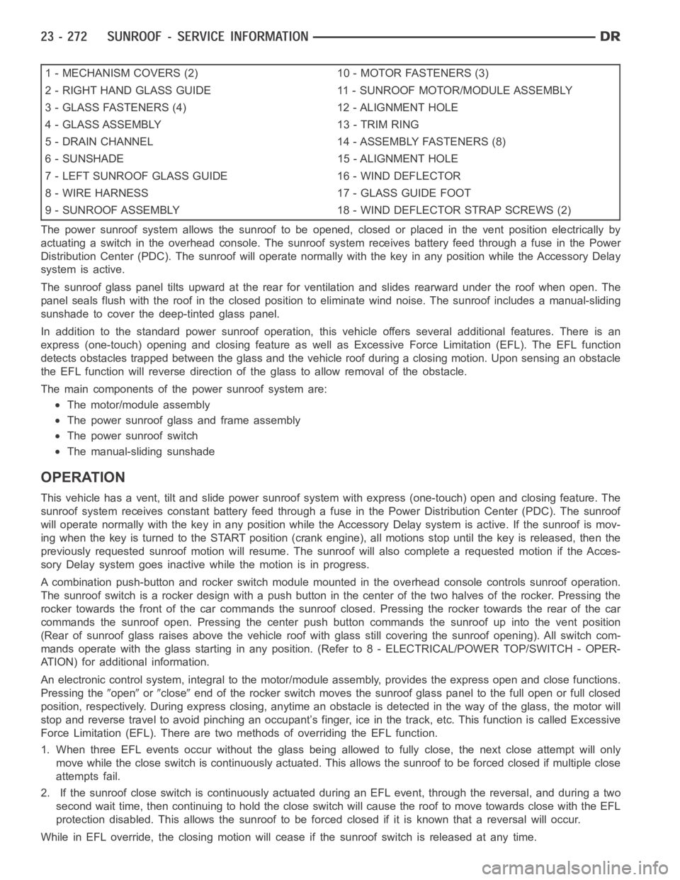
1 - MECHANISM COVERS (2) 10 - MOTOR FASTENERS (3)
2 - RIGHT HAND GLASS GUIDE 11 - SUNROOF MOTOR/MODULE ASSEMBLY
3 - GLASS FASTENERS (4) 12 - ALIGNMENT HOLE
4 - GLASS ASSEMBLY 13 - TRIM RING
5 - DRAIN CHANNEL 14 - ASSEMBLY FASTENERS (8)
6 - SUNSHADE 15 - ALIGNMENT HOLE
7 - LEFT SUNROOF GLASS GUIDE 16 - WIND DEFLECTOR
8 - WIRE HARNESS 17 - GLASS GUIDE FOOT
9 - SUNROOF ASSEMBLY 18 - WIND DEFLECTOR STRAP SCREWS (2)
The power sunroof system allows the sunroof to be opened, closed or placed in the vent position electrically by
actuating a switch in the overhead console. The sunroof system receives battery feed through a fuse in the Power
Distribution Center (PDC). The sunroof will operate normally with the keyin any position while the Accessory Delay
system is active.
The sunroof glass panel tilts upward at the rear for ventilation and slidesrearward under the roof when open. The
panel seals flush with the roof in the closed position to eliminate wind noise. The sunroof includes a manual-sliding
sunshade to cover the deep-tinted glass panel.
In addition to the standard power sunroof operation, this vehicle offers several additional features. There is an
express (one-touch) opening and closing feature as well as Excessive Force Limitation (EFL). The EFL function
detects obstacles trapped between the glass and the vehicle roof during a closing motion. Upon sensing an obstacle
the EFL function will reverse direction of the glass to allow removal of theobstacle.
The main components of thepower sunroof system are:
The motor/module assembly
The power sunroof glass and frame assembly
The power sunroof switch
The manual-sliding sunshade
OPERATION
This vehicle has a vent, tilt and slide power sunroof system with express (one-touch) open and closing feature. The
sunroof system receives constant battery feed through a fuse in the Power Distribution Center (PDC). The sunroof
will operate normally with the key in any position while the Accessory Delay system is active. If the sunroof is mov-
ing when the key is turned to the START position (crank engine), all motionsstop until the key is released, then the
previously requested sunroof motion will resume. The sunroof will also complete a requested motion if the Acces-
sory Delay system goes inactivewhile the motion is in progress.
A combination push-button and rocker switch module mounted in the overhead console controls sunroof operation.
The sunroof switch is a rocker design with a push button in the center of the two halves of the rocker. Pressing the
rocker towards the front of the car commands the sunroof closed. Pressing the rocker towards the rear of the car
commands the sunroof open. Pressing the center push button commands the sunroof up into the vent position
(Rear of sunroof glass raises above the vehicle roof with glass still covering the sunroof opening). All switch com-
mands operate with the glass startingin any position. (Refer to 8 - ELECTRICAL/POWER TOP/SWITCH - OPER-
ATION) for additional information.
An electronic control system, integralto the motor/module assembly, provides the express open and close functions.
Pressing the
openorcloseend of the rocker switch moves the sunroof glass panel to the full open or fullclosed
position, respectively. During express closing, anytime an obstacle is detected in the way of the glass, the motor will
stop and reverse travel to avoid pinching an occupant’s finger, ice in the track, etc. This function is called Excessive
Force Limitation (EFL). There are two methods of overriding the EFL function.
1. When three EFL events occur without the glass being allowed to fully close, the next close attempt will only
move while the close switch is continuously actuated. This allows the sunrooftobeforcedclosedifmultipleclose
attempts fail.
2. If the sunroof close switch is continuously actuated during an EFL event, through the reversal, and during a two
second wait time, then continuing to hold the close switch will cause the roof to move towards close with the EFL
protection disabled. This allows the sunroof to be forced closed if it is known that a reversal will occur.
While in EFL override, the closing motion will cease if the sunroof switch is released at any time.
Page 4699 of 5267
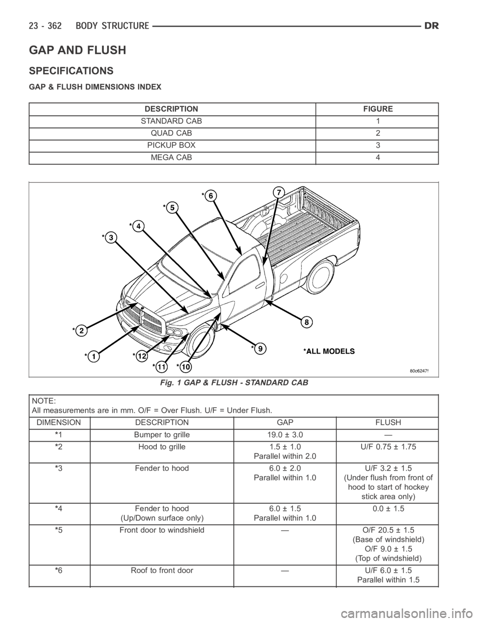
GAP AND FLUSH
SPECIFICATIONS
GAP & FLUSH DIMENSIONS INDEX
DESCRIPTION FIGURE
STANDARD CAB 1
QUAD CAB 2
PICKUP BOX 3
MEGA CAB 4
NOTE:
All measurements are in mm. O/F = Over Flush. U/F = Under Flush.
DIMENSION DESCRIPTION GAP FLUSH
*1 Bumper to grille 19.0 ± 3.0 —
*2 Hood to grille 1.5 ± 1.0
Parallel within 2.0U/F 0.75 ± 1.75
*3 Fender to hood 6.0 ± 2.0
Parallel within 1.0U/F 3.2 ± 1.5
(Under flush from front of
hood to start of hockey
stick area only)
*4 Fender to hood
(Up/Down surface only)6.0 ± 1.5
Parallel within 1.00.0 ± 1.5
*5 Front door to windshield — O/F 20.5 ± 1.5
(Base of windshield)
O/F 9.0 ± 1.5
(Top of windshield)
*6 Roof to front door — U/F 6.0 ± 1.5
Parallel within 1.5
Fig. 1 GAP & FLUSH - STANDARD CAB
Page 4703 of 5267
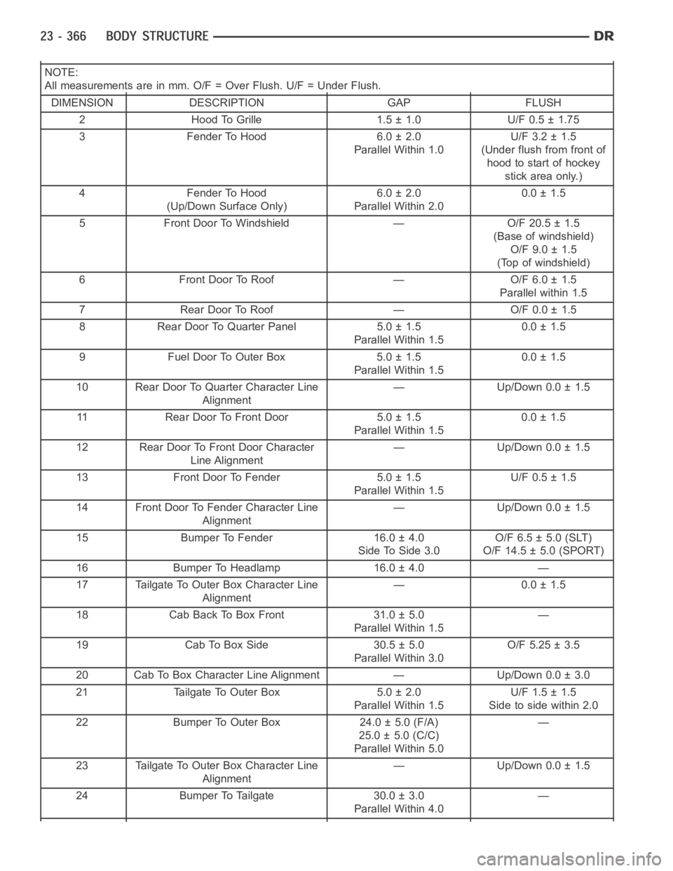
NOTE:
All measurements are in mm. O/F = Over Flush. U/F = Under Flush.
DIMENSION DESCRIPTION GAP FLUSH
2 Hood To Grille 1.5 ± 1.0 U/F 0.5 ± 1.75
3 Fender To Hood 6.0 ± 2.0
Parallel Within 1.0U/F 3.2 ± 1.5
(Under flush from front of
hood to start of hockey
stick area only.)
4 Fender To Hood
(Up/Down Surface Only)6.0 ± 2.0
Parallel Within 2.00.0 ± 1.5
5 Front Door To Windshield — O/F 20.5 ± 1.5
(Base of windshield)
O/F 9.0 ± 1.5
(Top of windshield)
6 Front Door To Roof — O/F 6.0 ± 1.5
Parallel within 1.5
7 Rear Door To Roof — O/F 0.0 ± 1.5
8 Rear Door To Quarter Panel 5.0 ± 1.5
Parallel Within 1.50.0 ± 1.5
9 Fuel Door To Outer Box 5.0 ± 1.5
Parallel Within 1.50.0 ± 1.5
10 Rear Door To Quarter Character Line
Alignment— Up/Down 0.0 ± 1.5
11 Rear Door To Front Door 5.0 ± 1.5
Parallel Within 1.50.0 ± 1.5
12 Rear Door To Front Door Character
Line Alignment— Up/Down 0.0 ± 1.5
13 Front Door To Fender 5.0 ± 1.5
Parallel Within 1.5U/F 0.5 ± 1.5
14 Front Door To Fender Character Line
Alignment— Up/Down 0.0 ± 1.5
15 Bumper To Fender 16.0 ± 4.0
Side To Side 3.0O/F 6.5 ± 5.0 (SLT)
O/F 14.5 ± 5.0 (SPORT)
16 Bumper To Headlamp 16.0 ± 4.0 —
17 Tailgate To Outer Box Character Line
Alignment— 0.0 ± 1.5
18 Cab Back To Box Front 31.0 ± 5.0
Parallel Within 1.5—
19 Cab To Box Side 30.5 ± 5.0
Parallel Within 3.0O/F 5.25 ± 3.5
20 Cab To Box Character Line Alignment — Up/Down 0.0 ± 3.0
21 Tailgate To Outer Box 5.0 ± 2.0
Parallel Within 1.5U/F 1.5 ± 1.5
Side to side within 2.0
22 Bumper To Outer Box 24.0 ± 5.0 (F/A)
25.0 ± 5.0 (C/C)
Parallel Within 5.0—
23 Tailgate To Outer Box Character Line
Alignment— Up/Down 0.0 ± 1.5
24 Bumper To Tailgate 30.0 ± 3.0
Parallel Within 4.0—
Page 5193 of 5267
EMISSIONS CONTROL
DESCRIPTION
STATE DISPLAY TEST MODE
The switch inputs to the Powertrain Control Module (PCM) have two recognized states; HIGH and LOW. For this
reason, the PCM cannot recognize the difference between a selected switchposition versus an open circuit, a short
circuit, or a defective switch. If the State Display screen shows the changefromHIGHtoLOWorLOWtoHIGH,
assume the entire switch circuit to the PCM functions properly. Connect the DRB scan tool to the data link con-
nector and access the state display screen. Then access either State Display Inputs and Outputs or State Display
Sensors.
CIRCUIT ACTUATION TEST MODE
The Circuit Actuation Test Mode checks for proper operation of output circuits or devices the Powertrain Control
Module (PCM) may not internally recognize. The PCM attempts to activate these outputs and allow an observer to
verify proper operation. Most of the tests provide an audible or visual indication of device operation (click of relay
contacts, fuel spray, etc.). Except for intermittent conditions, if a device functions properly during testing, assume the
device, its associated wiring, and driver circuit work correctly. Connect the DRB scan tool to the data link connector
and access the Actuators screen.
DIAGNOSTIC TROUBLE CODES
A Diagnostic Trouble Code (DTC) indicates the PCM has recognized an abnormal condition in the system.
Remember that DTC’s are the results of a system or circuit failure, but do not directly identify the failed
component or components.
BULB CHECK
Each time the ignition key is turned to the ON position, the malfunction indicator (check engine) lamp on the instru-
ment panel should illuminate for approximately 2 seconds then go out. Thisis done for a bulb check.
OBTAINING DTC’S USING DRB SCAN TOOL
1. Obtain the applicable Powertrain Diagnostic Manual.
2. Obtain the DRB Scan Tool.
3. Connect the DRB Scan Tool to the data link (diagnostic) connector. This connector is located in the passenger
compartment at the lower edge of instrument panel, and near the steering column.
4. Turn the ignition switch on and access the “Read Fault” screen.
5. Record all the DTC’s and “freeze frame” information shown on the DRB scantool.
6. To erase DTC’s, use the “Erase Trouble Code” data screen on the DRB scan tool.Do not erase any DTC’s
until problems have been investigated and repairs have been performed.
TA S K M A N A G E R
The PCM is responsible for efficiently coordinating the operation of all the emissions-related components. The PCM
is also responsible for determining if the diagnostic systems are operating properly. The software designed to carry
out these responsibilities is called the ’Task Manager’.
MONITORED SYSTEMS
There are new electronic circuit monitors that check fuel, emission, engine and ignition performance. These moni-
tors use information from various sensor circuits to indicate the overalloperation of the fuel, engine, ignition and
emission systems and thus the emissions performance of the vehicle.
The fuel, engine, ignition and emission systems monitors do not indicate aspecific component problem. They do
indicate that there is an implied problem within one of the systems and thata specific problem must be diagnosed.
If any of these monitors detect a problem affecting vehicle emissions, theMalfunction Indicator Lamp (MIL) will be
illuminated. These monitors generate Diagnostic Trouble Codes that can be displayed with the MIL or a scan tool.