Page 311 of 5267

Inspect the coolant system for proper level and condition.
Is the coolant level and condition OK?
Ye s>>
Go To 3
No>>
Inspect the vehicle for a coolant leak and add the necessary amount of coolant.
Perform the POWERTRAIN VERIFICATION TEST. (Refer to 9 - ENGINE - STANDARD PROCEDURE)
3.THERMOSTAT
NOTE: This test works best if performed on a cold engine (cold soak).
Ignition on, engine not running.
With a scan tool, read the Eng Coolant Tmp Deg value. If the engine was allowed to sit overnight (cold soak), the
temperature value should be a sensible value that is somewhere close to theambient temperature.
NOTE: If engine coolant temperature is above 82°C (180°F), allow the engine to cool until 65°C (150°F) is
reached.
Start the Engine.
During engine warm-up monitor the Eng Coolant Tmp Deg value. The temp deg value change should be a smooth
transition from start up to normal operating temp 82°C (180°F). Also monitor the actual coolant temperature with a
thermometer.
NOTE: As the engine warms up to operating temperature, the actual coolant temperature (thermometer read-
ing) and the Eng Coolant Tmp Deg on the scan tool should stay relatively closetoeachother.
Using the appropriate service information, determine the proper openingtemperature of the thermostat.
Did the thermostat open at the proper temperature?
Ye s>>
Go To 4
No>>
Replace the thermostat.
Perform the POWERTRAIN VERIFICATION TEST. (Refer to 9 - ENGINE - STANDARD PROCEDURE)
4.ECT SENSOR
Connect a jumper between the (K2) ECT Signal circuit and the (K900)
Sensor ground circuit in the ECT Sensor harness connector.
Turn the ignition off.
Disconnect the ECT Sensor harness connector.
With a scan tool, read the ECT voltage.
Is the voltage below 1.0 volt?
Ye s>>
Replace the ECT Sensor.
Perform the POWERTRAIN VERIFICATION TEST. (Refer to
9 - ENGINE - STANDARD PROCEDURE)
No>>
Go To 5
Page 314 of 5267

9.(K2) ECT SIGNAL CIRCUIT SHORTED TO THE (K900) SENSOR GROUND CIRCUIT
Measure the resistance between the (K2) ECT Signal circuit and the
(K900) Sensor ground circuit in the ECT Sensor harness connector.
Is the resistance below 5.0 ohms?
Ye s>>
Repair the short between the (K900) Sensor ground and the
(K2) ECT Signal circuit.
Perform the POWERTRAIN VERIFICATION TEST. (Refer to
9 - ENGINE - STANDARD PROCEDURE)
No>>
Go To 10
10.PCM
NOTE: Before continuing, check the PCM harness connector terminals for corrosion, damage, or terminal
push out. Repair as necessary.
Using the schematics as a guide, inspect the wire harness and connectors. Pay particular attention to all Power and
Ground circuits.
Were there any problems found?
Ye s>>
Repair as necessary.
Perform the POWERTRAIN VERIFICATION TEST. (Refer to 9 - ENGINE - STANDARD PROCEDURE)
No>>
Replace and program the Powertrain Control Module per Service Information.
Perform the POWERTRAIN VERIFICATION TEST. (Refer to 9 - ENGINE - STANDARD PROCEDURE)
Page 317 of 5267

3.APP SENSOR SWEEP
Ignition on, engine not running.
With a scan tool, monitor both APP Sensor voltage readings.
Slowly press the accelerator pedal from idle until it reaches the end stop near the floor.
APPS No.1 voltage should start at approximately 0.45 of a volt and increaseto approximately 4.6 volts with a
smooth transition.
APPS No.2 voltage should start at approximately 0.22 of a volt and increaseto approximately 2.31 volts with a
smooth transition.
Does the voltage for the appropriate sensor follow the list specification?
Ye s>>
Refer to the INTERMITTENT CONDITION Diagnostic Procedure.
Perform the POWERTRAIN VERIFICATION TEST. (Refer to 9 - ENGINE - STANDARD PROCEDURE)
No>>
Check the Signal and Return circuits for opens and shorts. If OK, Replace the APP Sensor Assembly
per Service Information. After installation is complete, with a scan toolselect the ETC RELEARN func-
tion to relearn the APPS values.
Perform the POWERTRAIN VERIFICATION TEST. (Refer to 9 - ENGINE - STANDARD PROCEDURE)
Page 321 of 5267
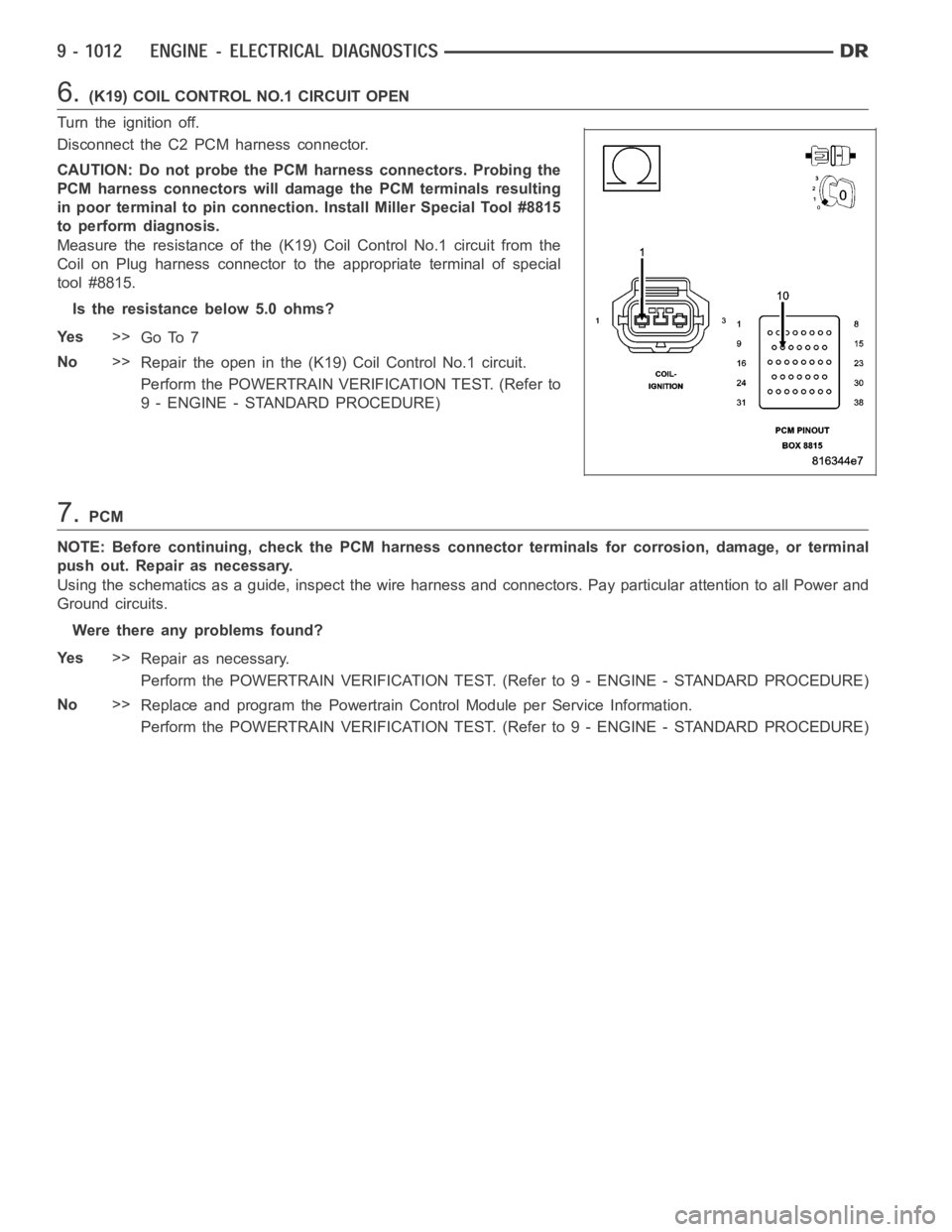
6.(K19) COIL CONTROL NO.1 CIRCUIT OPEN
Turn the ignition off.
Disconnect the C2 PCM harness connector.
CAUTION: Do not probe the PCM harness connectors. Probing the
PCM harness connectors will damage the PCM terminals resulting
in poor terminal to pin connection. Install Miller Special Tool #8815
to perform diagnosis.
Measure the resistance of the (K19) Coil Control No.1 circuit from the
Coil on Plug harness connector to the appropriate terminal of special
tool #8815.
Is the resistance below 5.0 ohms?
Ye s>>
Go To 7
No>>
Repair the open in the (K19) Coil Control No.1 circuit.
Perform the POWERTRAIN VERIFICATION TEST. (Refer to
9 - ENGINE - STANDARD PROCEDURE)
7.PCM
NOTE: Before continuing, check the PCM harness connector terminals for corrosion, damage, or terminal
push out. Repair as necessary.
Using the schematics as a guide, inspect the wire harness and connectors. Pay particular attention to all Power and
Ground circuits.
Were there any problems found?
Ye s>>
Repair as necessary.
Perform the POWERTRAIN VERIFICATION TEST. (Refer to 9 - ENGINE - STANDARD PROCEDURE)
No>>
Replace and program the Powertrain Control Module per Service Information.
Perform the POWERTRAIN VERIFICATION TEST. (Refer to 9 - ENGINE - STANDARD PROCEDURE)
Page 325 of 5267
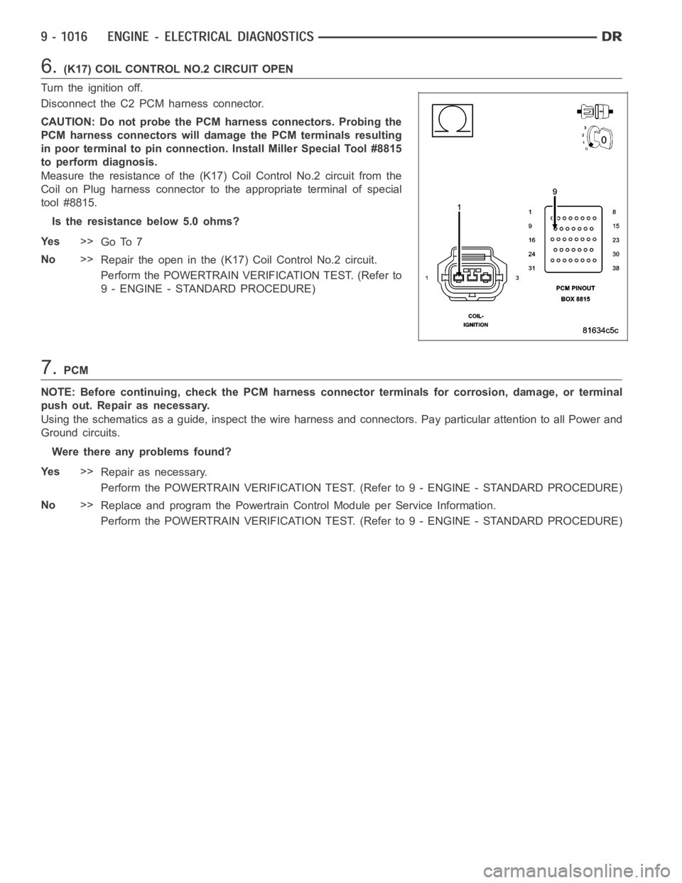
6.(K17) COIL CONTROL NO.2 CIRCUIT OPEN
Turn the ignition off.
Disconnect the C2 PCM harness connector.
CAUTION: Do not probe the PCM harness connectors. Probing the
PCM harness connectors will damage the PCM terminals resulting
in poor terminal to pin connection. Install Miller Special Tool #8815
to perform diagnosis.
Measure the resistance of the (K17) Coil Control No.2 circuit from the
Coil on Plug harness connector to the appropriate terminal of special
tool #8815.
Is the resistance below 5.0 ohms?
Ye s>>
Go To 7
No>>
Repair the open in the (K17) Coil Control No.2 circuit.
Perform the POWERTRAIN VERIFICATION TEST. (Refer to
9 - ENGINE - STANDARD PROCEDURE)
7.PCM
NOTE: Before continuing, check the PCM harness connector terminals for corrosion, damage, or terminal
push out. Repair as necessary.
Using the schematics as a guide, inspect the wire harness and connectors. Pay particular attention to all Power and
Ground circuits.
Were there any problems found?
Ye s>>
Repair as necessary.
Perform the POWERTRAIN VERIFICATION TEST. (Refer to 9 - ENGINE - STANDARD PROCEDURE)
No>>
Replace and program the Powertrain Control Module per Service Information.
Perform the POWERTRAIN VERIFICATION TEST. (Refer to 9 - ENGINE - STANDARD PROCEDURE)
Page 329 of 5267
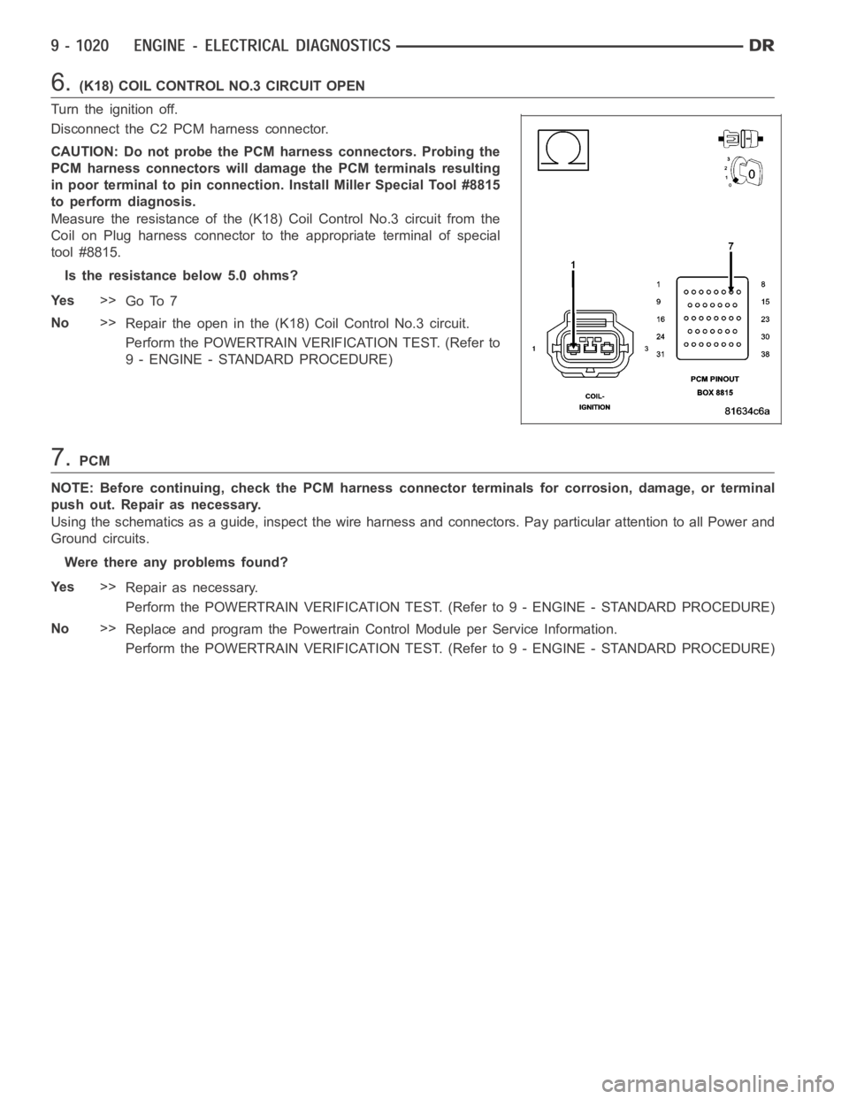
6.(K18) COIL CONTROL NO.3 CIRCUIT OPEN
Turn the ignition off.
Disconnect the C2 PCM harness connector.
CAUTION: Do not probe the PCM harness connectors. Probing the
PCM harness connectors will damage the PCM terminals resulting
in poor terminal to pin connection. Install Miller Special Tool #8815
to perform diagnosis.
Measure the resistance of the (K18) Coil Control No.3 circuit from the
Coil on Plug harness connector to the appropriate terminal of special
tool #8815.
Is the resistance below 5.0 ohms?
Ye s>>
Go To 7
No>>
Repair the open in the (K18) Coil Control No.3 circuit.
Perform the POWERTRAIN VERIFICATION TEST. (Refer to
9 - ENGINE - STANDARD PROCEDURE)
7.PCM
NOTE: Before continuing, check the PCM harness connector terminals for corrosion, damage, or terminal
push out. Repair as necessary.
Using the schematics as a guide, inspect the wire harness and connectors. Pay particular attention to all Power and
Ground circuits.
Were there any problems found?
Ye s>>
Repair as necessary.
Perform the POWERTRAIN VERIFICATION TEST. (Refer to 9 - ENGINE - STANDARD PROCEDURE)
No>>
Replace and program the Powertrain Control Module per Service Information.
Perform the POWERTRAIN VERIFICATION TEST. (Refer to 9 - ENGINE - STANDARD PROCEDURE)
Page 333 of 5267
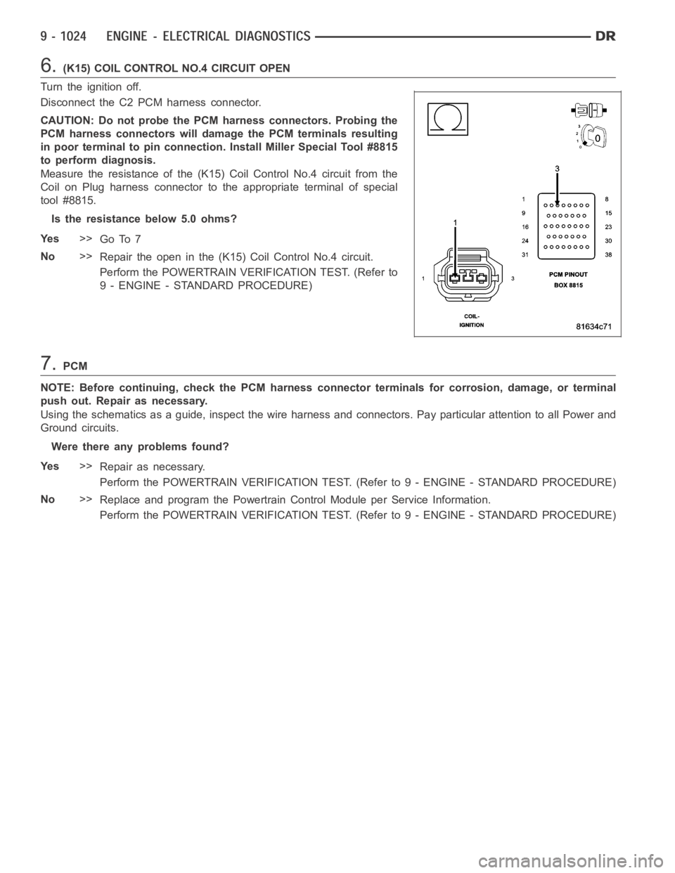
6.(K15) COIL CONTROL NO.4 CIRCUIT OPEN
Turn the ignition off.
Disconnect the C2 PCM harness connector.
CAUTION: Do not probe the PCM harness connectors. Probing the
PCM harness connectors will damage the PCM terminals resulting
in poor terminal to pin connection. Install Miller Special Tool #8815
to perform diagnosis.
Measure the resistance of the (K15) Coil Control No.4 circuit from the
Coil on Plug harness connector to the appropriate terminal of special
tool #8815.
Is the resistance below 5.0 ohms?
Ye s>>
Go To 7
No>>
Repair the open in the (K15) Coil Control No.4 circuit.
Perform the POWERTRAIN VERIFICATION TEST. (Refer to
9 - ENGINE - STANDARD PROCEDURE)
7.PCM
NOTE: Before continuing, check the PCM harness connector terminals for corrosion, damage, or terminal
push out. Repair as necessary.
Using the schematics as a guide, inspect the wire harness and connectors. Pay particular attention to all Power and
Ground circuits.
Were there any problems found?
Ye s>>
Repair as necessary.
Perform the POWERTRAIN VERIFICATION TEST. (Refer to 9 - ENGINE - STANDARD PROCEDURE)
No>>
Replace and program the Powertrain Control Module per Service Information.
Perform the POWERTRAIN VERIFICATION TEST. (Refer to 9 - ENGINE - STANDARD PROCEDURE)
Page 337 of 5267
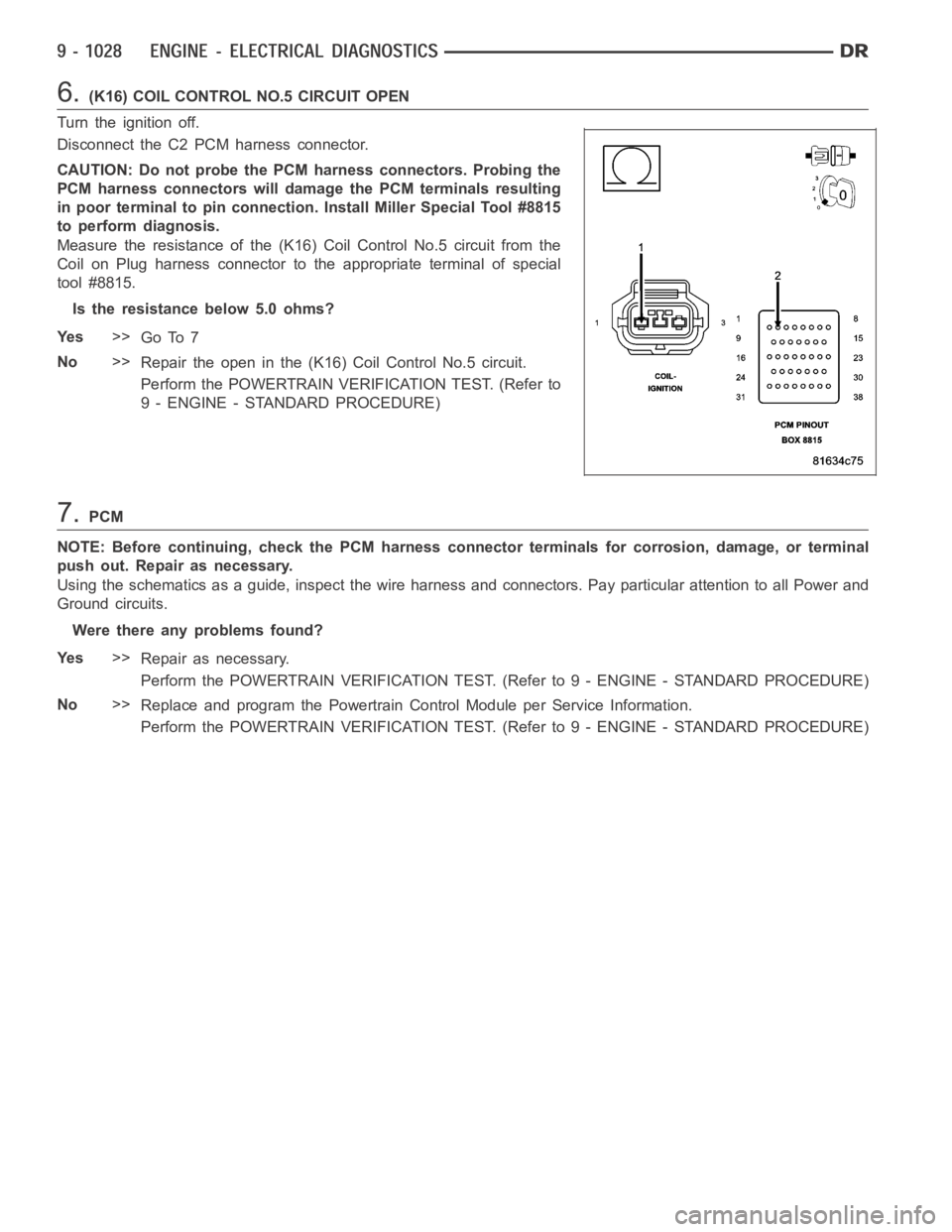
6.(K16) COIL CONTROL NO.5 CIRCUIT OPEN
Turn the ignition off.
Disconnect the C2 PCM harness connector.
CAUTION: Do not probe the PCM harness connectors. Probing the
PCM harness connectors will damage the PCM terminals resulting
in poor terminal to pin connection. Install Miller Special Tool #8815
to perform diagnosis.
Measure the resistance of the (K16) Coil Control No.5 circuit from the
Coil on Plug harness connector to the appropriate terminal of special
tool #8815.
Is the resistance below 5.0 ohms?
Ye s>>
Go To 7
No>>
Repair the open in the (K16) Coil Control No.5 circuit.
Perform the POWERTRAIN VERIFICATION TEST. (Refer to
9 - ENGINE - STANDARD PROCEDURE)
7.PCM
NOTE: Before continuing, check the PCM harness connector terminals for corrosion, damage, or terminal
push out. Repair as necessary.
Using the schematics as a guide, inspect the wire harness and connectors. Pay particular attention to all Power and
Ground circuits.
Were there any problems found?
Ye s>>
Repair as necessary.
Perform the POWERTRAIN VERIFICATION TEST. (Refer to 9 - ENGINE - STANDARD PROCEDURE)
No>>
Replace and program the Powertrain Control Module per Service Information.
Perform the POWERTRAIN VERIFICATION TEST. (Refer to 9 - ENGINE - STANDARD PROCEDURE)