2006 DODGE RAM SRT-10 sensor
[x] Cancel search: sensorPage 3285 of 5267
When Monitored:
Continuously with ignition on and engine running.
Set Condition:
This DTC will set if the monitored Line Pressure Sensor voltage is greater than or equal to 4.75 volts for the
period of 0.18 seconds
Possible Causes
(T38) LINE PRESSURE SENSOR SIGNAL CIRCUIT OPEN
(K900) SENSOR GROUND CIRCUIT OPEN
(T38) LINE PRESSURE SENSOR SIGNAL CIRCUIT SHORT TO VOLTAGE
LINE PRESSURE SENSOR
POWERTRAIN CONTROL MODULE
Always perform the 45RFE/545RFE Pre-Diagnostic Troubleshooting Procedure before proceeding. (Refer to
21 - TRANSMISSION/TRANSAXLE/AUTOMATIC - 45RFE/545RFE - STANDARD PROCEDURE)
Theory of Operation
Line pressure is electronically controlled by the Transmission Control System and is measured by the Line Pressure
Sensor (LPS). The desired line pressure is continuously being compared tothe actual line pressure and is regulated
by electronically changing the dutycycle of the Pressure Control Solenoid (PCS). (5% duty cycle = solenoid off =
max line pressure, 62% duty cycle =solenoid on = min line pressure).
The Transmission Control System calculates the desired line pressure based on inputs from the transmission and
engine. A calculated torque input to the transmission is used as the primary input of the desired line pressure cal-
culation and is called Torque Based Line Pressure. In addition, the line pressure is set to a preset level 827 to 931
kPa (120 to 135 psi) during shifts and in Park and Neutral to ensure consistent shift quality.
The monitored Line Pressure Sensor voltage should always be between 0.35 and 4.75 volts. Any monitored volt-
ages outside these parameters indicate an Line Pressure Sensor or wiring problem and will cause either DTC
P0934 or P0935 to set.
Diagnostic Test
1.CHECK TO SEE IF DTC IS CURRENT
With the scan tool, Check the STARTS SINCE SET counter for P0935.
NOTE: This counter only applies to the last DTC set.
Is the STARTS SINCE SET counter 2 or less?
Ye s>>
Go To 2
No>>
Go To 6
2.CHECK THE PCM AND WIRING
Turn the ignition off to the lock position.
Remove the Ignition Switch Feed fuse from the TIPM.
CAUTION: Removal of the Ignition Switch Feed fuse from the TIPM will prevent the vehicle from being
startedingear.
WARNING: The Ignition Switch Feed fuse must be removed from the TIPM. Failure to do so can result in
personal injury or death.
Install the Transmission Simulator, Miller tool #8333.
Ignition on, engine not running.
With the scan tool, monitor the Line Pressure.
Using the Transmission Simulator, set the rotary switch to each of the 3 line pressure positions.
Page 3286 of 5267
NOTE: The readings should be within ±14 kPa or 2.0 psi on the scan tool of the pressure reading specified
on Transmission Simulator.
Does the 3 line pressures on the scan tool match the Line pressure readings on the Transmission Sim-
ulator?
Ye s>>
Replace the Line Pressure Sensor per the Service Information.
Perform 45RFE/545RFE TRANSMISSION VERIFICATION TEST - VER 1. (Refer to 21- TRANSMIS-
SION/TRANSAXLE/AUTOMATIC - 45RFE/545RFE - STANDARD PROCEDURE)
No>>
Go To 3
3.CHECK THE (K900) SENSOR GROUND CIRCUIT FOR AN OPEN
Turn the ignition off to the lock position.
Disconnect the Transmission Simulator, Miller tool #8333.
Disconnect the PCM C2 harness connector and connect Miller tool
#8815.
CAUTION: Do not probe the PCM harness connectors. Probing the
PCM harness connectors will damage the PCM terminals resulting
in poor terminal to pin connection. Install Miller tool #8815 to per-
form diagnosis.
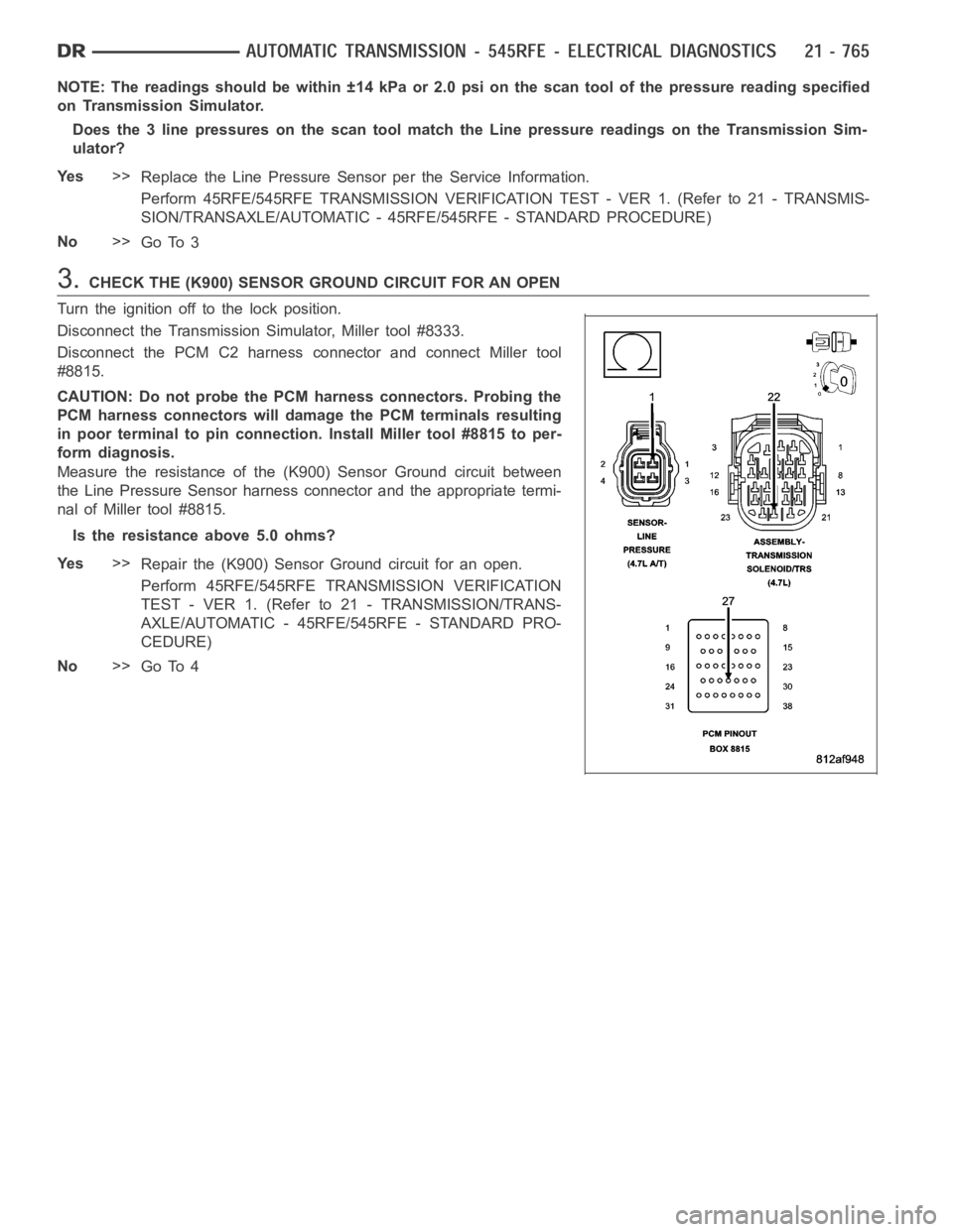
Measure the resistance of the (K900) Sensor Ground circuit between
the Line Pressure Sensor harness connector and the appropriate termi-
nal of Miller tool #8815.
Is the resistance above 5.0 ohms?
Ye s>>
Repair the (K900) Sensor Ground circuit for an open.
Perform 45RFE/545RFE TRANSMISSION VERIFICATION
TEST - VER 1. (Refer to 21 - TRANSMISSION/TRANS-
AXLE/AUTOMATIC - 45RFE/545RFE - STANDARD PRO-
CEDURE)
No>>
Go To 4
Page 3287 of 5267
4.CHECK THE (T38) LINE PRESSURE SENSOR SIGNAL CIRCUIT FOR AN OPEN
Disconnect the PCM C4 harness connector and connect Miller tool
#8815.
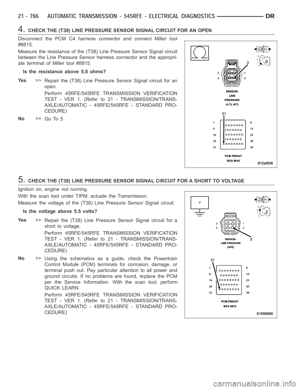
Measure the resistance of the (T38) Line Pressure Sensor Signal circuit
between the Line Pressure Sensor harness connector and the appropri-
ate terminal of Miller tool #8815.
Is the resistance above 5.0 ohms?
Ye s>>
Repair the (T38) Line Pressure Sensor Signal circuit for an
open.
Perform 45RFE/545RFE TRANSMISSION VERIFICATION
TEST - VER 1. (Refer to 21 - TRANSMISSION/TRANS-
AXLE/AUTOMATIC - 45RFE/545RFE - STANDARD PRO-
CEDURE)
No>>
Go To 5
5.CHECK THE (T38) LINE PRESSURE SENSOR SIGNAL CIRCUIT FOR A SHORT TO VOLTAGE
Ignition on, engine not running.
With the scan tool under TIPM, actuate the Transmission.
Measure the voltage of the (T38) Line Pressure Sensor Signal circuit.
Is the voltage above 5.5 volts?
Ye s>>
Repair the (T38) Line Pressure Sensor Signal circuit for a
short to voltage.
Perform 45RFE/545RFE TRANSMISSION VERIFICATION
TEST - VER 1. (Refer to 21 - TRANSMISSION/TRANS-
AXLE/AUTOMATIC - 45RFE/545RFE - STANDARD PRO-
CEDURE)
No>>
Using the schematics as a guide, check the Powertrain
Control Module (PCM) terminals for corrosion, damage, or
terminal push out. Pay particular attention to all power and
ground circuits. If no problems are found, replace the PCM
per the Service Information.With the scan tool, perform
QUICK LEARN.
Perform 45RFE/545RFE TRANSMISSION VERIFICATION
TEST - VER 1. (Refer to 21 - TRANSMISSION/TRANS-
AXLE/AUTOMATIC - 45RFE/545RFE - STANDARD PRO-
CEDURE)
Page 3292 of 5267
When Monitored:
In any forward gear with engine speed above 1000 RPM shortly after a shift and every minute thereafter.
Set Condition:
After a shift into a forward gear, with engine speed above 1000 RPM, the PCM momentarily turns on element
pressure to the Clutch circuits that don’t have pressure to identify the correct Pressure Switch closes. If the
Pressure Switch does not close 2 times, the DTC sets.
Possible Causes
LINE PRESSURE SENSOR
TRANSMISSION FLUID CONTAMINATION
RELATED DTC’S PRESENT
TRANSMISSION SOLENOID/TRS ASSEMBLY
EXCESSIVE DEBRIS IN OIL PAN
POOR LINE PRESSURE SENSOR CONNECTION
RELATED TCM POWER INPUT DTCS PRESENT
(T48) 4C PRESSURE SWITCH SENSE CIRCUIT OPEN
(F856) 5-VOLT SUPPLY CIRCUIT OPEN
(T48) 4C PRESSURE SWITCH SENSE CIRCUIT SHORT TO GROUND
(F856) 5-VOLT SUPPLY CIRCUIT SHORT TO GROUND
(T48) 4C PRESSURE SWITCH SENSE CIRCUIT SHORT TO OTHERS
TRANSMISSION SOLENOID/TRS ASSEMBLY
INTERNAL TRANSMISSION
POWERTRAIN CONTROL MODULE
Always perform the 45RFE/545RFE Pre-Diagnostic Troubleshooting Procedure before proceeding. (Refer to
21 - TRANSMISSION/TRANSAXLE/AUTOMATIC - 45RFE/545RFE - STANDARD PROCEDURE)
Theory of Operation
The Transmission Control System tests the pressure switches when they areoff. The test verifies that the switches
are operational (They will close with pressure applied). The Transmission Control System verifies that the switch
closes when the corresponding element is applied. If a switch fails to close, it is re-tested. If it fails the second test,
the DTC will set, the MIL will illuminate and the transmission system will default to the orderly Shutdown routine.
Diagnostic Test
1.DETERMINING IF RELATED DTC’S ARE PRESENT
With the scan tool, check for other transmission DTC’s
Is there any Loss of Prime, TCM Power Input, and/or Line Pressure Sensor DTCspresent?
Ye s>>
Refer to the Transmission category and perform the appropriate symptom. If the DTC P0944 is present,
perform its respective test first.
No>>
Go To 2
Page 3293 of 5267
2.CHECK FOR DTCS
With the scan tool, check Transmission DTCs.
Is the DTC P0770 also present?
Ye s>>
Refer to the symptom list and perform diagnostics for P0770.
No>>
Go To 3
3.OTHER DTCS PRESENT
With the scan tool, check for other transmission DTC’s
Are the DTCs P0988 and/or P1736 present also?
Ye s>>
Go To 12
No>>
Go To 4
4.CHECK TO SEE IF DTC IS CURRENT
With the scan tool, check if the DTC P0987-4C HYDRAULIC PRESSURE TEST FAILURE is active or stored.
Is the DTC P0987-4C HYDRAULIC PRESSURE TEST FAILURE active?
Ye s>>
Go To 5
No>>
Go To 17
5.CHECK IF THE LINE PRESSURE STAYS THE SAME
Start the engine.
Warm the transmission to 82° C or 180° F.
Firmly apply the brakes.
With the scan tool, monitor the Line Pressure during the following step.
Move the shift lever to each gear position, pausing momentarily in each position and record the line pressure read-
ing. Allow the pressure to stabilize for at least 5 seconds in each range.
Did the line pressure remain at a steady value between 585 and 655 kPa or 85 and 95 psi in each posi-
tion?
Ye s>>
Go To 6
No>>
Go To 10
6.CHECK THE LINE PRESSURE SENSOR CONNECTION
Ignition on,engine not running.
Withthescantool,monitortheLinePressure while firmly pushing the Transmission Line Pressure Sensor connector
inwards towards the Transmission.
Did the Line Pressure reading on the scan tool change to about 207 kPa or 30 psi when the connector
was pushed inward?
Ye s>>
Disconnect and properly reconnect the Line Pressure Sensor connector. Inspect terminals and repair as
necessary.
Perform 45RFE/545RFE TRANSMISSION VERIFICATION TEST - VER 1. (Refer to 21- TRANSMIS-
SION/TRANSAXLE/AUTOMATIC - 45RFE/545RFE - STANDARD PROCEDURE)
No>>
Go To 7
Page 3294 of 5267
7.CHECK THE LINE PRESSURE SENSOR OPERATION
Turn the ignition off to the lock position.
Remove the Ignition Switch Feed fuse from the TIPM.
CAUTION: Removal of the Ignition Switch Feed fuse from the TIPM will prevent the vehicle from being
startedingear.
WARNING: The Ignition Switch Feed fuse must be removed from the TIPM. Failure to do so can result in
personal injury or death.
Install the Transmission Simulator, Miller tool #8333.
With the Transmission Simulator select the
OFFposition on theInput/Output Speedswitch.
Ignition on, engine not running.
With the scan tool, monitor the Line Pressure while turning the Pressure Switch selector to each of the 3 line pres-
sure positions on the Transmission Simulator.
NOTE: All three scan tool Line Pressure readings should be steady and ±14 kPa or 2.0 psi of the reading
specified on the Transmission Simulator.
Did the scan tool Line Pressure readings match the specified readings on the Transmission Simulator
and remain steady in all three positions?
Ye s>>
Replace the Line Pressure Sensor per the Service Information.
Perform 45RFE/545RFE TRANSMISSION VERIFICATION TEST - VER 1. (Refer to 21- TRANSMIS-
SION/TRANSAXLE/AUTOMATIC - 45RFE/545RFE - STANDARD PROCEDURE)
No>>
Go To 8
8.CHECK THE (F856) 5-VOLT SUPPLY CIRCUIT FOR AN OPEN
Turn the ignition off to the lock position.
Disconnect Transmission Simulator.
Disconnect the PCM C1 harness connector and connect Miller tool
#8815.
CAUTION: Do not probe the PCM harness connectors. Probing the
PCM harness connectors will damage the PCM terminals resulting
in poor terminal to pin connection. Install Miller tool #8815 to per-
form diagnosis.
Measure the resistance of the (F856) 5-volt Supply circuit between the
Line Pressure Sensor harness connector and the appropriate terminal
of Miller tool #8815.
Is the resistance above 5.0 ohms?
Ye s>>
Repair the (F856) 5-volt Supply circuit for an open.
Perform 45RFE/545RFE TRANSMISSION VERIFICATION
TEST - VER 1. (Refer to 21 - TRANSMISSION/TRANS-
AXLE/AUTOMATIC - 45RFE/545RFE - STANDARD PRO-
CEDURE)
No>>
Go To 9
Page 3295 of 5267
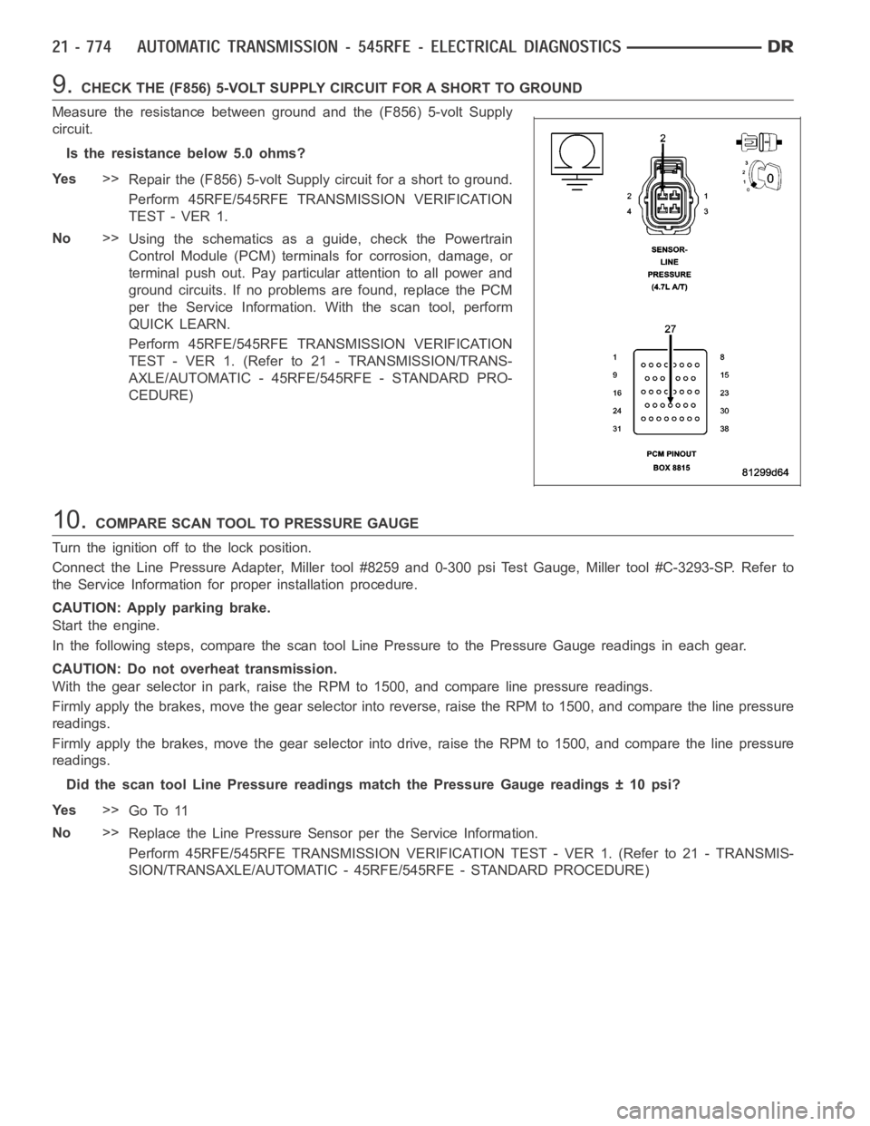
9.CHECK THE (F856) 5-VOLT SUPPLY CIRCUIT FOR A SHORT TO GROUND
Measure the resistance between ground and the (F856) 5-volt Supply
circuit.
Is the resistance below 5.0 ohms?
Ye s>>
Repair the (F856) 5-volt Supply circuit for a short to ground.
Perform 45RFE/545RFE TRANSMISSION VERIFICATION
TEST - VER 1.
No>>
Using the schematics as a guide, check the Powertrain
Control Module (PCM) terminals for corrosion, damage, or
terminal push out. Pay particular attention to all power and
ground circuits. If no problems are found, replace the PCM
per the Service Information.With the scan tool, perform
QUICK LEARN.
Perform 45RFE/545RFE TRANSMISSION VERIFICATION
TEST - VER 1. (Refer to 21 - TRANSMISSION/TRANS-
AXLE/AUTOMATIC - 45RFE/545RFE - STANDARD PRO-
CEDURE)
10.COMPARE SCAN TOOL TO PRESSURE GAUGE
Turn the ignition off to the lock position.
Connect the Line Pressure Adapter, Miller tool #8259 and 0-300 psi Test Gauge, Miller tool #C-3293-SP. Refer to
the Service Information for proper installation procedure.
CAUTION: Apply parking brake.
Start the engine.
In the following steps, compare thescan tool Line Pressure to the PressureGauge readings in each gear.
CAUTION: Do not overheat transmission.
With the gear selector in park, raise the RPM to 1500, and compare line pressure readings.
Firmly apply the brakes, move the gear selector into reverse, raise the RPMto 1500, and compare the line pressure
readings.
Firmly apply the brakes, move the gear selector into drive, raise the RPM to1500, and compare the line pressure
readings.
Did the scan tool Line Pressure readings match the Pressure Gauge readings±10psi?
Ye s>>
Go To 11
No>>
Replace the Line Pressure Sensor per the Service Information.
Perform 45RFE/545RFE TRANSMISSION VERIFICATION TEST - VER 1. (Refer to 21- TRANSMIS-
SION/TRANSAXLE/AUTOMATIC - 45RFE/545RFE - STANDARD PROCEDURE)
Page 3298 of 5267
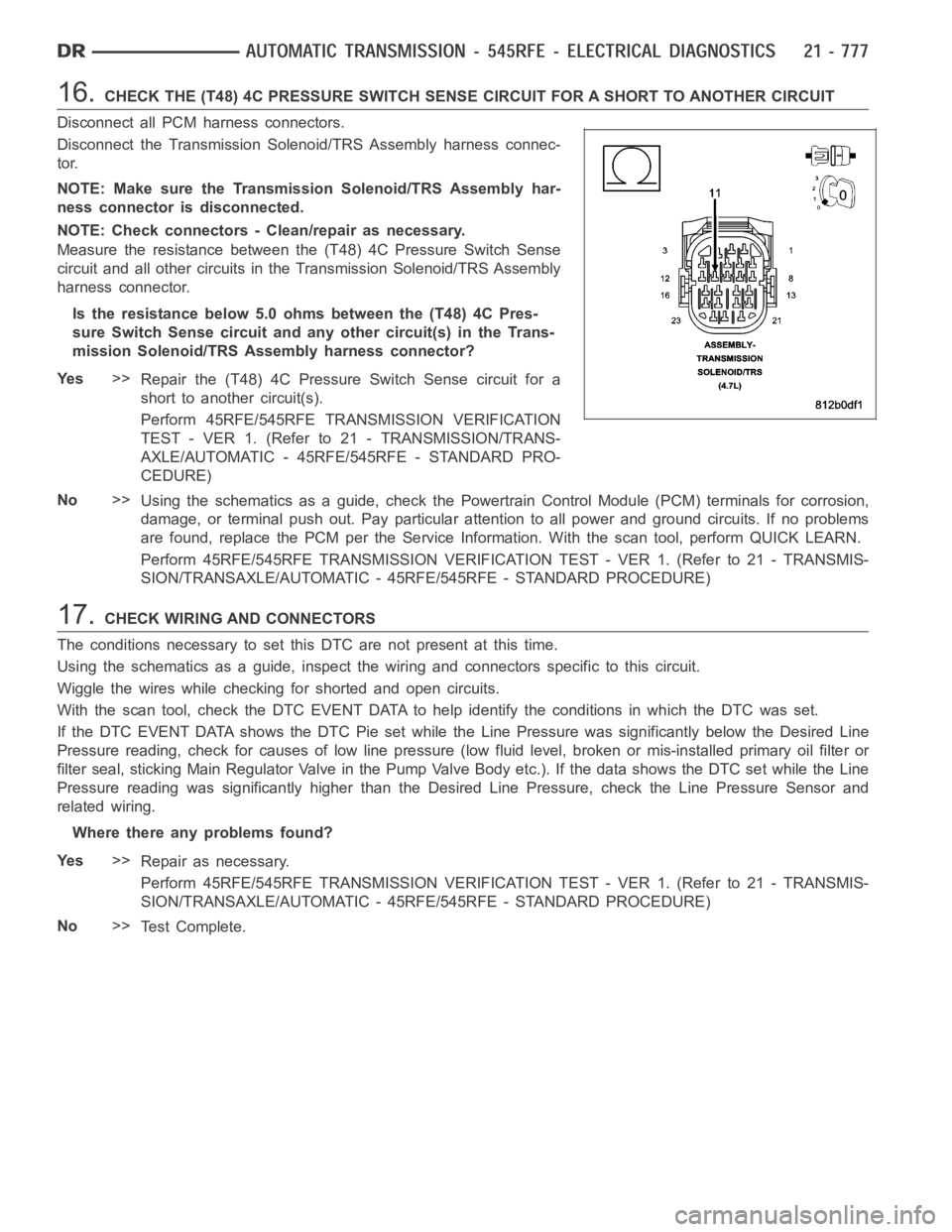
16.CHECK THE (T48) 4C PRESSURE SWITCH SENSE CIRCUIT FOR A SHORT TO ANOTHER CIRCUIT
Disconnect all PCM harness connectors.
Disconnect the Transmission Solenoid/TRS Assembly harness connec-
tor.
NOTE: Make sure the Transmission Solenoid/TRS Assembly har-
ness connector is disconnected.
NOTE: Check connectors - Clean/repair as necessary.
Measure the resistance between the (T48) 4C Pressure Switch Sense
circuit and all other circuits in the Transmission Solenoid/TRS Assembly
harness connector.
Is the resistance below 5.0 ohms between the (T48) 4C Pres-
sure Switch Sense circuit and any other circuit(s) in the Trans-
mission Solenoid/TRS Assembly harness connector?
Ye s>>
Repair the (T48) 4C Pressure Switch Sense circuit for a
short to another circuit(s).
Perform 45RFE/545RFE TRANSMISSION VERIFICATION
TEST - VER 1. (Refer to 21 - TRANSMISSION/TRANS-
AXLE/AUTOMATIC - 45RFE/545RFE - STANDARD PRO-
CEDURE)
No>>
Using the schematics as a guide, check the Powertrain Control Module (PCM)terminals for corrosion,
damage, or terminal push out. Pay particular attention to all power and ground circuits. If no problems
are found, replace the PCM per the Service Information. With the scan tool,perform QUICK LEARN.
Perform 45RFE/545RFE TRANSMISSION VERIFICATION TEST - VER 1. (Refer to 21- TRANSMIS-
SION/TRANSAXLE/AUTOMATIC - 45RFE/545RFE - STANDARD PROCEDURE)
17.CHECK WIRING AND CONNECTORS
The conditions necessary to set this DTC are not present at this time.
Using the schematics as a guide, inspect the wiring and connectors specifictothiscircuit.
Wiggle the wires while checking for shorted and open circuits.
With the scan tool, check the DTC EVENT DATA to help identify the conditionsin which the DTC was set.
If the DTC EVENT DATA shows the DTC Pie set while the Line Pressure was significantly below the Desired Line
Pressure reading, check for causes of low line pressure (low fluid level, broken or mis-installed primary oil filter or
filter seal, sticking Main Regulator Valve in the Pump Valve Body etc.). IfthedatashowstheDTCsetwhiletheLine
Pressure reading was significantly higher than the Desired Line Pressure, check the Line Pressure Sensor and
related wiring.
Where there any problems found?
Ye s>>
Repair as necessary.
Perform 45RFE/545RFE TRANSMISSION VERIFICATION TEST - VER 1. (Refer to 21- TRANSMIS-
SION/TRANSAXLE/AUTOMATIC - 45RFE/545RFE - STANDARD PROCEDURE)
No>>
Te s t C o m p l e t e .