2006 DODGE RAM SRT-10 sensor
[x] Cancel search: sensorPage 3307 of 5267
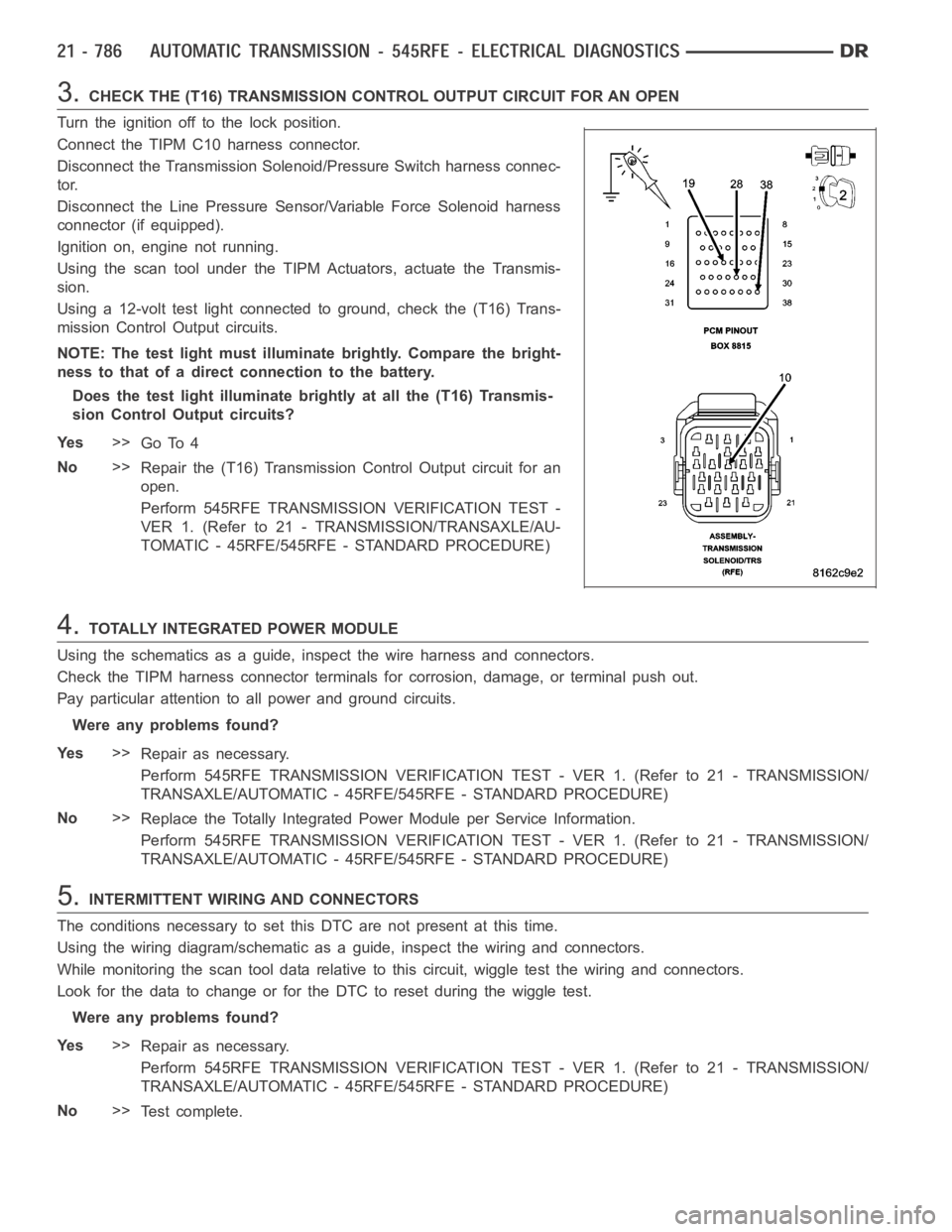
3.CHECK THE (T16) TRANSMISSION CONTROL OUTPUT CIRCUIT FOR AN OPEN
Turn the ignition off to the lock position.
Connect the TIPM C10 harness connector.
Disconnect the Transmission Solenoid/Pressure Switch harness connec-
tor.
Disconnect the Line Pressure Sensor/Variable Force Solenoid harness
connector (if equipped).
Ignition on, engine not running.
Using the scan tool under the TIPM Actuators, actuate the Transmis-
sion.
Using a 12-volt test light connected to ground, check the (T16) Trans-
mission Control Output circuits.
NOTE: The test light must illuminate brightly. Compare the bright-
ness to that of a direct connection to the battery.
Does the test light illuminate brightly at all the (T16) Transmis-
sion Control Output circuits?
Ye s>>
Go To 4
No>>
Repair the (T16) Transmission Control Output circuit for an
open.
Perform 545RFE TRANSMISSION VERIFICATION TEST -
VER 1. (Refer to 21 - TRANSMISSION/TRANSAXLE/AU-
TOMATIC - 45RFE/545RFE - STANDARD PROCEDURE)
4.TOTALLY INTEGRATED POWER MODULE
Using the schematics as a guide, inspect the wire harness and connectors.
Check the TIPM harness connector terminals for corrosion, damage, or terminal push out.
Pay particular attention to all power and ground circuits.
Were any problems found?
Ye s>>
Repair as necessary.
Perform 545RFE TRANSMISSION VERIFICATION TEST - VER 1. (Refer to 21 - TRANSMISSION/
TRANSAXLE/AUTOMATIC - 45RFE/545RFE - STANDARD PROCEDURE)
No>>
Replace the Totally Integrated Power Module per Service Information.
Perform 545RFE TRANSMISSION VERIFICATION TEST - VER 1. (Refer to 21 - TRANSMISSION/
TRANSAXLE/AUTOMATIC - 45RFE/545RFE - STANDARD PROCEDURE)
5.INTERMITTENT WIRING AND CONNECTORS
The conditions necessary to set this DTC are not present at this time.
Using the wiring diagram/schematic as a guide, inspect the wiring and connectors.
While monitoring the scan tool data relative to this circuit, wiggle test the wiring and connectors.
Look for the data to change or for the DTC to reset during the wiggle test.
Were any problems found?
Ye s>>
Repair as necessary.
Perform 545RFE TRANSMISSION VERIFICATION TEST - VER 1. (Refer to 21 - TRANSMISSION/
TRANSAXLE/AUTOMATIC - 45RFE/545RFE - STANDARD PROCEDURE)
No>>
Te s t c o m p l e t e .
Page 3312 of 5267
When Monitored:
With the ignition on. Battery voltage greater than 10 volts.
Set Condition:
An open condition of the Transmission Control Output circuit is detected by the Totally Integrated Power Mod-
ule (TIPM).
Possible Causes
(T16) TRANSMISSION CONTROL OUTPUT CIRCUIT OPEN
TOTALLY INTEGRATED POWER MODULE (TIPM)
Diagnostic Test
1.CHECK IF THE DTC IS ACTIVE
Ignition on, engine not running.
With the scan tool, select View DTCs.
Is the status Active for this DTC?
Ye s>>
Go to 2
No>>
Go to 4
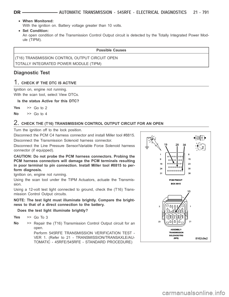
2.CHECK THE (T16) TRANSMISSION CONTROL OUTPUT CIRCUIT FOR AN OPEN
Turn the ignition off to the lock position.
Disconnect the PCM C4 harness connector and install Miller tool #8815.
Disconnect the Transmission Solenoid harness connector.
Disconnect the Line Pressure Sensor/Variable Force Solenoid harness
connector (if equipped).
CAUTION: Do not probe the PCM harness connectors. Probing the
PCM harness connectors will damage the PCM terminals resulting
in poor terminal to pin connection. Install Miller tool #8815 to per-
form diagnosis.
Ignition on, engine not running.
Using the scan tool under the TIPM Actuators, actuate the Transmis-
sion.
Using a 12-volt test light connected to ground, check the (T16) Trans-
mission Control Output circuits.
NOTE: The test light must illuminate brightly. Compare the bright-
ness to that of a direct connection to the battery.
Does the test light illuminate brightly?
Ye s>>
Go To 3
No>>
Repair the (T16) Transmission Control Output circuit for an
open.
Perform 545RFE TRANSMISSION VERIFICATION TEST -
VER 1. (Refer to 21 - TRANSMISSION/TRANSAXLE/AU-
TOMATIC - 45RFE/545RFE - STANDARD PROCEDURE)
Page 3315 of 5267
When Monitored:
With the ignition on. Battery voltage greater than 10 volts.
Set Condition:
An overcurrent condition is detected in the TCM Power Control circuit. OneTrip Fault. Three good trips to turn
off the MIL.
Possible Causes
LINE PRESSURE SENSOR VARIABLE FORCE SOLENOID
SOLENOID/PRESSURE SWITCH ASSEMBLY
POWERTRAIN CONTROL MODULE (PCM)
TOTALLY INTEGRATED POWER MODULE (TIPM)
Diagnostic Test
1.CHECK IF THE DTC IS ACTIVE
Ignition on, engine not running.
With a scan tool, read TIPM DTCs.
Is the DTC active at this time?
Ye s>>
Go To 2
No>>
Go To 5
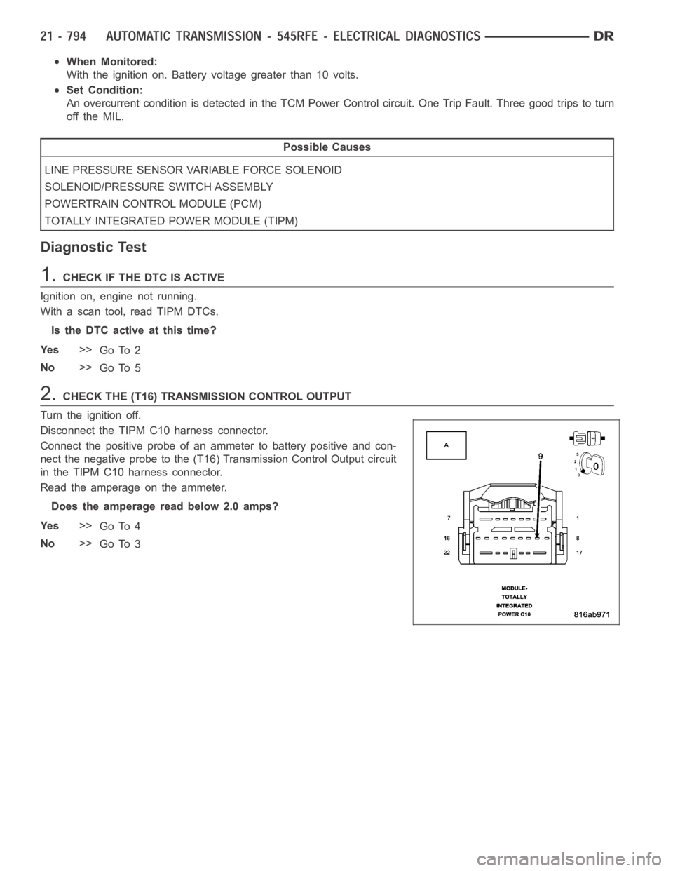
2.CHECK THE (T16) TRANSMISSION CONTROL OUTPUT
Turn the ignition off.
Disconnect the TIPM C10 harness connector.
Connect the positive probe of an ammeter to battery positive and con-
nect the negative probe to the (T16) Transmission Control Output circuit
in the TIPM C10 harness connector.
Read the amperage on the ammeter.
Does the amperage read below 2.0 amps?
Ye s>>
Go To 4
No>>
Go To 3
Page 3321 of 5267

P1736-GEAR RATIO ERROR IN 2ND PRIME
For a complete wiring diagramRefer to Section 8W.
When Monitored:
Continuously with the ignition on, engine running, with the transmissionin gear.
Set Condition:
If the ratio of the Input RPM to the Output RPM does not match the current gearratio. This DTC can take up
to five minutes of problem identification before illuminating the MIL
Possible Causes
RELATED DTC’S PRESENT
INPUT SPEED SENSOR OR WIRING
LOW FLUID LEVEL
CRACKED OR MIS-INSTALLED PRIMARY OIL FILTER OR SEAL
WORN SOLENOID SWITCH VALVE OR PLUGS
STUCK OR STICKING MAIN REGULATOR VALVE
BURNED UD OR 4C CLUTCH
CUT 4C OR UD PISTON SEAL
BROKEN 4C PISTON CASTING
BROKEN OR MISSING 4C BLEED ORIFICE
BROKEN OR MISSING UD BLEED ORIFICE
CUT 4C OR UD ACCUMULATOR PISTON SEAL
CRACKED 4C OR UD ACCUMULATOR PISTON
EXTRA CHECK BALL IN PASSAGE DOWNSTREAM OF #7 CHECK BALL POCKET
TRANSMISSION SOLENOID/TRS ASSEMBLY
BROKEN WELD - REACTION CARRIER TO REVERSE SUN GEAR
MISSING TEETH ON INPUT CLUTCH HUB TONE WHEEL
Always perform the 45RFE/545RFE Pre-Diagnostic Troubleshooting Procedure before proceeding. (Refer to
21 - TRANSMISSION/TRANSAXLE/AUTOMATIC - 45RFE/545RFE - STANDARD PROCEDURE)
Theory of Operation
The transmission system uses two speed sensors, one to measure input RPM and one to measure output RPM.
These inputs are essential for proper transmission operation. Therefore, the integrity of this data is verified through
the following checks:
1) When in gear, if the gear ratio does not compare to a known gear ratio, the corresponding in-gear trouble code
is set (DTCs P0731-36).
2) An excessive change in input or output speeds indicating signal intermittent which may result in the DTCs P0715
and/or P0720 to set.
3) If the common speed sensor ground circuit is lost, both sensor inputs will read the signal from the input speed
sensor at idle in neutral. Since the input speed sensor reads 60 teeth from the input clutch hub and the output
speed sensor reads 30 teeth from the park gear, the result is an apparent speed ratio of 1:2 and may cause the
DTC P1794 to set when at a stop.
Page 3322 of 5267

Diagnostic Test
1.DETERMINING IF RELATED DTC’S ARE PRESENT
With the scan tool, check for other transmission DTCs.
Are any Transmission: solenoid, line pressure, speed sensor, or loss of primeDTCspresent?
Ye s>>
Refer to appropriate symptom in the Transmission category. Perform the test for P0944-LOSS OF
PRIME first if it is present.
No>>
Go To 2
2.CHECK DTC EVENT DATA
With the scan tool, read and record the DTC EVENT DATA.
NOTE: Make sure to record all DTC EVENT DATA stored in the scan tool for future reference in this test
procedure.
Does the DTC EVENT DATA display information for the DTC P1736?
Ye s>>
Go To 3
No>>
Go To 6
3.CHECK RPM IN DTC EVENT DATA
Refer to the DTC EVENT DATA recorded earlier.
Does the Input RPM read zero?
Ye s>>
Check the input speed sensor and wiring. Refer to test P0715 and diagnose asif the DTC is current.
No>>
Go To 4
4.CHECK LINE PRESSURE READING
Refer to the DTC EVENT DATA recorded earlier.
Isthelinepressurereadingmorethan10 psi below the desired line pressure?
Ye s>>
Go To 5
No>>
Go To 6
5.PLUGGED TRANSMISSION OIL FILTER
Turn the ignition off to the lock position.
Remove and inspect the Transmission Oil Pan for excessive debris per the Service Information.
Remove and inspect the Primary Oil Filter per the Service Information.
NOTE: Make sure the Primary Transmission Oil Filter and/or seal is not cracked or split.
Does the Oil Pan contain excessive debris and/or is the Primary Oil Filter cracked or plugged?
Ye s>>
Repair the plugged, cracked, or split Primary Transmission Oil Filter and/or seal. If the Primary Trans-
mission Oil Filter is plugged, refer to the Service Information for the proper hydraulic clutch repair pro-
cedure.
Perform 45RFE/545RFE TRANSMISSION VERIFICATION TEST - VER 1. (Refer to 21- TRANSMIS-
SION/TRANSAXLE/AUTOMATIC - 45RFE/545RFE - STANDARD PROCEDURE)
No>>
Remove the Transmission Oil Pump per the Service Information. Check the main Regulator Valve for
sticking in its bore, scoring, and/or damage and clean and repair as necessary. If no problem is found,
replace the Transmission Solenoid/TRS Assembly.
Perform 45RFE/545RFE TRANSMISSION VERIFICATION TEST - VER 1. (Refer to 21- TRANSMIS-
SION/TRANSAXLE/AUTOMATIC - 45RFE/545RFE - STANDARD PROCEDURE)
Page 3323 of 5267
6.CHECK TO SEE IF DTC P1736 IS CURRENT
With the scan tool, perform the 2nd Prime Gear Clutch Test. Follow the instructions on the scan tool.
Increase the throttle angle, TPS Degree, to 30° for no more than a few seconds.
CAUTION: Do not overheat the transmission.
NOTE: If the 4C clutch is faulty, the overrunning clutch will hold and the slip test will pass. The 2nd Prime
Gear Clutch Test will not detect a faulty 4C clutch. However, it will detectafaultyUDclutch.
Did the clutch test pass, did the Input Speed remain at zero?
Ye s>>
Go To 7
No>>
Go To 9
7.CHECK FOR INTERMITTENT OPERATION
Check the Shifter adjustment per the Service Information.
Intermittent gear ratio DTCs can be set by problems in the Input and Output Speed Sensor circuits and/or Speed
Sensor Ground circuit.
Check the Speed Sensor wiring and connectors for good connection, then performawiggletestusingtheTrans-
mission Simulator, Miller tool #8333.
Were there any problems found?
Ye s>>
Repair as necessary.
Perform 45RFE/545RFE TRANSMISSION VERIFICATION TEST - VER 1. (Refer to 21- TRANSMIS-
SION/TRANSAXLE/AUTOMATIC - 45RFE/545RFE - STANDARD PROCEDURE)
No>>
Go To 8
8.CHECK FOR SLIPPAGE
With the scan tool, erase Transmission DTCs.
Road test the vehicle.
During the road test, operate in 4th gear, and perform kickdown shifts from4th to 2nd (prime) gears.
Is there an obvious slippage noticed in 4th or 2nd prime gears, or runaway onthe 4-2 shift?
Ye s>>
Go To 11
No>>
Go To 14
9.UD CLUTCH HYDRAULIC CIRCUIT
Remove Transmission Oil Pan and check for excessive debris.
Remove the Valve Body and air check the UD clutch hydraulic circuit (in the case) per the Service Information.
NOTE: The UD clutch passage contains a small bleed orifice, a small amount of air leakage is normal.
Were there any problems found, excessive debris and/or excessive air leakage in the UD clutch hydrau-
lic circuit?
Ye s>>
Repair as necessary. Check the UD clutch piston seals and the dribbler assembly, reaction shaft sup-
port seal rings, and the flatness of the pump valve body and pump housing faces. Check main regulator
valve for sticking in the bore.
Perform 45RFE/545RFE TRANSMISSION VERIFICATION TEST - VER 1. (Refer to 21- TRANSMIS-
SION/TRANSAXLE/AUTOMATIC - 45RFE/545RFE - STANDARD PROCEDURE)
No>>
Go To 10
Page 3335 of 5267

P1794-SPEED SENSOR GROUND ERROR
For a complete wiring diagramRefer to Section 8W
Page 3336 of 5267
When Monitored:
The gear ratio is monitored continuously while the Transmission is in gear.
Set Condition:
After a controller reset in neutral and a ratio of input to output, of 1 to 2. ThisDTCcantakeuptofiveminutes
of problem identification before illuminating the MIL.
Possible Causes
(T13) SPEED SENSOR GROUND CIRCUIT OPEN
(T13) SPEED SENSOR GROUND CIRCUIT SHORT TO GROUND
(T13) SPEED SENSOR GROUND CIRCUIT SHORT TO VOLTAGE
POWERTRAIN CONTROL MODULE
Always perform the 45RFE/545RFE Pre-Diagnostic Troubleshooting Procedure before proceeding. (Refer to
21 - TRANSMISSION/TRANSAXLE/AUTOMATIC - 45RFE/545RFE - STANDARD PROCEDURE)
Theory of Operation
The transmission system uses two speed sensors, one to measure input RPM and one to measure output RPM.
These inputs are essential for proper transmission operation. Therefore, the integrity of this data is verified through
the following checks:
1) When in gear, if the gear ratio does not compare to a known gear ratio, the corresponding in-gear trouble code
is set (DTCs P0731–36).
2) An excessive change in input or output speeds indicating signal intermittent which may result in the DTCs P0715
and/or P0720 to set.
3) If the common speed sensor ground circuit is lost, both sensor inputs will read the signal from the input speed
sensor at idle in neutral. Since the input speed sensor reads 60 teeth from the input clutch hub and the output
speed sensor reads 30 teeth from the park gear, the result is an apparent speed ratio of 1:2 and may cause the
DTC P1794 to set when at a stop.
Diagnostic Test
1.CHECK TO SEE IF DTC P1794 IS CURRENT
Engine Running, Shift lever in park.
With the scan tool, read the Transmission Output and Input Speed Sensor states.
Is the Output Speed Sensor reading twice the Input Speed Sensor reading?
Ye s>>
Go To 2
No>>
Go To 6
2.PCM AND WIRING
Turn the ignition off to the lock position.
Remove the Ignition Switch Feed fuse from the TIPM.
CAUTION: Removal of the Ignition Switch Feed fuse from the TIPM will prevent the vehicle from being
startedingear.
WARNING: The Ignition Switch Feed fuse must be removed from the TIPM. Failure to do so can result in
personal injury or death.
Install the Transmission Simulator, Miller tool 8333.
With the Transmission Simulator, set the Input/Output Speed selector switch to the
3000/1000position. Turn the
Input/Output Speed switch to
ON.
Ignition on, engine not running.