Page 3490 of 5267

SENSOR-TRANSMISSION RANGE
DESCRIPTION
The Transmission Range Sensor (TRS) is part of the solenoid module, which is mounted to the top of the valve
body inside the transmission.
The Transmission Range Sensor (TRS) has five switch contact pins that:
Determine shift lever position
Supply ground to the Starter Relay in Park and Neutral only.
Supply +12 V to the backup lamps in Reverse only.
The TRS also has an integrated temperature sensor (thermistor) that communicates transmission temperature to the
TCM and PCM.
OPERATION
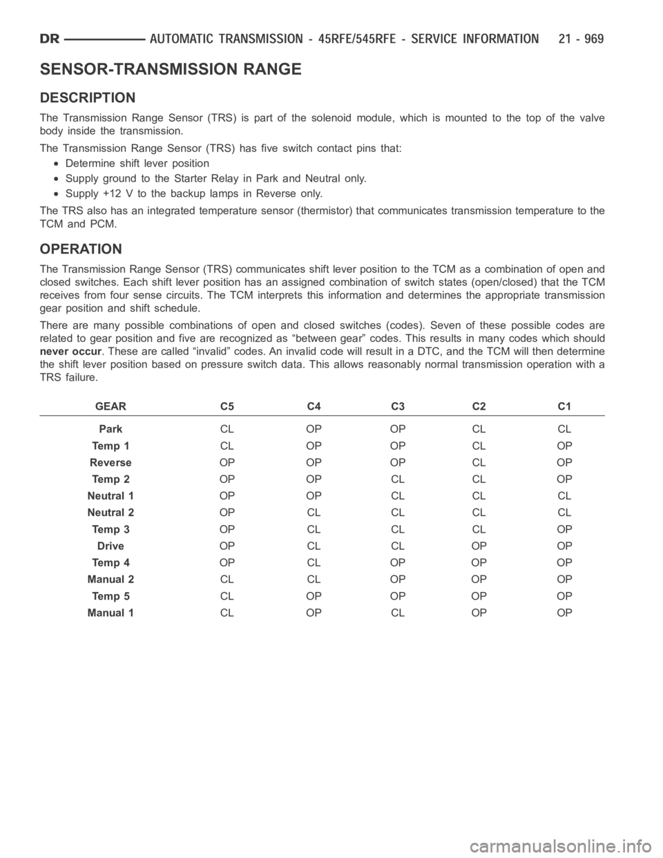
The Transmission Range Sensor (TRS) communicates shift lever position tothe TCM as a combination of open and
closed switches. Each shift lever position has an assigned combination ofswitch states (open/closed) that the TCM
receives from four sense circuits. The TCM interprets this information and determines the appropriate transmission
gear position and shift schedule.
There are many possible combinations of open and closed switches (codes).Seven of these possible codes are
related to gear position and five are recognized as “between gear” codes. This results in many codes which should
never occur. These are called “invalid” codes. An invalid code will result in a DTC, andthe TCM will then determine
the shift lever position based on pressure switch data. This allows reasonably normal transmission operation with a
TRS failure.
GEAR C5 C4 C3 C2 C1
ParkCL OP OP CL CL
Te m p 1CL OP OP CL OP
ReverseOP OP OP CL OP
Te m p 2OP OP CL CL OP
Neutral 1OP OP CL CL CL
Neutral 2OP CL CL CL CL
Te m p 3OP CL CL CL OP
DriveOP CL CL OP OP
Te m p 4OP CL OP OP OP
Manual 2CL CL OP OP OP
Te m p 5CL OP OP OP OP
Manual 1CL OP CL OP OP
Page 3494 of 5267
SENSOR-TRANSMISSION TEMPERATURE
DESCRIPTION
The transmission temperature sensor is a thermistor that is integral to the Transmission Range Sensor (TRS).
OPERATION
The transmission temperature sensor is used by the TCM to sense the temperature of the fluid in the sump. Since
fluid temperature can affect transmission shift quality and convertor lock up, the TCM requires this information to
determine which shift schedule to operate in.
Calculated Temperature
A failure in the temperature sensor or circuit will result in calculated temperature being substituted for actual tem-
perature. Calculated temperature is a predicted fluid temperature whichis calculated from a combination of inputs:
Battery (ambient) temperature
Engine coolant temperature
In-gear run time since start-up
Page 3508 of 5267

page page
AUTOMATIC TRANSMISSION - 48RE - GAS -
ELECTRICAL DIAGNOSTICS
DIAGNOSIS AND TESTING
P0711-TRANS TEMP SENSOR, NO TEMP
RISE AFTER START (GAS)................. 989
P0712-TRANS TEMP SENSOR VOLTAGE
TOO LOW (GAS)........................... 993
P0713-TRANS TEMP SENSOR VOLTAGE
TOO HIGH (GAS).......................... 999
P0720-LOW OUTPUT SPEED SENSOR -
RPM ABOVE 15 MPH (GAS)............... 1007
P0740-TORQ CON CLU, NO RPM DROP AT
LOCKUP (GAS)........................... 1013
P0743-TORQUE CONVERTER CLUTCH
SOLENOID/TRANS RELAY CIRCUITS. ..... 1017
P0748-PRESSURE SOL CONTROL/TRANS
RELAY CIRCUITS (GAS)................... 1024
P0751-O/D SWITCH PRESSED (LO) MORE
THAN 5 MINUTES........................ 1031
P0753-TRANS 3-4 SHIFT SOL/TRANS
RELAY CIRCUITS (GAS)................... 1034
P0783-3-4 SHIFT SOL, NO RPM DROP AT
LOCKUP (GAS)........................... 1041
P0850-P/N SWITCH PERFORMANCE
(GAS).................................... 1045
P128B-TCM POWER CONTROL CIRCUIT 2
LOW - TIPM.............................. 1050P128C-TCM POWER CONTROL CIRCUIT 2
HIGH - TIPM.............................. 1053
P128D-TCM POWER CONTROL CIRCUIT 2
OPEN - TIPM............................. 1056
P128E-TCM POWER CONTROL CIRCUIT 2
OVERCURRENT - TIPM................... 1059
P1740-TCC O/D SOL PERFORMANCE
(GAS).................................... 1063
P1756-GOV PRESS NOT EQUAL TO
TARGET @ 35 - 40 PSI (GAS)............. 1068
P1757-GOV PRESS ABOVE 3 PSI IN GEAR
WITH 0 MPH (GAS)....................... 1075
P1762-GOV PRESS SENSOR OFFSET
VOLTS TOO LOW OR HIGH (GAS)......... 1081
P1763-GOVERNOR PRESSURE SENSOR
VOLTS TOO HI (GAS)..................... 1087
P1764-GOVERNOR PRESSURE SENSOR
VOLTS TOO LOW (GAS)................... 1094
P1765-TRANS 12 VOLT SUPPLY RELAY
CTRL CIRCUIT (GAS)..................... 1099
STANDARD PROCEDURE
PRE-DIAGNOSTIC TROUBLE SHOOTING
PROCEDURE - 48RE GAS................. 1103
TRANSMISSION VERIFICATION TEST VER -
1(GAS).................................. 1104
Page 3510 of 5267
P0711-TRANS TEMP SENSOR, NO TEMP RISE AFTER START (GAS)
For a complete wiring diagramRefer to Section 8W.
Page 3511 of 5267

Theory of Operation
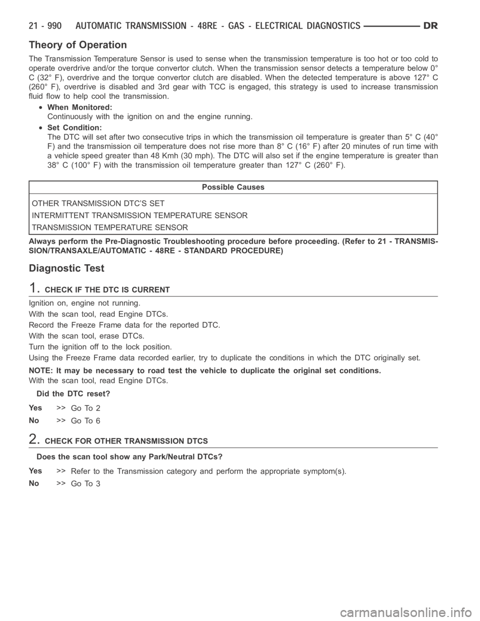
The Transmission Temperature Sensor is used to sense when the transmissiontemperatureistoohotortoocoldto
operate overdrive and/or the torque convertor clutch. When the transmission sensor detects a temperature below 0°
C (32° F), overdrive and the torque convertor clutch are disabled. When thedetected temperature is above 127° C
(260° F), overdrive is disabled and 3rd gear with TCC is engaged, this strategy is used to increase transmission
fluid flow to help cool the transmission.
When Monitored:
Continuously with the ignition on and the engine running.
Set Condition:
The DTC will set after two consecutive trips in which the transmission oil temperature is greater than 5° C (40°
F) and the transmission oil temperature does not rise more than 8° C (16° F) after 20 minutes of run time with
a vehicle speed greater than 48 Kmh (30 mph). The DTC will also set if the engine temperature is greater than
38° C (100° F) with the transmission oil temperature greater than 127° C (260° F).
Possible Causes
OTHER TRANSMISSION DTC’S SET
INTERMITTENT TRANSMISSION TEMPERATURE SENSOR
TRANSMISSION TEMPERATURE SENSOR
Always perform the Pre-Diagnostic Troubleshooting procedure before proceeding. (Refer to 21 - TRANSMIS-
SION/TRANSAXLE/AUTOMATIC - 48RE - STANDARD PROCEDURE)
Diagnostic Test
1.CHECK IF THE DTC IS CURRENT
Ignition on, engine not running.
With the scan tool, read Engine DTCs.
Record the Freeze Frame data for the reported DTC.
With the scan tool, erase DTCs.
Turn the ignition off to the lock position.
Using the Freeze Frame data recorded earlier, try to duplicate the conditions in which the DTC originally set.
NOTE: It may be necessary to road test the vehicle to duplicate the originalset conditions.
With the scan tool, read Engine DTCs.
Did the DTC reset?
Ye s>>
Go To 2
No>>
Go To 6
2.CHECK FOR OTHER TRANSMISSION DTCS
Does the scan tool show any Park/Neutral DTCs?
Ye s>>
Refer to the Transmission category and perform the appropriate symptom(s).
No>>
Go To 3
Page 3512 of 5267

3.COMPARE THE TRANSMISSION TEMPERATURE TO ENGINE COOLANT TEMPERATURE
NOTE: To test the transmission temperature sensor, the engine and transmission temperature must be at or
below 29.4° C (85° F).
With the scan tool, read the Transmission and Engine temperatures.
Is the transmission temperature within 5° C (9° F) of the engine coolant temperature?
Ye s>>
Go To 4
No>>
Go To 5
4.CHECK IF THE TRANSMISSION TEMPERATURE INCREASES 15 DEGREES OVER 10 MINUTEPERIOD
NOTE: To test the transmission temperature sensor, the engine and transmission temperature must be at or
below 29.4° C (85° F).
CAUTION: Apply the parking brake.
Start the engine, firmly apply the brakes and allow the engine to idle in Drive.
With the scan tool, monitor the Transmission Temperature.
NOTE: If the transmission temperature sensor is working properly, the transmission temperature should rise
at least 8° C (15° F) within a ten minute period.
Did the transmission temperature increase at a steady rate and rise at least 8° C (15° F) over a 10
minute period?
Ye s>>
Go To 6
No>>
Go To 5
5.CHECK THE TRANSMISSION TEMPERATURE SENSOR
TYPICAL VALUES FOR TRANSMISSION TEMPERATURE SENSOR
TEMPERATURE MIN TO MAX OHM RANGE
-40° C (-40° F) 1094 to 1176 ohms
0.0° C (32° F) 1587 to 1672 ohms
25° C (77° F) 1960 to 2040 ohms
70° C (158° F) 2709 to 2860 ohms
0° C (212° F) 3284 to 3500 ohms
120° C (120° F) 3684 to 3950 ohms
150° C (302° F) 4110 to 4450 ohms
Page 3513 of 5267

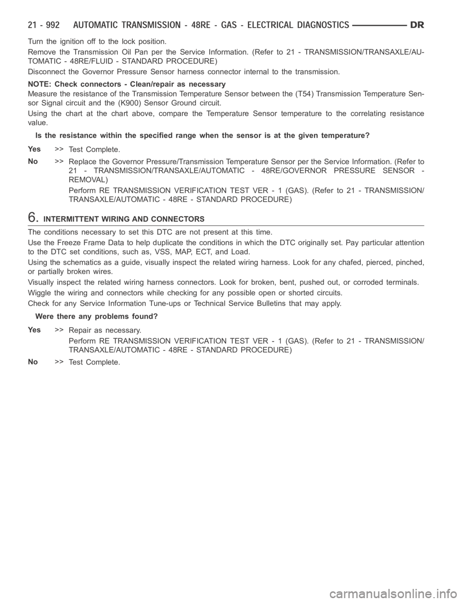
Turn the ignition off to the lock position.
Remove the Transmission Oil Pan per the Service Information. (Refer to 21 -TRANSMISSION/TRANSAXLE/AU-
TOMATIC - 48RE/FLUID - STANDARD PROCEDURE)
Disconnect the Governor Pressure Sensor harness connector internal to the transmission.
NOTE: Check connectors - Clean/repair as necessary
Measure the resistance of the Transmission Temperature Sensor between the (T54) Transmission Temperature Sen-
sor Signal circuit and the (K900) Sensor Ground circuit.
Using the chart at the chart above, compare the Temperature Sensor temperature to the correlating resistance
value.
Is the resistance within the specified range when the sensor is at the giventemperature?
Ye s>>
Te s t C o m p l e t e .
No>>
Replace the Governor Pressure/Transmission Temperature Sensor per the Service Information. (Refer to
21 - TRANSMISSION/TRANSAXLE/AUTOMATIC - 48RE/GOVERNOR PRESSURE SENSOR-
REMOVAL)
Perform RE TRANSMISSION VERIFICATION TEST VER - 1 (GAS). (Refer to 21 - TRANSMISSION/
TRANSAXLE/AUTOMATIC - 48RE - STANDARD PROCEDURE)
6.INTERMITTENT WIRING AND CONNECTORS
The conditions necessary to set this DTC are not present at this time.
Use the Freeze Frame Data to help duplicate the conditions in which the DTC originally set. Pay particular attention
to the DTC set conditions, such as, VSS, MAP, ECT, and Load.
Using the schematics as a guide, visually inspect the related wiring harness. Look for any chafed, pierced, pinched,
or partially broken wires.
Visually inspect the related wiring harness connectors. Look for broken,bent, pushed out, or corroded terminals.
Wiggle the wiring and connectors while checking for any possible open or shorted circuits.
Check for any Service Information Tune-ups or Technical Service Bulletins that may apply.
Were there any problems found?
Ye s>>
Repair as necessary.
Perform RE TRANSMISSION VERIFICATION TEST VER - 1 (GAS). (Refer to 21 - TRANSMISSION/
TRANSAXLE/AUTOMATIC - 48RE - STANDARD PROCEDURE)
No>>
Te s t C o m p l e t e .
Page 3514 of 5267
P0712-TRANS TEMP SENSOR VOLTAGE TOO LOW (GAS)
For a complete wiring diagramRefer to Section 8W