Page 3435 of 5267
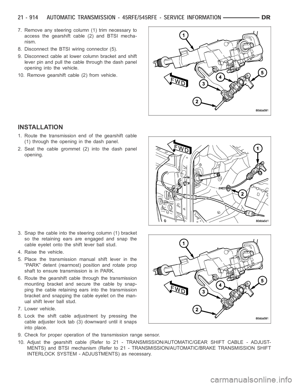
7. Remove any steering column (1) trim necessary to
access the gearshift cable (2) and BTSI mecha-
nism.
8. Disconnect the BTSI wiring connector (5).
9. Disconnect cable at lower column bracket and shift
lever pin and pull the cable through the dash panel
opening into the vehicle.
10. Remove gearshift cable (2) from vehicle.
INSTALLATION
1. Route the transmission end of the gearshift cable
(1) through the opening in the dash panel.
2. Seat the cable grommet (2) into the dash panel
opening.
3. Snap the cable into the steering column (1) bracket
so the retaining ears are engaged and snap the
cable eyelet onto the shift lever ball stud.
4. Raise the vehicle.
5. Place the transmission manual shift lever in the
“PARK” detent (rearmost) position and rotate prop
shaft to ensure transmission is in PARK.
6. Route the gearshift cable through the transmission
mounting bracket and secure the cable by snap-
ping the cable retaining ears into the transmission
bracket and snapping the cable eyelet on the man-
ual shift lever ball stud.
7. Lower vehicle.
8. Lock the shift cable adjustment by pressing the
cable adjuster lock tab (3) downward until it snaps
into place.
9. Check for proper operation of the transmission range sensor.
10. Adjust the gearshift cable (Refer to 21 - TRANSMISSION/AUTOMATIC/GEAR SHIFT CABLE - ADJUST-
MENTS) and BTSI mechanism (Refer to 21 - TRANSMISSION/AUTOMATIC/BRAKE TRANSMISSION SHIFT
INTERLOCK SYSTEM - ADJUSTMENTS) as necessary.
Page 3436 of 5267
ADJUSTMENTS - GEARSHIFT CABLE
Check adjustment by starting the engine in PARK and NEUTRAL. Adjustment isCORRECT if the engine starts only
in these positions. Adjustment is INCORRECT if the engine starts in one butnot both positions. If the engine starts
in any position other than PARK or NEUTRAL, or if the engine will not start atall, the transmission range sensor
may be faulty.
Gearshift Adjustment Procedure
1. Shift transmission into PARK.
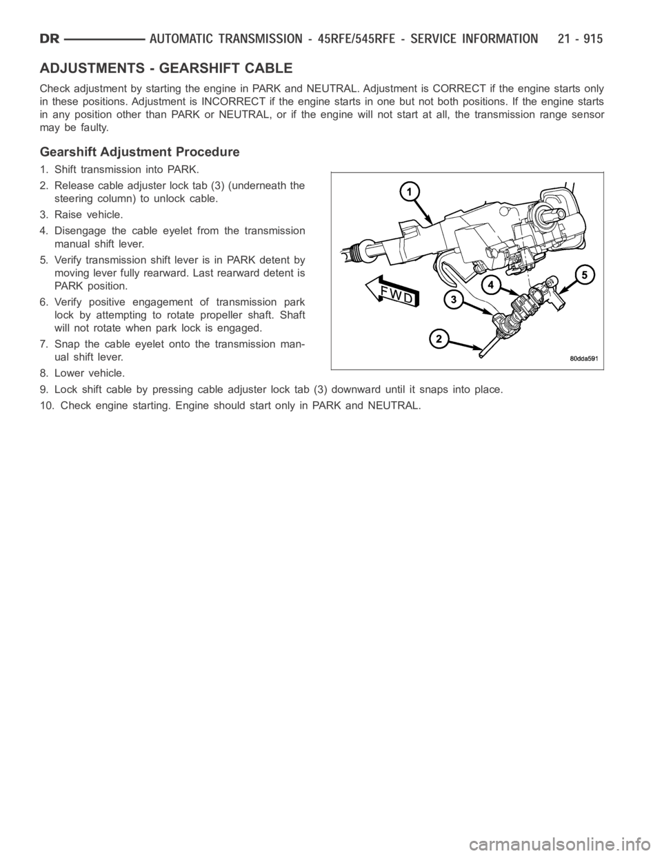
2. Release cable adjuster lock tab (3) (underneath the
steering column) to unlock cable.
3. Raise vehicle.
4. Disengage the cable eyelet from the transmission
manual shift lever.
5. Verify transmission shift lever is in PARK detent by
moving lever fully rearward. Last rearward detent is
PARK position.
6. Verify positive engagement of transmission park
lock by attempting to rotate propeller shaft. Shaft
will not rotate when park lock is engaged.
7. Snap the cable eyelet onto the transmission man-
ual shift lever.
8. Lower vehicle.
9. Lock shift cable by pressing cable adjuster lock tab (3) downward until it snaps into place.
10. Check engine starting. Engine should start only in PARK and NEUTRAL.
Page 3453 of 5267
SENSOR-INPUT SPEED
DESCRIPTION
The Input and Output Speed Sensors are two-wire magnetic pickup devices that generate AC signals as rotation
occurs. They are mounted in the left side of the transmission case and are considered primary inputs to the Trans-
mission Control Module (TCM).
OPERATION
The Input Speed Sensor provides information on how fast the input shaft is rotating. As the teeth of the input clutch
hub pass by the sensor coil, an AC voltage is generated and sent to the TCM. The TCM interprets this information
as input shaft rpm.
The Output Speed Sensor generates an AC signal in a similar fashion, thoughitscoilisexcitedbyrotationofthe
rear planetary carrier lugs. The TCM interprets this information as outputshaftrpm.
The TCM compares the input and output speed signals to determine the following:
Transmission gear ratio
Speed ratio error detection
CVI calculation
The TCM also compares the input speed signal and the engine speed signal to determine the following:
Torque converter clutch slippage
Torque converter element speed ratio
REMOVAL
1. Raise vehicle.
2. Place a suitable fluid catch pan under the transmis-
sion.
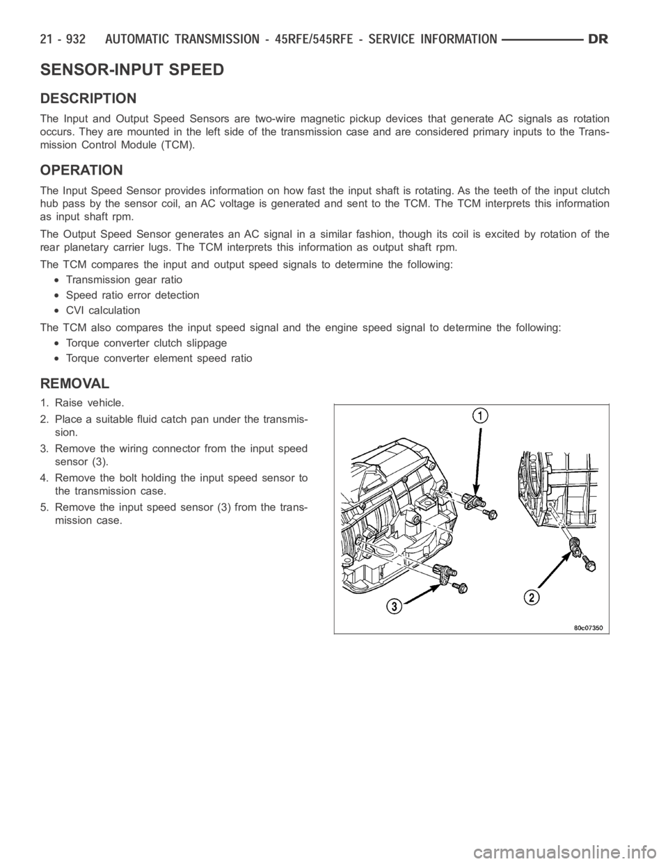
3. Remove the wiring connector from the input speed
sensor (3).
4. Remove the bolt holding the input speed sensor to
the transmission case.
5. Remove the input speed sensor (3) from the trans-
mission case.
Page 3454 of 5267
INSTALLATION
1. Install the input speed sensor (3) into the transmis-
sion case.
2. Install the bolt to hold the input speed sensor (3)
into the transmission case. Tighten the bolt to 12
Nꞏm (105 in.lbs.).
3. Install the wiring connector onto the input speed
sensor.
4. Verify the transmission fluid level. Add fluid as nec-
essary.
5. Lower vehicle.
Page 3455 of 5267
SENSOR-LINE PRESSURE
DESCRIPTION
The TCM utilizes a closed-loop system to control transmission line pressure. The system contains a variable force
style solenoid, the Pressure Control Solenoid, mounted on the side of the solenoid and pressure switch assembly.
The solenoid is duty cycle controlled by the TCM to vent the unnecessary line pressure supplied by the oil pump
back to the sump. The system also contains a variable pressure style sensor, the Line Pressure Sensor, which is a
direct input to the TCM. The line pressure solenoid monitors the transmission line pressure and completes the feed-
back loop to the TCM. The TCM uses this information to adjust its control of the pressure control solenoid to
achieve the desired line pressure.
OPERATION
The TCM calculates the desired line pressure based upon inputs from the transmission and engine. The TCM cal-
culates the torque input to the transmission and uses that information as the primary input to the calculation. The
line pressure is set to a predetermined value during shifts and when the transmission is in the PARK and NEUTRAL
positions. This is done to ensure consistent shift quality. During all other operation, the actual line pressure is com-
pared to the desired line pressure and adjustments are made to the pressurecontrol solenoid duty cycle.
REMOVAL
1. Raise vehicle.
2. Place a suitable fluid catch pan under the transmis-
sion.
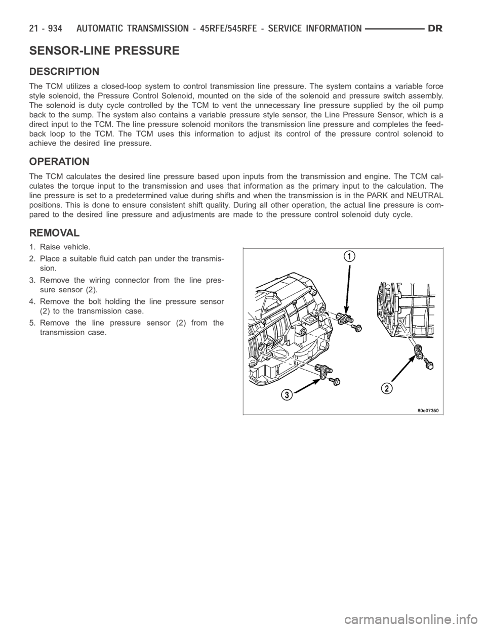
3. Remove the wiring connector from the line pres-
sure sensor (2).
4. Remove the bolt holding the line pressure sensor
(2) to the transmission case.
5. Remove the line pressure sensor (2) from the
transmission case.
Page 3456 of 5267
INSTALLATION
1. Install the line pressure sensor (2) into the trans-
mission case.
2. Install the bolt to hold the line pressure sensor (2)
into the transmission case. Tighten the bolt to 12
Nꞏm (105 in.lbs.).
3. Install the wiring connector onto the line pressure
sensor (2).
4. Verify the transmission fluid level. Add fluid as nec-
essary.
5. Lower vehicle.
Page 3472 of 5267
SENSOR-OUTPUT SPEED
DESCRIPTION
The Input and Output Speed Sensors are two-wire magnetic pickup devices that generate AC signals as rotation
occurs. They are mounted in the left side of the transmission case and are considered primary inputs to the Trans-
mission Control Module (TCM).
OPERATION
The Input Speed Sensor provides information on how fast the input shaft is rotating. As the teeth of the input clutch
hub pass by the sensor coil, an AC voltage is generated and sent to the TCM. The TCM interprets this information
as input shaft rpm.
The Output Speed Sensor generates an AC signal in a similar fashion, thoughitscoilisexcitedbyrotationofthe
rear planetary carrier lugs. The TCM interprets this information as outputshaftrpm.
The TCM compares the input and output speed signals to determine the following:
Transmission gear ratio
Speed ratio error detection
CVI calculation
The TCM also compares the input speed signal and the engine speed signal to determine the following:
Torque converter clutch slippage
Torque converter element speed ratio
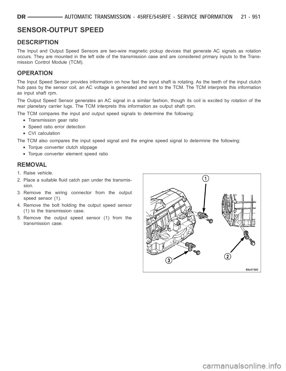
REMOVAL
1. Raise vehicle.
2. Place a suitable fluid catch pan under the transmis-
sion.
3. Remove the wiring connector from the output
speed sensor (1).
4. Remove the bolt holding the output speed sensor
(1) to the transmission case.
5. Remove the output speed sensor (1) from the
transmission case.
Page 3473 of 5267
INSTALLATION
1. Install the output speed sensor (1) into the trans-
mission case.
2. Install the bolt to hold the output speed sensor (1)
into the transmission case. Tighten the bolt to 12
Nꞏm (105 in.lbs.).
3. Install the wiring connector onto the output speed
sensor (1).
4. Verify the transmission fluid level. Add fluid as nec-
essary.
5. Lower vehicle.