2006 DODGE RAM SRT-10 lock
[x] Cancel search: lockPage 3796 of 5267
SECOND GEAR POWERFLOW
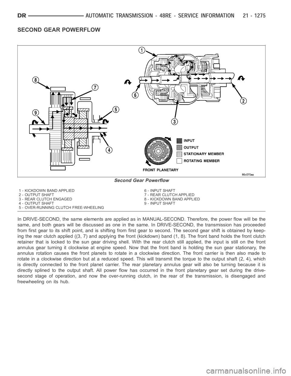
In DRIVE-SECOND, the same elements are applied as in MANUAL-SECOND. Therefore, the power flow will be the
same, and both gears will be discussed as one in the same. In DRIVE-SECOND, the transmission has proceeded
from first gear to its shift point, and is shifting from first gear to second. The second gear shift is obtained by keep-
ing the rear clutch applied ((3, 7) and applying the front (kickdown) band (1, 8). The front band holds the front clutch
retainer that is locked to the sun gear driving shell. With the rear clutch still applied, the input is still on the front
annulus gear turning it clockwise at engine speed. Now that the front band is holding the sun gear stationary, the
annulus rotation causes the front planets to rotate in a clockwise direction. The front carrier is then also made to
rotate in a clockwise direction but at a reduced speed. This will transmit the torque to the output shaft (2, 4), which
is directly connected to the front planet carrier. The rear planetary annulus gear will also be turning because it is
directly splined to the output shaft. All power flow has occurred in the front planetary gear set during the drive-
second stage of operation, and now the over-running clutch, in the rear of the transmission, is disengaged and
freewheeling on its hub.
Second Gear Powerflow
1 - KICKDOWN BAND APPLIED 6 - INPUT SHAFT
2 - OUTPUT SHAFT 7 - REAR CLUTCH APPLIED
3 - REAR CLUTCH ENGAGED 8 - KICKDOWN BAND APPLIED
4 - OUTPUT SHAFT 9 - INPUT SHAFT
5 - OVER-RUNNING CLUTCH FREE-WHEELING
Page 3797 of 5267
DIRECT DRIVE POWERFLOW
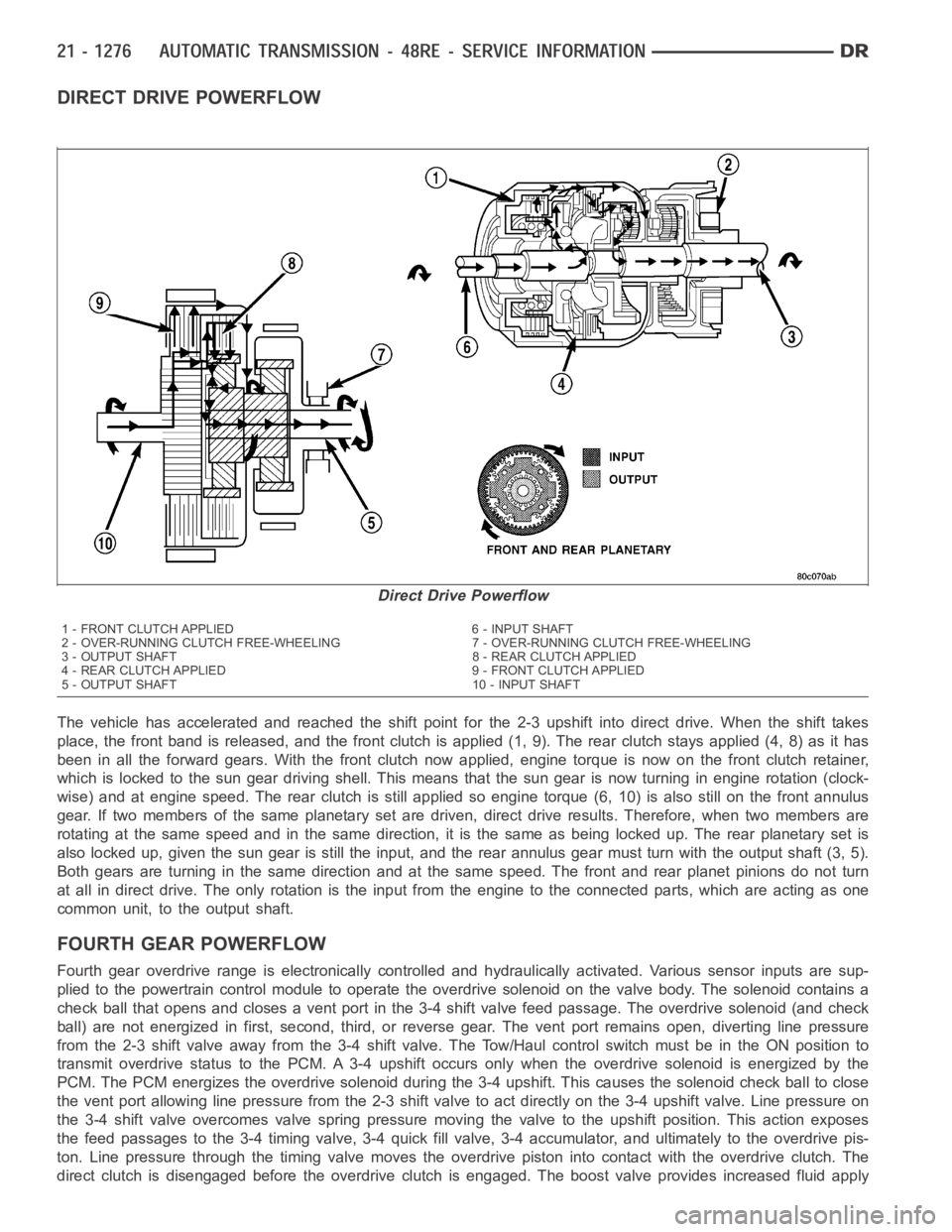
The vehicle has accelerated and reached the shift point for the 2-3 upshiftinto direct drive. When the shift takes
place, the front band is released, and the front clutch is applied (1, 9). The rear clutch stays applied (4, 8) as it has
been in all the forward gears. With the front clutch now applied, engine torque is now on the front clutch retainer,
which is locked to the sun gear drivingshell. This means that the sun gear isnow turning in engine rotation (clock-
wise) and at engine speed. The rear clutch is still applied so engine torque(6, 10) is also still on the front annulus
gear. If two members of the same planetary set are driven, direct drive results. Therefore, when two members are
rotating at the same speed and in the same direction, it is the same as being locked up. The rear planetary set is
also locked up, given the sun gear is still the input, and the rear annulus gear must turn with the output shaft (3, 5).
Both gears are turning in the same direction and at the same speed. The frontand rear planet pinions do not turn
at all in direct drive. The only rotation is the input from the engine to the connected parts, which are acting as one
common unit, to the output shaft.
FOURTHGEARPOWERFLOW
Fourth gear overdrive range is electronically controlled and hydraulically activated. Various sensor inputs are sup-
plied to the powertrain control module to operate the overdrive solenoid on the valve body. The solenoid contains a
check ball that opens and closes a vent port in the 3-4 shift valve feed passage. The overdrive solenoid (and check
ball) are not energized in first, second, third, or reverse gear. The vent port remains open, diverting line pressure
from the 2-3 shift valve away from the 3-4 shift valve. The Tow/Haul controlswitch must be in the ON position to
transmit overdrive status to the PCM. A 3-4 upshift occurs only when the overdrive solenoid is energized by the
PCM. The PCM energizes the overdrive solenoid during the 3-4 upshift. Thiscauses the solenoid check ball to close
the vent port allowing line pressure from the 2-3 shift valve to act directly on the 3-4 upshift valve. Line pressure on
the 3-4 shift valve overcomes valve spring pressure moving the valve to theupshift position. This action exposes
the feed passages to the 3-4 timing valve, 3-4 quick fill valve, 3-4 accumulator, and ultimately to the overdrive pis-
ton. Line pressure through the timing valve moves the overdrive piston into contact with the overdrive clutch. The
direct clutch is disengaged before the overdrive clutch is engaged. The boost valve provides increased fluid apply
Direct Drive Powerflow
1 - FRONT CLUTCH APPLIED 6 - INPUT SHAFT
2 - OVER-RUNNING CLUTCH FREE-WHEELING 7 - OVER-RUNNING CLUTCH FREE-WHEELING
3 - OUTPUT SHAFT 8 - REAR CLUTCH APPLIED
4 - REAR CLUTCH APPLIED 9 - FRONT CLUTCH APPLIED
5 - OUTPUT SHAFT 10 - INPUT SHAFT
Page 3810 of 5267
CONDITION POSSIBLE CAUSES CORRECTION
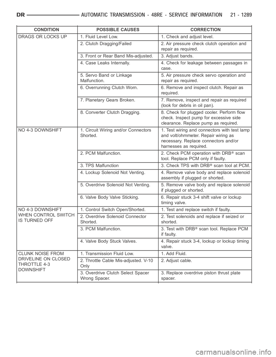
DRAGS OR LOCKS UP 1. Fluid Level Low. 1. Check and adjust level.
2. Clutch Dragging/Failed 2. Air pressure check clutch operation and
repair as required.
3. Front or Rear Band Mis-adjusted. 3. Adjust bands.
4. Case Leaks Internally. 4. Check for leakage between passages in
case.
5. Servo Band or Linkage
Malfunction.5. Air pressure check servo operation and
repair as required.
6. Overrunning Clutch Worn. 6. Remove and inspect clutch. Repair as
required.
7. Planetary Gears Broken. 7. Remove, inspect and repair as required
(look for debris in oil pan).
8. Converter Clutch Dragging. 8. Check for plugged cooler. Perform flow
check. Inspect pump for excessive side
clearance. Replace pump as required.
NO 4-3 DOWNSHIFT 1. Circuit Wiring and/or Connectors
Shorted.1. Test wiring and connectors with test lamp
and volt/ohmmeter. Repair wiring as
necessary. Replace connectors and/or
harnesses as required.
2. PCM Malfunction. 2. Check PCM operation with DRB
scan
tool. Replace PCM only if faulty.
3. TPS Malfunction 3. Check TPS with DRB
scan tool at PCM.
4. Lockup Solenoid Not Venting. 4. Remove valve body and replace solenoid
assembly if plugged or shorted.
5. Overdrive Solenoid Not Venting. 5. Remove valve body and replace solenoid
if plugged or shorted.
6. Valve Body Valve Sticking. 6. Repair stuck 3-4 shift valve or lockup
timing valve.
NO 4-3 DOWNSHIFT
WHEN CONTROL SWITCH
IS TURNED OFF1. Control Switch Open/Shorted. 1. Test and replace switch if faulty.
2. Overdrive Solenoid Connector
Shorted.2. Test solenoids and replace if seized or
shorted.
3. PCM Malfunction. 3. Test with DRB
scan tool. Replace PCM
if faulty.
4. Valve Body Stuck Valves. 4. Repair stuck 3-4, lockup or lockup timing
valve.
CLUNK NOISE FROM
DRIVELINE ON CLOSED
THROTTLE 4-3
DOWNSHIFT1. Transmission Fluid Low. 1. Add Fluid.
2. Throttle Cable Mis-adjusted. V-10
Only2. Adjust cable.
3. Overdrive Clutch Select Spacer
Wrong Spacer.3. Replace overdrive piston thrust plate
spacer.
Page 3811 of 5267
CONDITION POSSIBLE CAUSES CORRECTION
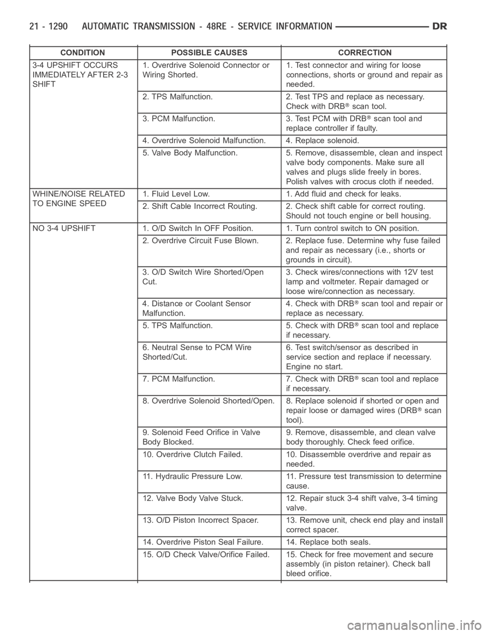
3-4 UPSHIFT OCCURS
IMMEDIATELY AFTER 2-3
SHIFT1. Overdrive Solenoid Connector or
Wiring Shorted.1. Test connector and wiring for loose
connections, shorts or ground and repair as
needed.
2. TPS Malfunction. 2. Test TPS and replace as necessary.
Check with DRB
scan tool.
3. PCM Malfunction. 3. Test PCM with DRB
scan tool and
replace controller if faulty.
4. Overdrive Solenoid Malfunction. 4. Replace solenoid.
5. Valve Body Malfunction. 5. Remove, disassemble, clean and inspect
valve body components. Make sure all
valves and plugs slide freely in bores.
Polish valves with crocus cloth if needed.
WHINE/NOISE RELATED
TO ENGINE SPEED1. Fluid Level Low. 1. Add fluid and check for leaks.
2. Shift Cable Incorrect Routing. 2. Check shift cable for correct routing.
Should not touch engine or bell housing.
NO3-4UPSHIFT 1.O/DSwitchInOFFPosition. 1.TurncontrolswitchtoONposition.
2. Overdrive Circuit Fuse Blown. 2. Replace fuse. Determine why fuse failed
and repair as necessary (i.e., shorts or
grounds in circuit).
3. O/D Switch Wire Shorted/Open
Cut.3. Check wires/connections with 12V test
lamp and voltmeter. Repair damaged or
loose wire/connection as necessary.
4. Distance or Coolant Sensor
Malfunction.4. Check with DRB
scan tool and repair or
replace as necessary.
5. TPS Malfunction. 5. Check with DRB
scan tool and replace
if necessary.
6. Neutral Sense to PCM Wire
Shorted/Cut.6. Test switch/sensor as described in
service section and replace if necessary.
Engine no start.
7. PCM Malfunction. 7. Check with DRB
scan tool and replace
if necessary.
8. Overdrive Solenoid Shorted/Open. 8. Replace solenoid if shorted or openand
repair loose or damaged wires (DRB
scan
tool).
9. Solenoid Feed Orifice in Valve
Body Blocked.9. Remove, disassemble, and clean valve
body thoroughly. Check feed orifice.
10. Overdrive Clutch Failed. 10. Disassemble overdrive and repair as
needed.
11. Hydraulic Pressure Low. 11. Pressure test transmission to determine
cause.
12. Valve Body Valve Stuck. 12. Repair stuck 3-4 shift valve, 3-4 timing
valve.
13. O/D Piston Incorrect Spacer. 13. Remove unit, check end play and install
correct spacer.
14. Overdrive Piston Seal Failure. 14. Replace both seals.
15. O/D Check Valve/Orifice Failed. 15. Check for free movement and secure
assembly (in piston retainer). Check ball
bleed orifice.
Page 3812 of 5267
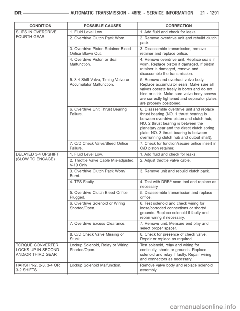
CONDITION POSSIBLE CAUSES CORRECTION
SLIPS IN OVERDRIVE
FOURTH GEAR1. Fluid Level Low. 1. Add fluid and check for leaks.
2. Overdrive Clutch Pack Worn. 2. Remove overdrive unit and rebuild clutch
pack.
3. Overdrive Piston Retainer Bleed
Orifice Blown Out.3. Disassemble transmission, remove
retainer and replace orifice.
4. Overdrive Piston or Seal
Malfunction.4. Remove overdrive unit. Replace seals if
worn. Replace piston if damaged. If piston
retainer is damaged, remove and
disassemble the transmission.
5. 3-4 Shift Valve, Timing Valve or
Accumulator Malfunction.5. Remove and overhaul valve body.
Replace accumulator seals. Make sure all
valves operate freely in bores and do not
bind or stick. Make sure valve body screws
are correctly tightened and separator plates
are properly positioned.
6. Overdrive Unit Thrust Bearing
Failure.6. Disassemble overdrive unit and replace
thrust bearing (NO. 1 thrust bearing is
between overdrive piston and clutch hub;
NO. 2 thrust bearing is between the
planetary gear and the direct clutch spring
plate; NO. 3 thrust bearing is between
overrunning clutch hub and output shaft).
7. O/D Check Valve/Bleed Orifice
Failure.7. Check for function/secure orifice insert in
O/D piston retainer.
DELAYED 3-4 UPSHIFT
(SLOW TO ENGAGE)1. Fluid Level Low. 1. Add fluid and check for leaks.
2. Throttle Valve Cable Mis-adjusted.
V- 1 0 O n l y2. Adjust throttle valve cable.
3. Overdrive Clutch Pack Worn/
Burnt.3. Remove unit and rebuild clutch pack.
4. TPS Faulty. 4. Test with DRB
scan tool and replace as
necessary
5. Overdrive Clutch Bleed Orifice
Plugged.5. Disassemble transmission and replace
orifice.
6. Overdrive Solenoid or Wiring
Shorted/Open.6. Test solenoid and check wiring for
loose/corroded connections or shorts/
grounds. Replace solenoid if faulty and
repair wiring if necessary.
7. Overdrive Excess Clearance. 7. Remove unit. Measure end play and
select proper spacer.
8. O/D Check Valve Missing or
Stuck.8. Check for presence of check valve.
Repair or replace as required.
TORQUE CONVERTER
LOCKS UP IN SECOND
AND/OR THIRD GEARLockup Solenoid, Relay or Wiring
Shorted/Open.Test solenoid, relay and wiring for
continuity, shorts or grounds. Replace
solenoid and relay if faulty. Repair wiring
and connectors as necessary.
HARSH 1-2, 2-3, 3-4 OR
3-2 SHIFTSLockup Solenoid Malfunction. Remove valve body and replace solenoid
assembly.
Page 3815 of 5267
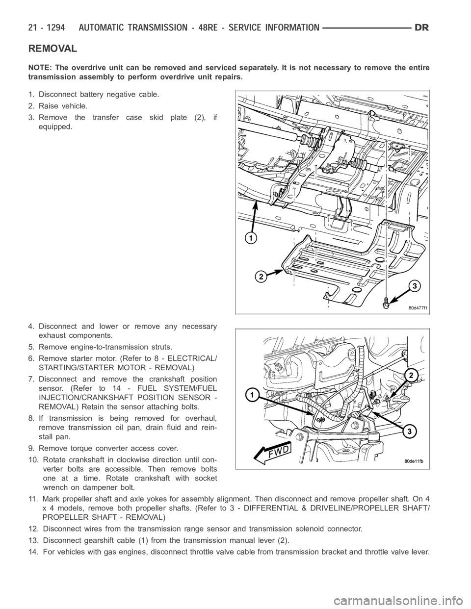
REMOVAL
NOTE: The overdrive unit can be removed and serviced separately. It is not necessary to remove the entire
transmission assembly to perform overdrive unit repairs.
1. Disconnect battery negative cable.
2. Raise vehicle.
3. Remove the transfer case skid plate (2), if
equipped.
4. Disconnect and lower or remove any necessary
exhaust components.
5. Remove engine-to-transmission struts.
6. Remove starter motor. (Refer to 8 - ELECTRICAL/
STARTING/STARTER MOTOR - REMOVAL)
7. Disconnect and remove the crankshaft position
sensor. (Refer to 14 - FUEL SYSTEM/FUEL
INJECTION/CRANKSHAFT POSITION SENSOR -
REMOVAL) Retain the sensor attaching bolts.
8. If transmission is being removed for overhaul,
remove transmission oil pan, drain fluid and rein-
stall pan.
9. Remove torque converter access cover.
10. Rotate crankshaft in clockwise direction until con-
verter bolts are accessible. Then remove bolts
one at a time. Rotate crankshaft with socket
wrench on dampener bolt.
11. Mark propeller shaft and axle yokes for assembly alignment. Then disconnect and remove propeller shaft. On 4
x 4 models, remove both propeller shafts. (Refer to 3 - DIFFERENTIAL & DRIVELINE/PROPELLER SHAFT/
PROPELLER SHAFT - REMOVAL)
12. Disconnect wires from the transmission range sensor and transmissionsolenoid connector.
13. Disconnect gearshift cable (1) from the transmission manual lever (2).
14. For vehicles with gas engines, disconnect throttle valve cable from transmission bracket andthrottle valve lever.
Page 3816 of 5267
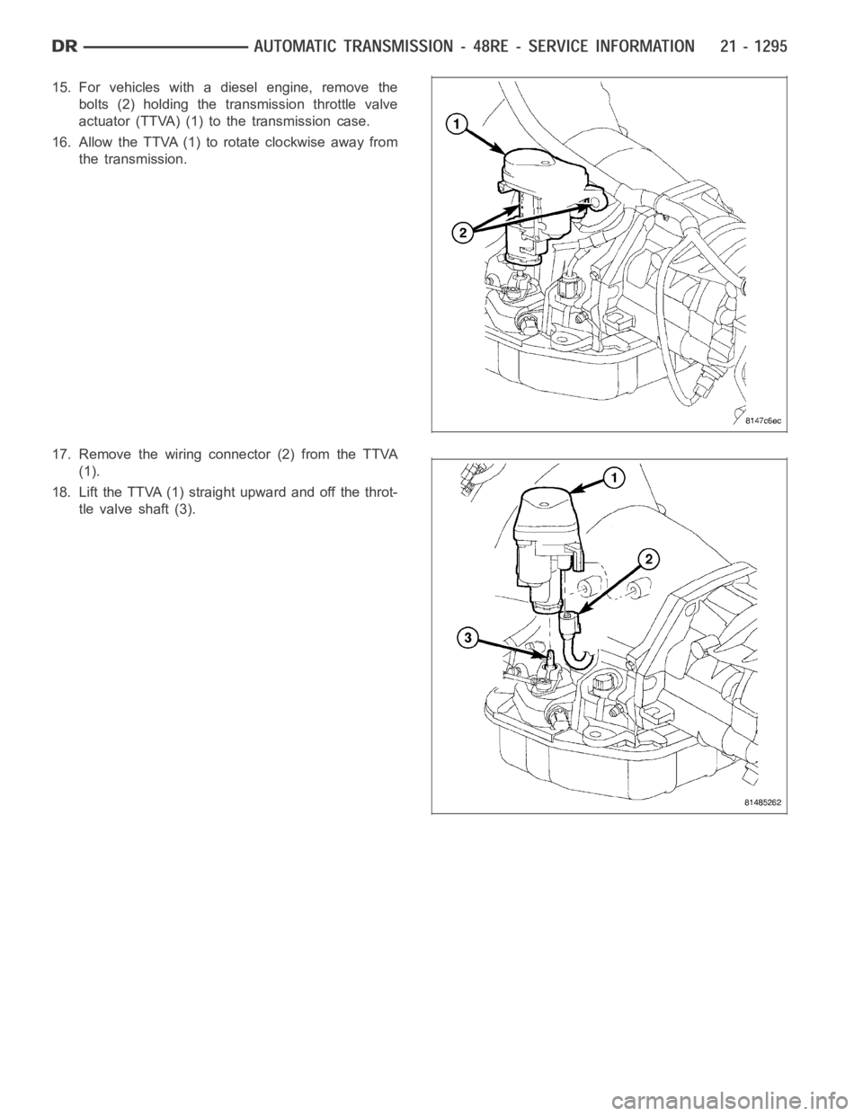
15. For vehicles with a diesel engine, remove the
bolts (2) holding the transmission throttle valve
actuator (TTVA) (1) to the transmission case.
16. Allow the TTVA (1) to rotate clockwise away from
the transmission.
17. Remove the wiring connector (2) from the TTVA
(1).
18. Lift the TTVA (1) straight upward and off the throt-
tle valve shaft (3).
Page 3818 of 5267
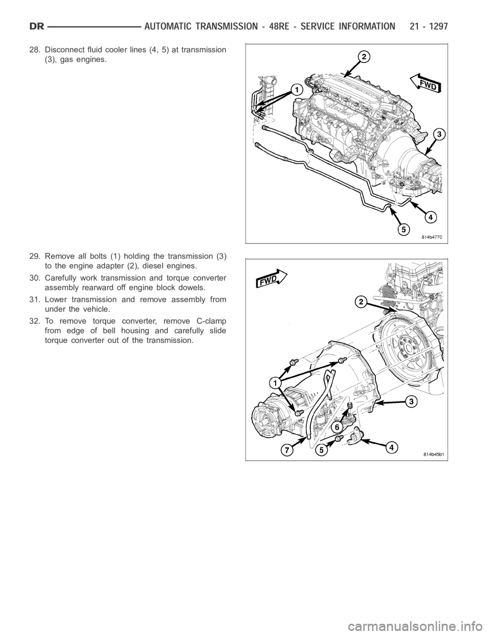
28. Disconnect fluid cooler lines (4, 5) at transmission
(3), gas engines.
29. Remove all bolts (1) holding the transmission (3)
to the engine adapter (2), diesel engines.
30. Carefully work transmission and torque converter
assembly rearward off engine block dowels.
31. Lower transmission and remove assembly from
under the vehicle.
32. To remove torque converter, remove C-clamp
from edge of bell housing and carefully slide
torque converter out of the transmission.