2006 DODGE RAM SRT-10 lock
[x] Cancel search: lockPage 3779 of 5267
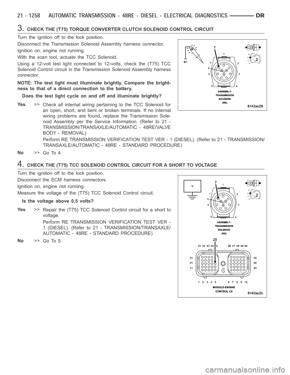
3.CHECK THE (T75) TORQUE CONVERTER CLUTCH SOLENOID CONTROL CIRCUIT
Turn the ignition off to the lock position.
Disconnect the Transmission Solenoid Assembly harness connector.
Ignition on, engine not running.
With the scan tool, actuate the TCC Solenoid.
Using a 12-volt test light connected to 12-volts, check the (T75) TCC
Solenoid Control circuit in the Transmission Solenoid Assembly harness
connector.
NOTE: The test light must illuminate brightly. Compare the bright-
ness to that of a direct connection to the battery.
Does the test light cycle on and off and illuminate brightly?
Ye s>>
Check all internal wiring pertaining to the TCC Solenoid for
an open, short, and bent or broken terminals. If no internal
wiring problems are found, replace the Transmission Sole-
noid Assembly per the Service Information. (Refer to 21 -
TRANSMISSION/TRANSAXLE/AUTOMATIC - 48RE/VALVE
BODY - REMOVAL)
Perform RE TRANSMISSION VERIFICATION TEST VER - 1 (DIESEL). (Refer to 21 - TRANSMISSION/
TRANSAXLE/AUTOMATIC - 48RE - STANDARD PROCEDURE)
No>>
Go To 4
4.CHECK THE (T75) TCC SOLENOID CONTROL CIRCUIT FOR A SHORT TO VOLTAGE
Turn the ignition off to the lock position.
Disconnect the ECM harness connectors.
Ignition on, engine not running.
Measure the voltage of the (T75) TCC Solenoid Control circuit.
Is the voltage above 0.5 volts?
Ye s>>
Repair the (T75) TCC Solenoid Control circuit for a short to
voltage.
Perform RE TRANSMISSION VERIFICATION TEST VER -
1 (DIESEL). (Refer to 21 - TRANSMISSION/TRANSAXLE/
AUTOMATIC - 48RE - STANDARD PROCEDURE)
No>>
Go To 5
Page 3780 of 5267
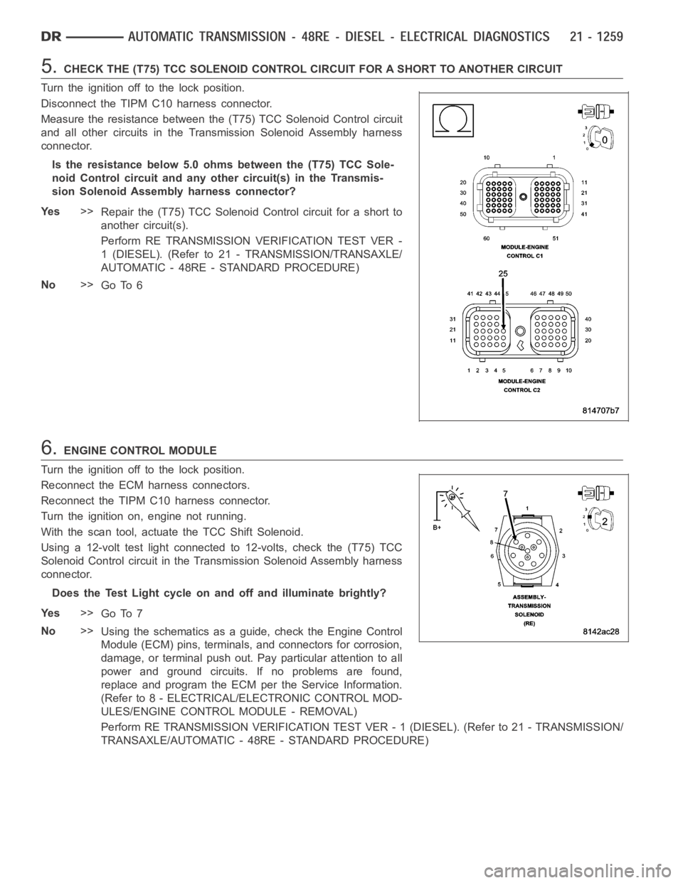
5.CHECK THE (T75) TCC SOLENOID CONTROL CIRCUIT FOR A SHORT TO ANOTHER CIRCUIT
Turn the ignition off to the lock position.
Disconnect the TIPM C10 harness connector.
Measure the resistance between the (T75) TCC Solenoid Control circuit
and all other circuits in the Transmission Solenoid Assembly harness
connector.
Is the resistance below 5.0 ohms between the (T75) TCC Sole-
noid Control circuit and any other circuit(s) in the Transmis-
sion Solenoid Assembly harness connector?
Ye s>>
Repair the (T75) TCC Solenoid Control circuit for a short to
another circuit(s).
Perform RE TRANSMISSION VERIFICATION TEST VER -
1 (DIESEL). (Refer to 21 - TRANSMISSION/TRANSAXLE/
AUTOMATIC - 48RE - STANDARD PROCEDURE)
No>>
Go To 6
6.ENGINE CONTROL MODULE
Turn the ignition off to the lock position.
Reconnect the ECM harness connectors.
Reconnect the TIPM C10 harness connector.
Turn the ignition on, engine not running.
With the scan tool, actuate the TCC Shift Solenoid.
Using a 12-volt test light connected to 12-volts, check the (T75) TCC
Solenoid Control circuit in the Transmission Solenoid Assembly harness
connector.
Does the Test Light cycle on and off and illuminate brightly?
Ye s>>
Go To 7
No>>
Using the schematics as a guide, check the Engine Control
Module (ECM) pins, terminals, and connectors for corrosion,
damage, or terminal push out. Pay particular attention to all
power and ground circuits. If no problems are found,
replace and program the ECM per the Service Information.
(Refer to 8 - ELECTRICAL/ELECTRONIC CONTROL MOD-
ULES/ENGINE CONTROL MODULE - REMOVAL)
Perform RE TRANSMISSION VERIFICATION TEST VER - 1 (DIESEL). (Refer to 21 - TRANSMISSION/
TRANSAXLE/AUTOMATIC - 48RE - STANDARD PROCEDURE)
Page 3787 of 5267
page page
AUTOMATIC TRANSMISSION - 48RE - SERVICE
INFORMATION
DESCRIPTION ............................. 1268
OPERATION ............................... 1271
DIAGNOSIS AND TESTING
AUTOMATIC TRANSMISSION .............. 1277
PRELIMINARY ............................ 1277
ROAD TESTING .......................... 1277
HYDRAULIC PRESSURE TEST . ........... 1278
AIR TESTING TRANSMISSION CLUTCH
AND BAND OPERATION................... 1281
CONVERTER HOUSING FLUID LEAK ...... 1282
DIAGNOSIS CHARTS ..................... 1283
STANDARD PROCEDURE - ALUMINUM
THREAD REPAIR ......................... 1293
REMOVAL ................................. 1294
DISASSEMBLY ............................. 1298
CLEANING ................................. 1306
INSPECTION ............................... 1306
ASSEMBLY . ............................... 1307
INSTALLATION ............................. 1317
SCHEMATICS AND DIAGRAMS
HYDRAULIC SCHEMATICS ................ 1322
SPECIFICATIONS
TRANSMISSION .......................... 1336
SPECIAL TOOLS
RE TRANSMISSION ...................... 1339
ACCUMULATOR
DESCRIPTION ............................. 1341
OPERATION ............................... 1342
INSPECTION ............................... 1342
BANDS
DESCRIPTION ............................. 1343
OPERATION ............................... 1343
ADJUSTMENTS
ADJUSTMENT - BANDS ................... 1344
SYSTEM-BRAKE TRANSMISSION SHIFT
INTERLOCK
DESCRIPTION ............................. 1345
OPERATION ............................... 1345
DIAGNOSIS AND TESTING - BRAKE
TRANSMISSION SHIFT INTERLOCK ........ 1345
ADJUSTMENTS - BRAKE TRANSMISSION
SHIFT INTERLOCK ....................... 1345
GOVERNOR-ELECTRONIC
DESCRIPTION ............................. 1347
OPERATION ............................... 1348
REMOVAL ................................. 1349
INSTALLATION ............................. 1350SEAL-EXTENSION HOUSING
REMOVAL ................................. 1352
INSTALLATION ............................. 1352
FLUID AND FILTER
DIAGNOSIS AND TESTING
EFFECTS OF INCORRECT FLUID LEVEL . . . 1353
CAUSES OF BURNT FLUID ............... 1353
FLUID CONTAMINATION .................. 1353
STANDARD PROCEDURE
FLUID LEVEL CHECK ..................... 1353
FLUID AND FILTER REPLACEMENT ....... 1355
TRANSMISSION FILL ..................... 1357
CLUTCH-FRONT
DESCRIPTION ............................. 1358
OPERATION ............................... 1358
DISASSEMBLY . ............................ 1359
INSPECTION............................... 1360
ASSEMBLY................................ 1360
SERVO-FRONT
DESCRIPTION ............................. 1363
OPERATION ............................... 1363
DISASSEMBLY . ............................ 1364
CLEANING ................................. 1364
INSPECTION ............................... 1365
ASSEMBLY................................ 1365
CABLE-GEARSHIFT
DIAGNOSIS AND TESTING - GEARSHIFT
CABLE ................................... 1366
REMOVAL ................................. 1366
INSTALLATION ............................. 1367
ADJUSTMENTS - GEARSHIFT CABLE ........ 1368
PUMP-OIL
DESCRIPTION ............................. 1369
OPERATION ............................... 1369
DISASSEMBLY ............................. 1370
CLEANING ................................. 1371
INSPECTION ............................... 1371
ASSEMBLY................................ 1373
BEARING-OUTPUT SHAFT FRONT
REMOVAL ................................. 1375
INSTALLATION ............................. 1375
BEARING-OUTPUT SHAFT REAR
REMOVAL ................................. 1376
INSTALLATION ............................. 1376
CLUTCH-OVERDRIVE
DESCRIPTION ............................. 1377
OPERATION ............................... 1377
UNIT-OVERDRIVE
REMOVAL ................................. 1378
DISASSEMBLY ............................. 1379
Page 3791 of 5267
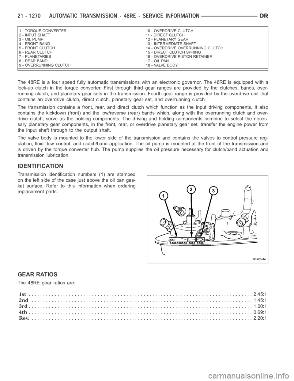
The 48RE is a four speed fully automatic transmissions with an electronic governor. The 48RE is equipped with a
lock-up clutch in the torque converter. First through third gear ranges are provided by the clutches, bands, over-
running clutch, and planetary gear sets in the transmission. Fourth gear range is provided by the overdrive unit that
contains an overdrive clutch, direct clutch, planetary gear set, and overrunning clutch.
The transmission contains a front, rear, and direct clutch which functionas the input driving components. It also
contains the kickdown (front) and the low/reverse (rear) bands which, along with the overrunning clutch and over-
drive clutch, serve as the holding components. The driving and holding components combine to select the neces-
sary planetary gear components, in the front, rear, or overdrive planetary gear set, transfer the engine power from
the input shaft through to the output shaft.
The valve body is mounted to the lower side of the transmission and containsthe valves to control pressure reg-
ulation, fluid flow control, and clutch/band application. The oil pump ismounted at the front of the transmission and
is driven by the torque converter hub. The pump supplies the oil pressure necessary for clutch/band actuation and
transmission lubrication.
IDENTIFICATION
Transmission identification numbers (1) are stamped
on the left side of the case just above the oil pan gas-
ket surface. Refer to this information when ordering
replacement parts.
GEAR RATIOS
The 48RE gear ratios are:
.............................................................................. 2.45:1
............................................................................. 1.45:1
.............................................................................. 1.00:1
.............................................................................. 0.69:1
............................................................................. 2.20:1
1 - TORQUE CONVERTER 10 - OVERDRIVE CLUTCH
2 - INPUT SHAFT 11 - DIRECT CLUTCH
3 - OIL PUMP 12 - PLANETARY GEAR
4 - FRONT BAND 13 - INTERMEDIATE SHAFT
5 - FRONT CLUTCH 14 - OVERDRIVE OVERRUNNING CLUTCH
6 - REAR CLUTCH 15 - DIRECT CLUTCH SPRING
7 - PLANETARIES 16 - OVERDRIVE PISTON RETAINER
8 - REAR BAND 17 - OIL PAN
9 - OVERRUNNING CLUTCH 18 - VALVE BODY
Page 3792 of 5267
OPERATION
The application of each driving or holding component is controlled by the valve body based upon the manual lever
position, throttle pressure, and governor pressure. The governor pressure is a variable pressure input to the valve
body and is one of the signals that a shift is necessary. First through fourth gear are obtained by selectively apply-
ing and releasing the different clutches and bands. Engine power is thereby routed to the various planetary gear
assemblies which combine with the overrunning clutch assemblies to generate the different gear ratios. The torque
converter clutch is hydraulically applied and is released when fluid is vented from the hydraulic circuit by the torque
converter control (TCC) solenoid on the valve body. The torque converter clutch is controlled by the Powertrain
Control Module (PCM). The torque converter clutch engages in fourth gear,and in third gear under various condi-
tions, such as when the O/D switch is OFF, when the vehicle is cruising on a level surface after the vehicle has
warmed up. The torque converter clutch can also be engaged in the MANUAL SECOND gear position if high trans-
mission temperatures are sensed by the PCM. The torque converter clutch will disengage momentarily when an
increase in engine load is sensed by the PCM, such as when the vehicle beginsto go uphill or the throttle pressure
is increased. The torque converter clutch feature increases fuel economyand reduces the transmission fluid tem-
perature.
Since the overdrive clutch is applied in fourth gear only and the direct clutch is applied in all ranges except fourth
gear, the transmission operation for park, neutral, and first through third gear will be described first. Once these
powerflows are described, the third to fourth shift sequence will be described.
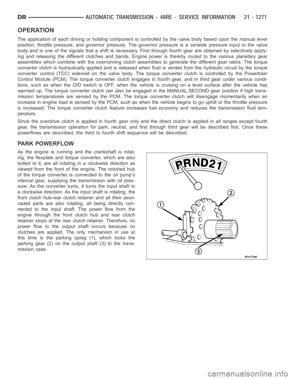
PARK POWERFLOW
As the engine is running and the crankshaft is rotat-
ing, the flexplate and torque converter, which are also
bolted to it, are all rotating in a clockwise direction as
viewed from the front of the engine. The notched hub
of the torque converter is connected to the oil pump’s
internal gear, supplying the transmission with oil pres-
sure. As the converter turns, it turns the input shaft in
a clockwise direction. As the input shaft is rotating, the
front clutch hub-rear clutch retainer and all their asso-
ciated parts are also rotating, all being directly con-
nected to the input shaft. The power flow from the
engine through the front clutch hub and rear clutch
retainer stops at the rear clutch retainer. Therefore, no
power flow to the output shaft occurs because no
clutches are applied. The only mechanism in use at
this time is the parking sprag (1), which locks the
parking gear (2) on the output shaft (3) to the trans-
mission case.
Page 3793 of 5267
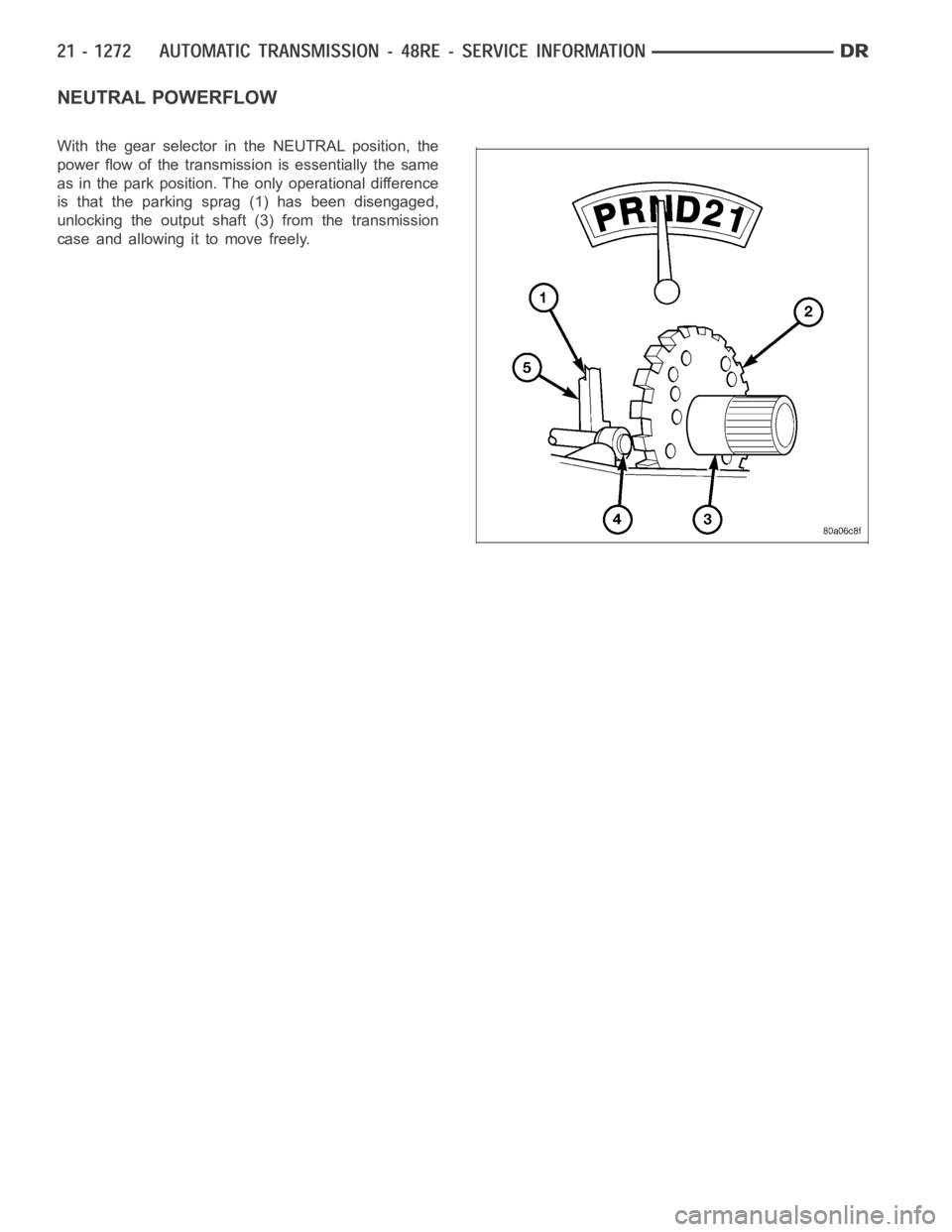
NEUTRAL POWERFLOW
With the gear selector in the NEUTRAL position, the
power flow of the transmission is essentially the same
as in the park position. The only operational difference
is that the parking sprag (1) has been disengaged,
unlocking the output shaft (3) from the transmission
case and allowing it to move freely.
Page 3794 of 5267
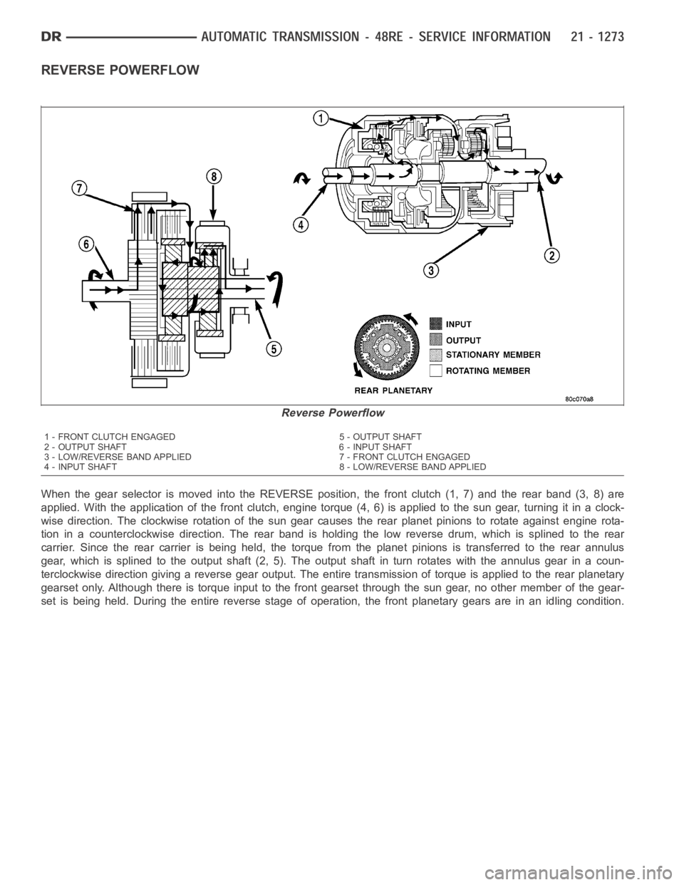
REVERSE POWERFLOW
When the gear selector is moved into the REVERSE position, the front clutch(1, 7) and the rear band (3, 8) are
applied. With the application of the front clutch, engine torque (4, 6) is applied to the sun gear, turning it in a clock-
wise direction. The clockwise rotation of the sun gear causes the rear planet pinions to rotate against engine rota-
tion in a counterclockwise direction. The rear band is holding the low reverse drum, which is splined to the rear
carrier. Since the rear carrier is being held, the torque from the planet pinions is transferred to the rear annulus
gear, which is splined to the output shaft (2, 5). The output shaft in turn rotates with the annulus gear in a coun-
terclockwise direction giving a reverse gear output. The entire transmission of torque is applied to the rear planetary
gearset only. Although there is torque input to the front gearset through the sun gear, no other member of the gear-
set is being held. During the entire reverse stage of operation, the front planetary gears are in an idling condition.
Reverse Powerflow
1 - FRONT CLUTCH ENGAGED 5 - OUTPUT SHAFT
2 - OUTPUT SHAFT 6 - INPUT SHAFT
3 - LOW/REVERSE BAND APPLIED 7 - FRONT CLUTCH ENGAGED
4 - INPUT SHAFT 8 - LOW/REVERSE BAND APPLIED
Page 3795 of 5267
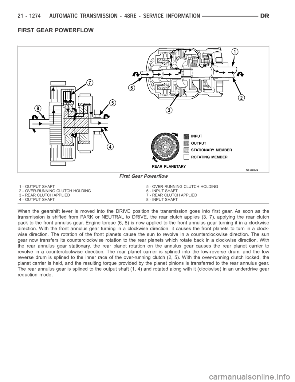
FIRST GEAR POWERFLOW
When the gearshift lever is moved into the DRIVE position the transmissiongoes into first gear. As soon as the
transmission is shifted from PARK or NEUTRAL to DRIVE, the rear clutch applies (3, 7), applying the rear clutch
pack to the front annulus gear. Engine torque (6, 8) is now applied to the front annulus gear turning it in a clockwise
direction. With the front annulus gear turning in a clockwise direction, it causes the front planets to turn in a clock-
wise direction. The rotation of the front planets cause the sun to revolve in a counterclockwise direction. The sun
gear now transfers its counterclockwise rotation to the rear planets which rotate back in a clockwise direction. With
the rear annulus gear stationary, the rear planet rotation on the annulus gear causes the rear planet carrier to
revolve in a counterclockwise direction. The rear planet carrier is splined into the low-reverse drum, and the low
reverse drum is splined to the inner race of the over-running clutch (2, 5).With the over-running clutch locked, the
planet carrier is held, and the resulting torque provided by the planet pinions is transferred to the rear annulus gear.
The rear annulus gear is splined to the output shaft (1, 4) and rotated alongwith it (clockwise) in an underdrive gear
reduction mode.
First Gear Powerflow
1 - OUTPUT SHAFT 5 - OVER-RUNNING CLUTCH HOLDING
2 - OVER-RUNNING CLUTCH HOLDING 6 - INPUT SHAFT
3 - REAR CLUTCH APPLIED 7 - REAR CLUTCH APPLIED
4 - OUTPUT SHAFT 8 - INPUT SHAFT