Page 3858 of 5267
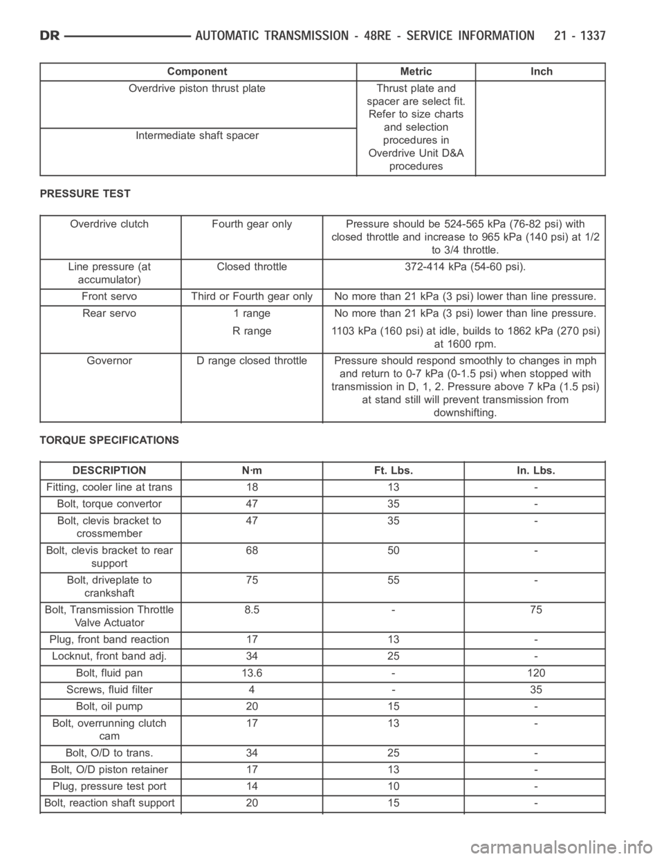
Component Metric Inch
Overdrive piston thrust plate Thrust plate and
spacer are select fit.
Refer to size charts
and selection
procedures in
Overdrive Unit D&A
procedures Intermediateshaft spacer
PRESSURE TEST
Overdrive clutch Fourth gear only Pressure should be 524-565 kPa (76-82 psi) with
closed throttle and increase to 965 kPa (140 psi) at 1/2
to 3/4 throttle.
Line pressure (at
accumulator)Closed throttle 372-414 kPa (54-60 psi).
Front servo Third or Fourth gear only No more than 21 kPa (3 psi) lower than line pressure.
Rearservo 1range Nomorethan21kPa(3psi)lowerthanlinepressure.
R range 1103 kPa (160 psi) at idle, builds to 1862 kPa (270 psi)
at 1600 rpm.
Governor D range closed throttle Pressure should respond smoothly to changes in mph
andreturnto0-7kPa(0-1.5psi)whenstoppedwith
transmission in D, 1, 2. Pressure above 7 kPa (1.5 psi)
at stand still will prevent transmission from
downshifting.
TORQUE SPECIFICATIONS
DESCRIPTION Nꞏm Ft. Lbs. In. Lbs.
Fitting, cooler line at trans 18 13 -
Bolt, torque convertor 47 35 -
Bolt, clevis bracket to
crossmember47 35 -
Bolt, clevis bracket to rear
support68 50 -
Bolt, driveplate to
crankshaft75 55 -
Bolt, Transmission Throttle
Va l v e A c t u a t o r8.5 - 75
Plug, front band reaction 17 13 -
Locknut, front band adj. 34 25 -
Bolt, fluid pan 13.6 - 120
Screws, fluid filter 4 - 35
Bolt, oil pump 20 15 -
Bolt, overrunning clutch
cam17 13 -
Bolt, O/D to trans. 34 25 -
Bolt, O/D piston retainer 17 13 -
Plug, pressure test port 14 10 -
Bolt, reaction shaft support 20 15 -
Page 3859 of 5267
DESCRIPTION Nꞏm Ft. Lbs. In. Lbs.
Locknut, rear band 41 30 -
Bolt, valve body to case 12 - 100
Sensor, trans speed 27 20 -
Screw, solenoid wiring
connector4-35
Screw, solenoid to transfer
plate4-35
Bracket, transmission
range sensor mounting34 25 -
Screw, transmision range
sensor to mounting
bracket5-45
Page 3865 of 5267
ADJUSTMENTS
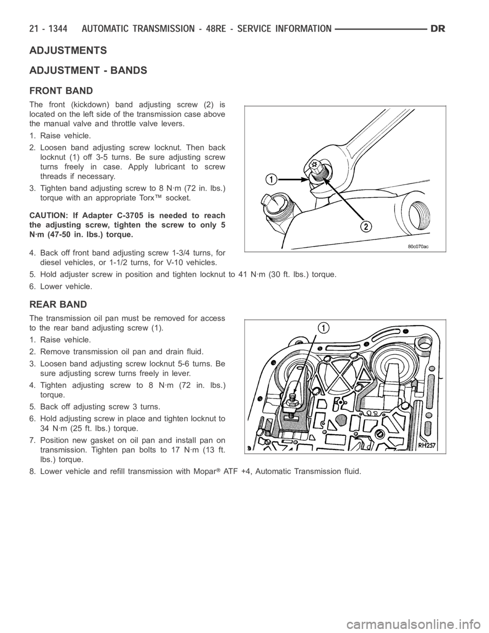
ADJUSTMENT - BANDS
FRONT BAND
The front (kickdown) band adjusting screw (2) is
located on the left side of the transmission case above
the manual valve and throttle valve levers.
1. Raise vehicle.
2. Loosen band adjusting screw locknut. Then back
locknut (1) off 3-5 turns. Be sure adjusting screw
turns freely in case. Apply lubricant to screw
threads if necessary.
3. Tighten band adjusting screw to 8 Nꞏm (72 in. lbs.)
torque with an appropriate Torx™ socket.
CAUTION: If Adapter C-3705 is needed to reach
the adjusting screw, tighten the screw to only 5
Nꞏm (47-50 in. lbs.) torque.
4. Back off front band adjusting screw 1-3/4 turns, for
diesel vehicles, or 1-1/2 turns, for V-10 vehicles.
5. Hold adjuster screw in position and tighten locknut to 41 Nꞏm (30 ft. lbs.) torque.
6. Lower vehicle.
REAR BAND
The transmission oil pan must be removed for access
to the rear band adjusting screw (1).
1. Raise vehicle.
2. Remove transmission oil pan and drain fluid.
3. Loosen band adjusting screw locknut 5-6 turns. Be
sure adjusting screw turns freely in lever.
4. Tighten adjusting screw to 8 Nꞏm (72 in. lbs.)
torque.
5. Back off adjusting screw 3 turns.
6. Hold adjusting screw in place and tighten locknut to
34 Nꞏm (25 ft. lbs.) torque.
7. Position new gasket on oil pan and install pan on
transmission. Tighten pan bolts to 17 Nꞏm (13 ft.
lbs.) torque.
8. Lower vehicle and refill transmission with Mopar
ATF +4, Automatic Transmission fluid.
Page 3866 of 5267
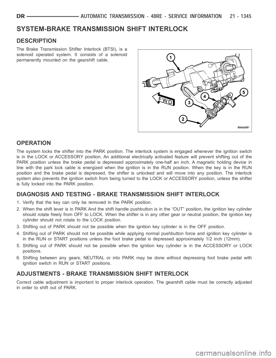
SYSTEM-BRAKE TRANSMISSION SHIFT INTERLOCK
DESCRIPTION
The Brake Transmission Shifter Interlock (BTSI), is a
solenoid operated system. It consists of a solenoid
permanently mounted on the gearshift cable.
OPERATION
The system locks the shifter into the PARK position. The interlock system is engaged whenever the ignition switch
is in the LOCK or ACCESSORY position. An additional electrically activated feature will prevent shifting out of the
PARK position unless the brake pedal is depressed approximately one-halfan inch. A magnetic holding device in
line with the park lock cable is energized when the ignition is in the RUN position. When the key is in the RUN
position and the brake pedal is depressed, the shifter is unlocked and willmove into any position. The interlock
system also prevents the ignition switch from being turned to the LOCK or ACCESSORY position, unless the shifter
is fully locked into the PARK position.
DIAGNOSIS AND TESTING - BRAKE TRANSMISSION SHIFT INTERLOCK
1. Verify that the key can only be removed in the PARK position.
2. When the shift lever is in PARK And the shift handle pushbutton is in the “OUT” position, the ignition key cylinder
should rotate freely from OFF to LOCK. When the shifter is in any other gear or neutral position, the ignition key
cylinder should not rotate to the LOCK position.
3. Shifting out of PARK should not be possible when the ignition key cylinder is in the OFF position.
4. Shifting out of PARK should not be possible while applying normal pushbutton force and ignition key cylinder is
in the RUN or START positions unless the foot brake pedal is depressed approximately 1/2 inch (12mm).
5. Shifting out of PARK should not be possible when the ignition key cylinderisintheACCESSORYorLOCK
positions.
6. Shifting between any gears, NEUTRAL or into PARK may be done without depressing foot brake pedal with
ignition switch in RUN or START positions.
ADJUSTMENTS - BRAKE TRANSMISSION SHIFT INTERLOCK
Correct cable adjustment is important to proper interlock operation. Thegearshift cable must be correctly adjusted
in order to shift out of PARK.
Page 3867 of 5267
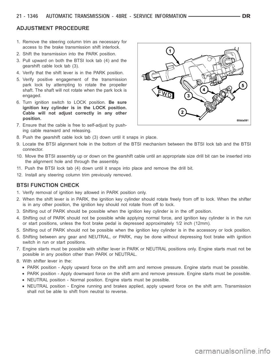
ADJUSTMENT PROCEDURE
1. Remove the steering column trim as necessary for
access to the brake transmission shift interlock.
2. Shift the transmission into the PARK position.
3. Pull upward on both the BTSI lock tab (4) and the
gearshift cable lock tab (3).
4. Verify that the shift lever is in the PARK position.
5. Verify positive engagement of the transmission
park lock by attempting to rotate the propeller
shaft. The shaft will not rotate when the park lock is
engaged.
6. Turn ignition switch to LOCK position.Be sure
ignition key cylinder is in the LOCK position.
Cable will not adjust correctly in any other
position.
7. Ensure that the cable is free to self-adjust by push-
ing cable rearward and releasing.
8. Push the gearshift cable lock tab (3) down until it snaps in place.
9. Locate the BTSI alignment hole in the bottom of the BTSI mechanism betweentheBTSIlocktabandtheBTSI
connector.
10. Move the BTSI assembly up or down on the gearshift cable until an appropriate size drill bit can be inserted into
the alignment hole and through the assembly.
11. Push the BTSI lock tab (4) down until it snaps into place and remove the drill bit.
12. Install any steering column trim previously removed.
BTSI FUNCTION CHECK
1. Verify removal of ignition key allowed in PARK position only.
2. When the shift lever is in PARK, the ignition key cylinder should rotate freely from off to lock. When the shifter
is in any other position, the ignition key should not rotate from off to lock.
3. Shifting out of PARK should be possible when the ignition key cylinder isin the off position.
4. Shifting out of PARK should not be possible while applying normal force,and ignition key cylinder is in the run
or start positions, unless the foot brake pedal is depressed approximately1/2inch(12mm).
5. Shifting out of PARK should not be possible when the ignition key cylinder is in the accessory or lock position.
6. Shifting between any gear and NEUTRAL, or PARK, may be done without depressing foot brake with ignition
switch in run or start positions.
7. Engine starts must be possible with shifter lever in PARK or NEUTRAL positions only. Engine starts must not be
possible in any position other than PARK or NEUTRAL.
8. With shifter lever in the:
PARK position - Apply upward force on the shift arm and remove pressure. Enginestartsmustbepossible.
PARK position - Apply downward force on the shift arm and remove pressure. Engine starts must be possible.
NEUTRAL position - Normal position. Engine starts must be possible.
NEUTRAL position - Engine running and brakes applied, apply upward force on the shift arm. Transmission
shall not be able to shift from neutral to reverse.
Page 3888 of 5267
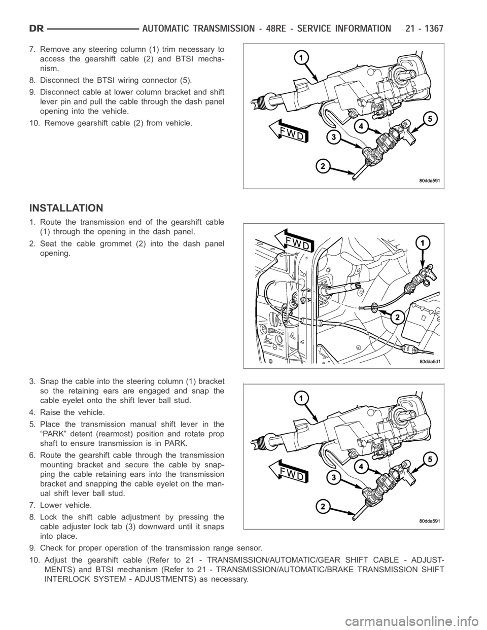
7. Remove any steering column (1) trim necessary to
access the gearshift cable (2) and BTSI mecha-
nism.
8. Disconnect the BTSI wiring connector (5).
9. Disconnect cable at lower column bracket and shift
lever pin and pull the cable through the dash panel
opening into the vehicle.
10. Remove gearshift cable (2) from vehicle.
INSTALLATION
1. Route the transmission end of the gearshift cable
(1) through the opening in the dash panel.
2. Seat the cable grommet (2) into the dash panel
opening.
3. Snap the cable into the steering column (1) bracket
so the retaining ears are engaged and snap the
cable eyelet onto the shift lever ball stud.
4. Raise the vehicle.
5. Place the transmission manual shift lever in the
“PARK” detent (rearmost) position and rotate prop
shaft to ensure transmission is in PARK.
6. Route the gearshift cable through the transmission
mounting bracket and secure the cable by snap-
ping the cable retaining ears into the transmission
bracket and snapping the cable eyelet on the man-
ual shift lever ball stud.
7. Lower vehicle.
8. Lock the shift cable adjustment by pressing the
cable adjuster lock tab (3) downward until it snaps
into place.
9. Check for proper operation of the transmission range sensor.
10. Adjust the gearshift cable (Refer to 21 - TRANSMISSION/AUTOMATIC/GEAR SHIFT CABLE - ADJUST-
MENTS) and BTSI mechanism (Refer to 21 - TRANSMISSION/AUTOMATIC/BRAKE TRANSMISSION SHIFT
INTERLOCK SYSTEM - ADJUSTMENTS) as necessary.
Page 3889 of 5267
ADJUSTMENTS - GEARSHIFT CABLE
Check adjustment by starting the engine in PARK and NEUTRAL. Adjustment isCORRECT if the engine starts only
in these positions. Adjustment is INCORRECT if the engine starts in one butnot both positions. If the engine starts
in any position other than PARK or NEUTRAL, or if the engine will not start atall, the transmission range sensor
may be faulty.
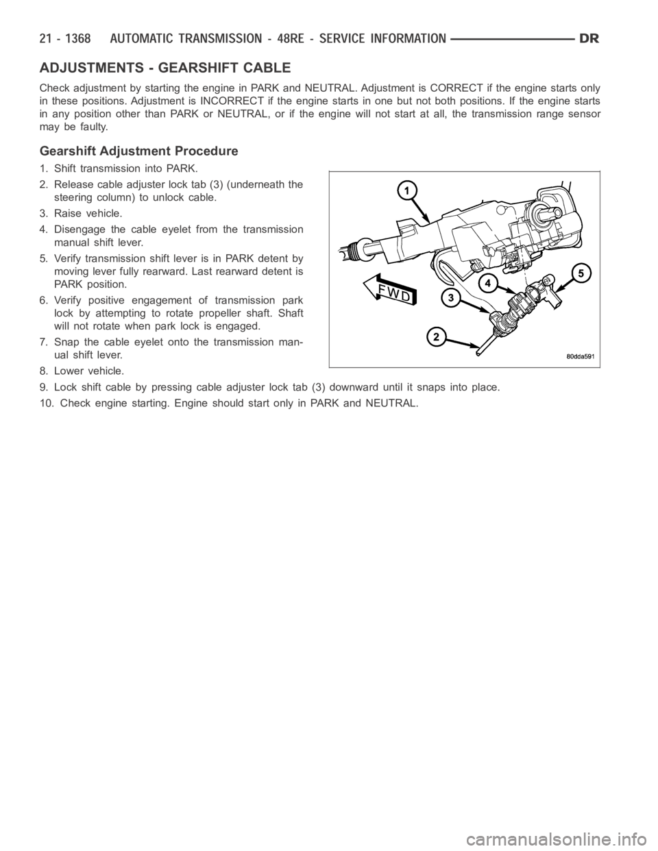
Gearshift Adjustment Procedure
1. Shift transmission into PARK.
2. Release cable adjuster lock tab (3) (underneath the
steering column) to unlock cable.
3. Raise vehicle.
4. Disengage the cable eyelet from the transmission
manual shift lever.
5. Verify transmission shift lever is in PARK detent by
moving lever fully rearward. Last rearward detent is
PARK position.
6. Verify positive engagement of transmission park
lock by attempting to rotate propeller shaft. Shaft
will not rotate when park lock is engaged.
7. Snap the cable eyelet onto the transmission man-
ual shift lever.
8. Lower vehicle.
9. Lock shift cable by pressing cable adjuster lock tab (3) downward until it snaps into place.
10. Check engine starting. Engine should start only in PARK and NEUTRAL.
Page 3891 of 5267
DISASSEMBLY
1. Mark position of support (2) in oil pump body (1)
for assembly alignment reference. Use scriber or
paint to make alignment marks.
2. Place pump body on two wood blocks.
3. Remove reaction shaft support bolts and separate
support (2) from pump body (1).
4. Remove pump inner (3) and outer gears (4).