2006 DODGE RAM SRT-10 lock
[x] Cancel search: lockPage 3921 of 5267
d. Push overdrive piston into position in retainer.
e. Verify that the locating lugs entered the lug bores in the retainer.
6. Install intermediate shaft spacer on intermediate shaft.
7. Install overdrive piston thrust plate on overdrive piston.
8. Install overdrive piston thrust bearing on overdrive piston.
9. Install transmission speed sensorand o-ring seal in overdrive case.
INSTALLATION
1. Be sure overdrive unit Alignment Tool 6227-2 is
fully seated before moving unit. If tool is not seated
and gear splines rotate out of alignment, overdrive
unit will have to be disassembled in order to realign
splines.
2. If overdrive piston retainer was not removed during
service and original case gasket is no longer reus-
able, prepare new gasket by trimming it.
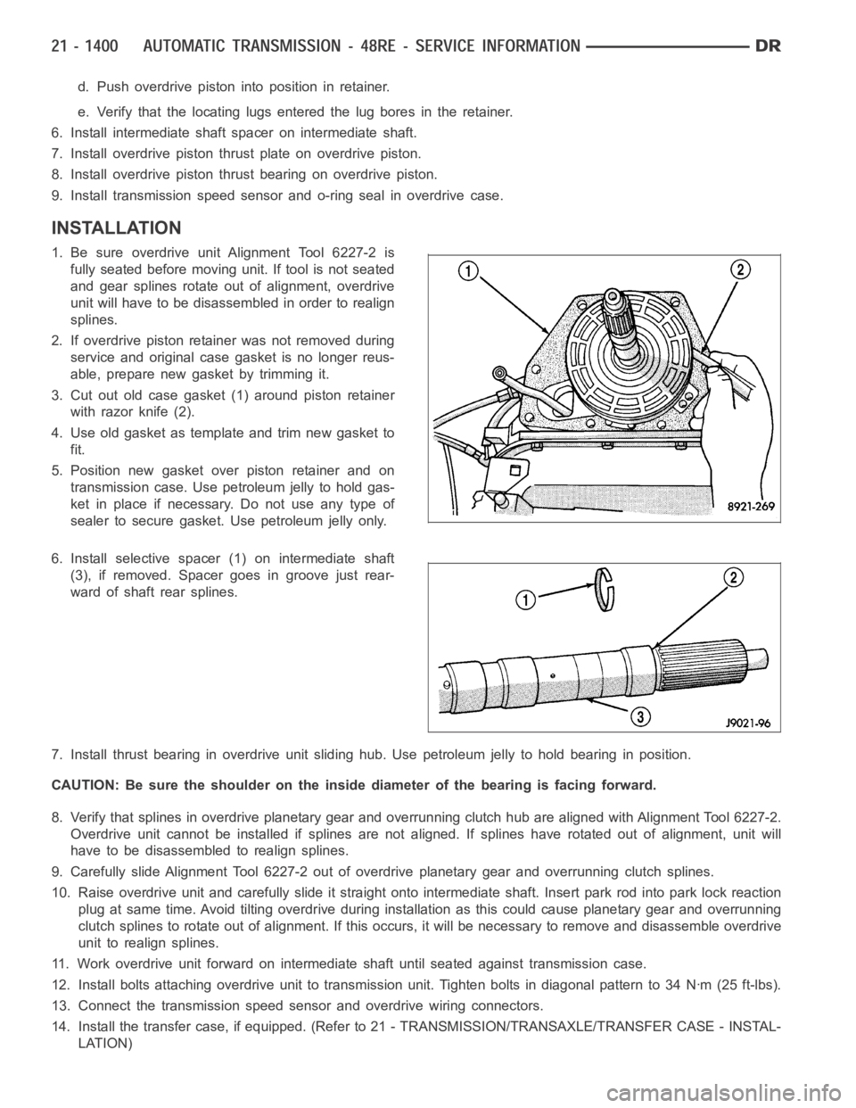
3. Cut out old case gasket (1) around piston retainer
with razor knife (2).
4. Use old gasket as template and trim new gasket to
fit.
5. Position new gasket over piston retainer and on
transmission case. Use petroleum jelly to hold gas-
ket in place if necessary. Do not use any type of
sealer to secure gasket. Use petroleum jelly only.
6. Install selective spacer (1) on intermediate shaft
(3), if removed. Spacer goes in groove just rear-
ward of shaft rear splines.
7. Install thrust bearing in overdrive unit sliding hub. Use petroleum jelly to hold bearing in position.
CAUTION: Be sure the shoulder on the inside diameter of the bearing is facingforward.
8. Verify that splines in overdrive planetary gear and overrunning clutchhub are aligned with Alignment Tool 6227-2.
Overdrive unit cannot be installed if splines are not aligned. If splines have rotated out of alignment, unit will
have to be disassembled to realign splines.
9. Carefully slide Alignment Tool 6227-2 out of overdrive planetary gear and overrunning clutch splines.
10. Raise overdrive unit and carefully slide it straight onto intermediate shaft. Insert park rod into park lock reaction
plug at same time. Avoid tilting overdrive during installation as this could cause planetary gear and overrunning
clutch splines to rotate out of alignment. If this occurs, it will be necessary to remove and disassemble overdrive
unit to realign splines.
11. Work overdrive unit forward on intermediate shaft until seated against transmission case.
12. Install bolts attaching overdrive unit to transmission unit. Tightenbolts in diagonal pattern to 34 Nꞏm (25 ft-lbs).
13. Connect the transmission speed sensor and overdrive wiring connectors.
14. Install the transfer case, if equipped. (Refer to 21 - TRANSMISSION/TRANSAXLE/TRANSFER CASE - INSTAL-
LATION)
Page 3923 of 5267
RETAINER-OVERRUNNING CLUTCH CAM/OVERDRIVE PISTON
DESCRIPTION
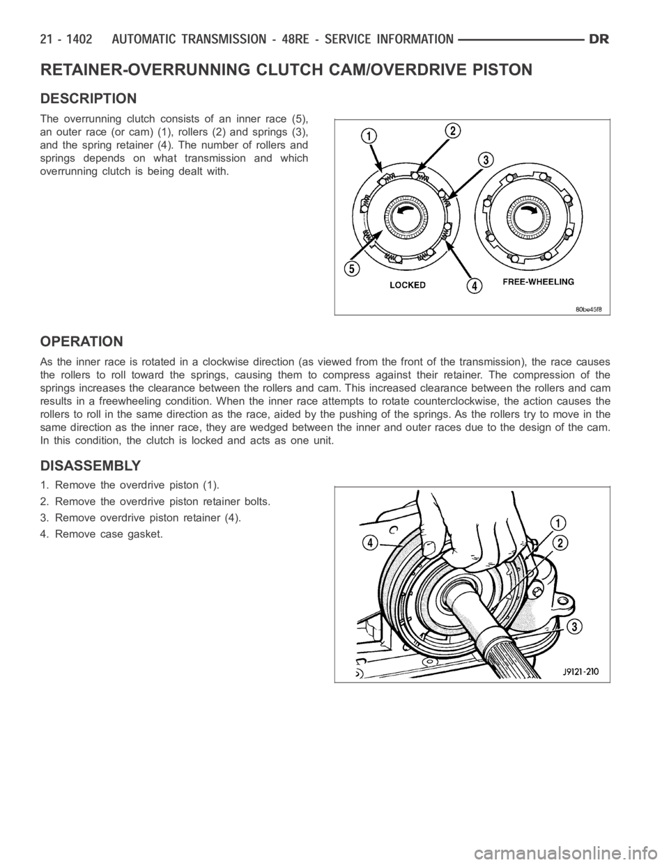
The overrunning clutch consists of an inner race (5),
an outer race (or cam) (1), rollers (2) and springs (3),
and the spring retainer (4). The number of rollers and
springs depends on what transmission and which
overrunning clutch is being dealt with.
OPERATION
Astheinnerraceisrotatedinaclockwisedirection(asviewedfromthefront of the transmission), the race causes
the rollers to roll toward the springs, causing them to compress against their retainer. The compression of the
springs increases the clearance between the rollers and cam. This increased clearance between the rollers and cam
results in a freewheeling condition. When the inner race attempts to rotate counterclockwise, the action causes the
rollers to roll in the same direction as the race, aided by the pushing of thesprings. As the rollers try to move in the
same direction as the inner race, they are wedged between the inner and outer races due to the design of the cam.
In this condition, the clutch is locked and acts as one unit.
DISASSEMBLY
1. Remove the overdrive piston (1).
2. Remove the overdrive piston retainer bolts.
3. Remove overdrive piston retainer (4).
4. Remove case gasket.
Page 3936 of 5267
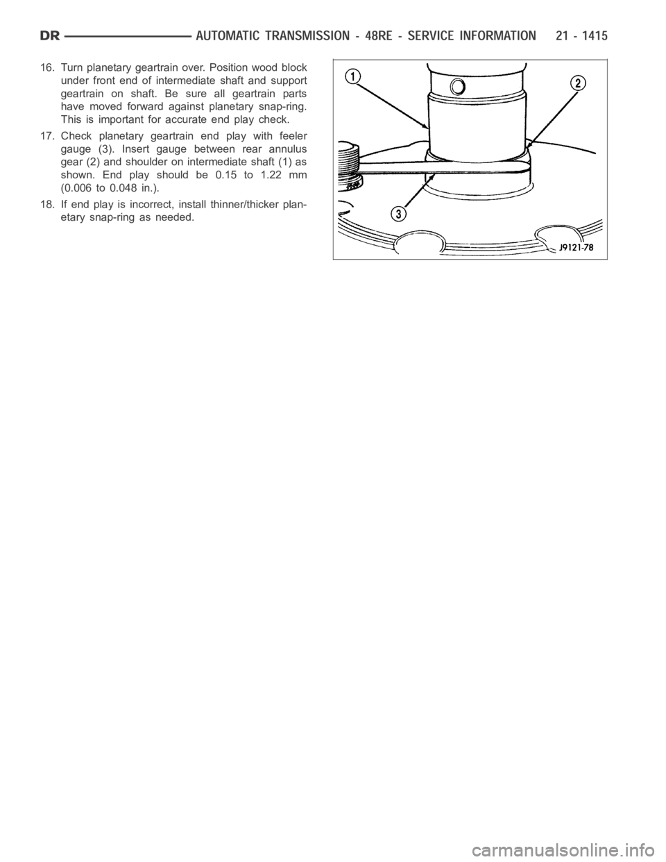
16. Turn planetary geartrain over. Position wood block
under front end of intermediate shaft and support
geartrain on shaft. Be sure all geartrain parts
have moved forward against planetary snap-ring.
This is important for accurate end play check.
17. Check planetary geartrain end play with feeler
gauge (3). Insert gauge between rear annulus
gear (2) and shoulder on intermediate shaft (1) as
shown. End play should be 0.15 to 1.22 mm
(0.006 to 0.048 in.).
18. If end play is incorrect, install thinner/thicker plan-
etary snap-ring as needed.
Page 3938 of 5267
DISASSEMBLY
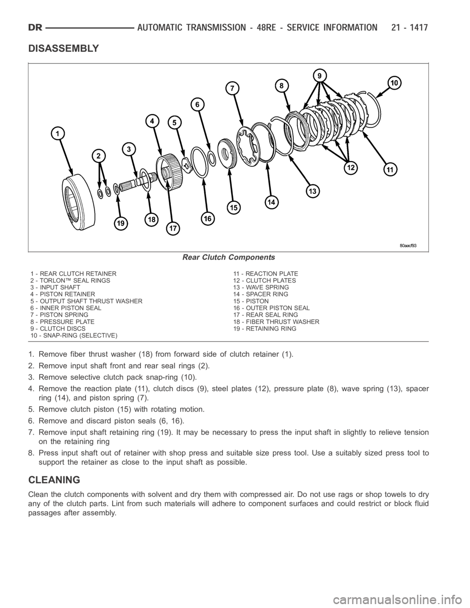
1. Remove fiber thrust washer (18) from forward side of clutch retainer (1).
2. Remove input shaft front and rear seal rings (2).
3. Remove selective clutch pack snap-ring (10).
4. Remove the reaction plate (11), clutch discs (9), steel plates (12), pressure plate (8), wave spring (13), spacer
ring (14), and piston spring (7).
5. Remove clutch piston (15) with rotating motion.
6. Remove and discard piston seals (6, 16).
7. Remove input shaft retaining ring (19). It may be necessary to press the input shaft in slightly to relieve tension
on the retaining ring
8. Press input shaft out of retainer with shop press and suitable size presstool. Use a suitably sized press tool to
support the retainer as close to the input shaft as possible.
CLEANING
Clean the clutch components with solvent and dry them with compressed air.Do not use rags or shop towels to dry
any of the clutch parts. Lint from such materials will adhere to component surfaces and could restrict or block fluid
passages after assembly.
Rear Clutch Components
1 - REAR CLUTCH RETAINER 11 - REACTION PLATE
2 - TORLON™ SEAL RINGS 12 - CLUTCH PLATES
3 - INPUT SHAFT 13 - WAVE SPRING
4 - PISTON RETAINER 14 - SPACER RING
5 - OUTPUT SHAFT THRUST WASHER 15 - PISTON
6 - INNER PISTON SEAL 16 - OUTER PISTON SEAL
7 - PISTON SPRING 17 - REAR SEAL RING
8 - PRESSURE PLATE 18 - FIBER THRUST WASHER
9 - CLUTCH DISCS 19 - RETAINING RING
10 - SNAP-RING (SELECTIVE)
Page 3939 of 5267
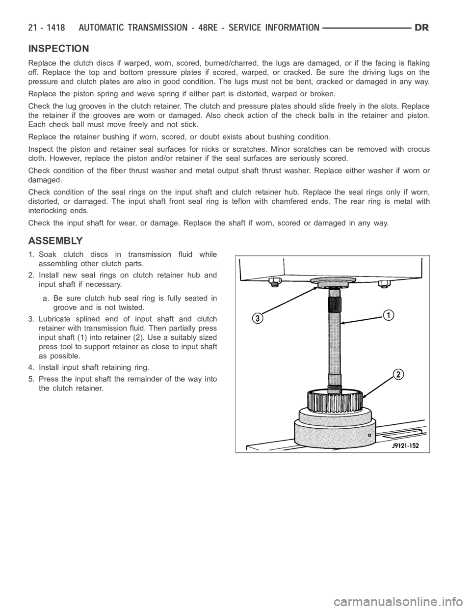
INSPECTION
Replace the clutch discs if warped, worn, scored, burned/charred, the lugs are damaged, or if the facing is flaking
off. Replace the top and bottom pressure plates if scored, warped, or cracked. Be sure the driving lugs on the
pressure and clutch plates are also in good condition. The lugs must not be bent, cracked or damaged in any way.
Replace the piston spring and wave spring if either part is distorted, warped or broken.
Check the lug grooves in the clutch retainer. The clutch and pressure plates should slide freely in the slots. Replace
the retainer if the grooves are worn or damaged. Also check action of the check balls in the retainer and piston.
Each check ball must move freely and not stick.
Replace the retainer bushing if worn, scored, or doubt exists about bushing condition.
Inspect the piston and retainer seal surfaces for nicks or scratches. Minor scratches can be removed with crocus
cloth. However, replace the piston and/or retainer if the seal surfaces are seriously scored.
Check condition of the fiber thrust washer and metal output shaft thrust washer. Replace either washer if worn or
damaged.
Check condition of the seal rings on the input shaft and clutch retainer hub. Replace the seal rings only if worn,
distorted, or damaged. The input shaft front seal ring is teflon with chamfered ends. The rear ring is metal with
interlocking ends.
Check the input shaft for wear, or damage. Replace the shaft if worn, scoredor damaged in any way.
ASSEMBLY
1. Soak clutch discs in transmission fluid while
assembling other clutch parts.
2. Install new seal rings on clutch retainer hub and
input shaft if necessary.
a. Be sure clutch hub seal ring is fully seated in
groove and is not twisted.
3. Lubricate splined end of input shaft and clutch
retainer with transmission fluid. Then partially press
input shaft (1) into retainer (2). Use a suitably sized
press tool to support retainer as close to input shaft
as possible.
4. Install input shaft retaining ring.
5. Press the input shaft the remainder of the way into
the clutch retainer.
Page 3945 of 5267
ACTUATOR-THROTTLE VALVE
DESCRIPTION
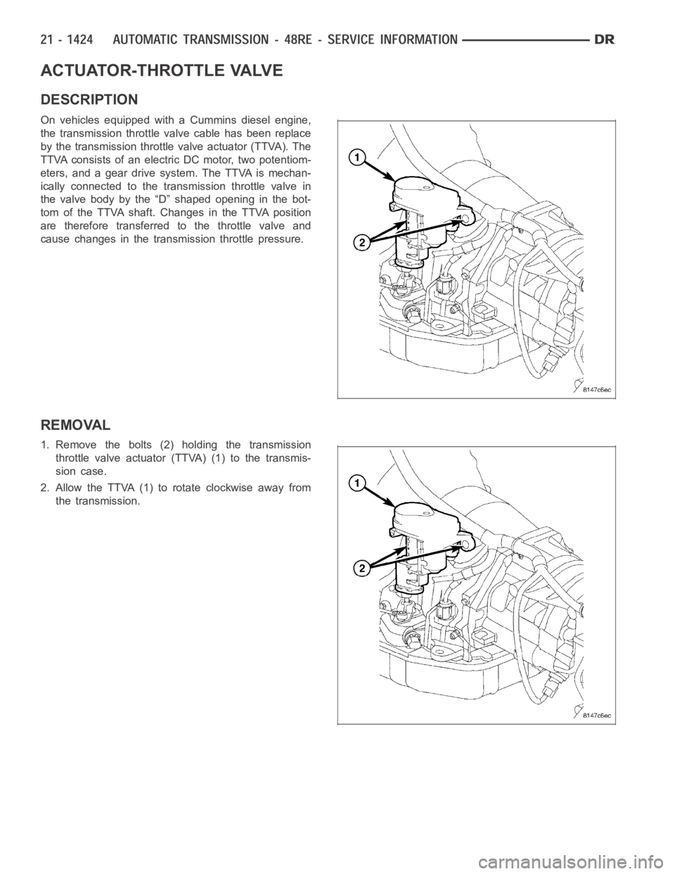
On vehicles equipped with a Cummins diesel engine,
the transmission throttle valve cable has been replace
by the transmission throttle valve actuator (TTVA). The
TTVA consists of an electric DC motor, two potentiom-
eters, and a gear drive system. The TTVA is mechan-
ically connected to the transmission throttle valve in
the valve body by the “D” shaped opening in the bot-
tom of the TTVA shaft. Changes in the TTVA position
are therefore transferred to the throttle valve and
cause changes in the transmission throttle pressure.
REMOVAL
1. Remove the bolts (2) holding the transmission
throttle valve actuator (TTVA) (1) to the transmis-
sion case.
2. Allow the TTVA (1) to rotate clockwise away from
the transmission.
Page 3948 of 5267
CABLE-THROTTLE VALVE
DESCRIPTION
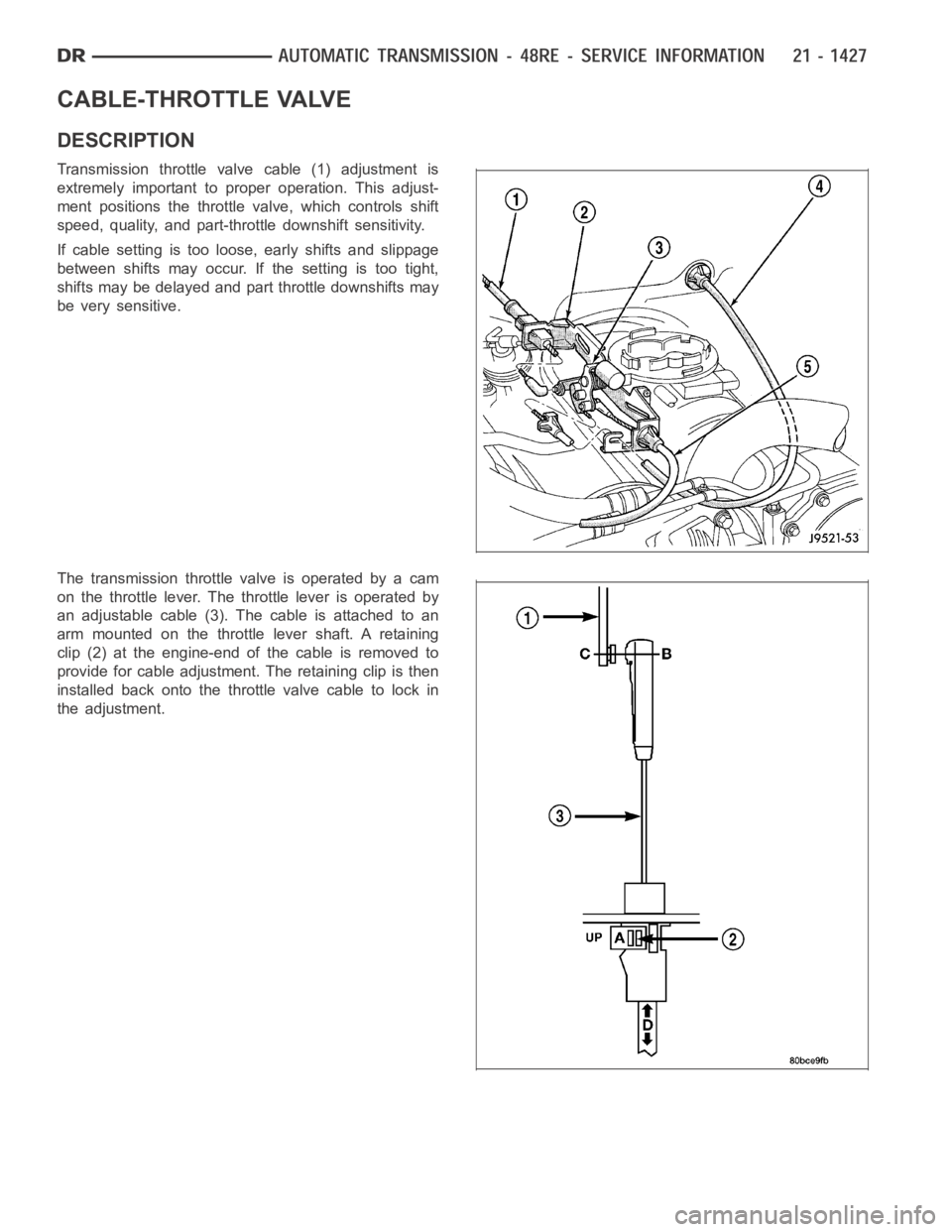
Transmission throttle valve cable (1) adjustment is
extremely important to proper operation. This adjust-
ment positions the throttle valve, which controls shift
speed, quality, and part-throttle downshift sensitivity.
If cable setting is too loose, early shifts and slippage
between shifts may occur. If the setting is too tight,
shifts may be delayed and part throttle downshifts may
be very sensitive.
The transmission throttlevalveisoperatedbyacam
on the throttle lever. The throttle lever is operated by
an adjustable cable (3). The cable is attached to an
arm mounted on the throttle lever shaft. A retaining
clip (2) at the engine-end of the cable is removed to
provide for cable adjustment. The retaining clip is then
installedbackontothethrottlevalvecabletolockin
the adjustment.
Page 3950 of 5267
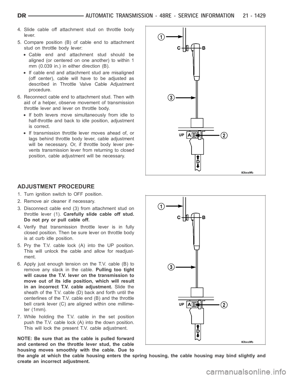
4. Slide cable off attachment stud on throttle body
lever.
5. Compare position (B) of cable end to attachment
stud on throttle body lever:
Cable end and attachment stud should be
aligned (or centered on one another) to within 1
mm (0.039 in.) in either direction (B).
If cable end and attachment stud are misaligned
(off center), cable will have to be adjusted as
described in Throttle Valve Cable Adjustment
procedure.
6. Reconnect cable end to attachment stud. Then with
aid of a helper, observe movement of transmission
throttle lever and lever on throttle body.
If both levers move simultaneously from idle to
half-throttle and back to idle position, adjustment
is correct.
If transmission throttle lever moves ahead of, or
lags behind throttle body lever, cable adjustment
will be necessary. Or, if throttle body lever pre-
vents transmission lever from returning to closed
position, cable adjustment will be necessary.
ADJUSTMENT PROCEDURE
1. Turn ignition switch to OFF position.
2. Remove air cleaner if necessary.
3. Disconnect cable end (3) from attachment stud on
throttle lever (1).Carefully slide cable off stud.
Do not pry or pull cable off.
4. Verify that transmission throttle lever is in fully
closed position. Then be sure lever on throttle body
is at curb idle position.
5. Pry the T.V. cable lock (A) into the UP position.
This will unlock the cable and allow for readjust-
ment.
6. Apply just enough tension on the T.V. cable (B) to
remove any slack in the cable.Pulling too tight
will cause the T.V. lever on the transmission to
move out of its idle position, which will result
in an incorrect T.V. cable adjustment.Slide the
sheath of the T.V. cable (D) back and forth until the
centerlines of the T.V. cable end (B) and the throttle
bell crank lever (C) are aligned within one millime-
ter (1mm).
7. While holding the T.V. cable in the set position
push the T.V. cable lock (A) into the down position.
This will lock the present T.V. cable adjustment.
NOTE:Besurethatasthecableispulledforward
and centered on the throttle lever stud, the cable
housing moves smoothly with the cable. Due to
the angle at which the cable housing enters the spring housing, the cable housing may bind slightly and
create an incorrect adjustment.