2006 DODGE RAM SRT-10 lock
[x] Cancel search: lockPage 3954 of 5267
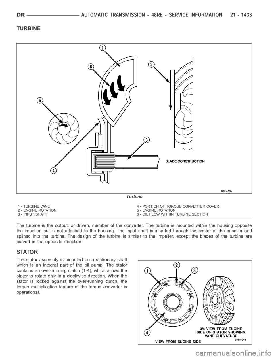
TURBINE
The turbine is the output, or driven, member of the converter. The turbine is mounted within the housing opposite
the impeller, but is not attached to the housing. The input shaft is inserted through the center of the impeller and
splined into the turbine. The design of the turbine is similar to the impeller, except the blades of the turbine are
curved in the opposite direction.
STATOR
The stator assembly is mounted on a stationary shaft
which is an integral part of the oil pump. The stator
contains an over-running clutch (1-4), which allows the
stator to rotate only in a clockwise direction. When the
stator is locked against theover-runningclutch,the
torque multiplication feature of the torque converter is
operational.
Turbine
1 - TURBINE VANE 4 - PORTION OF TORQUE CONVERTER COVER
2 - ENGINE ROTATION 5 - ENGINE ROTATION
3 - INPUT SHAFT 6 - OIL FLOW WITHIN TURBINE SECTION
Page 3955 of 5267
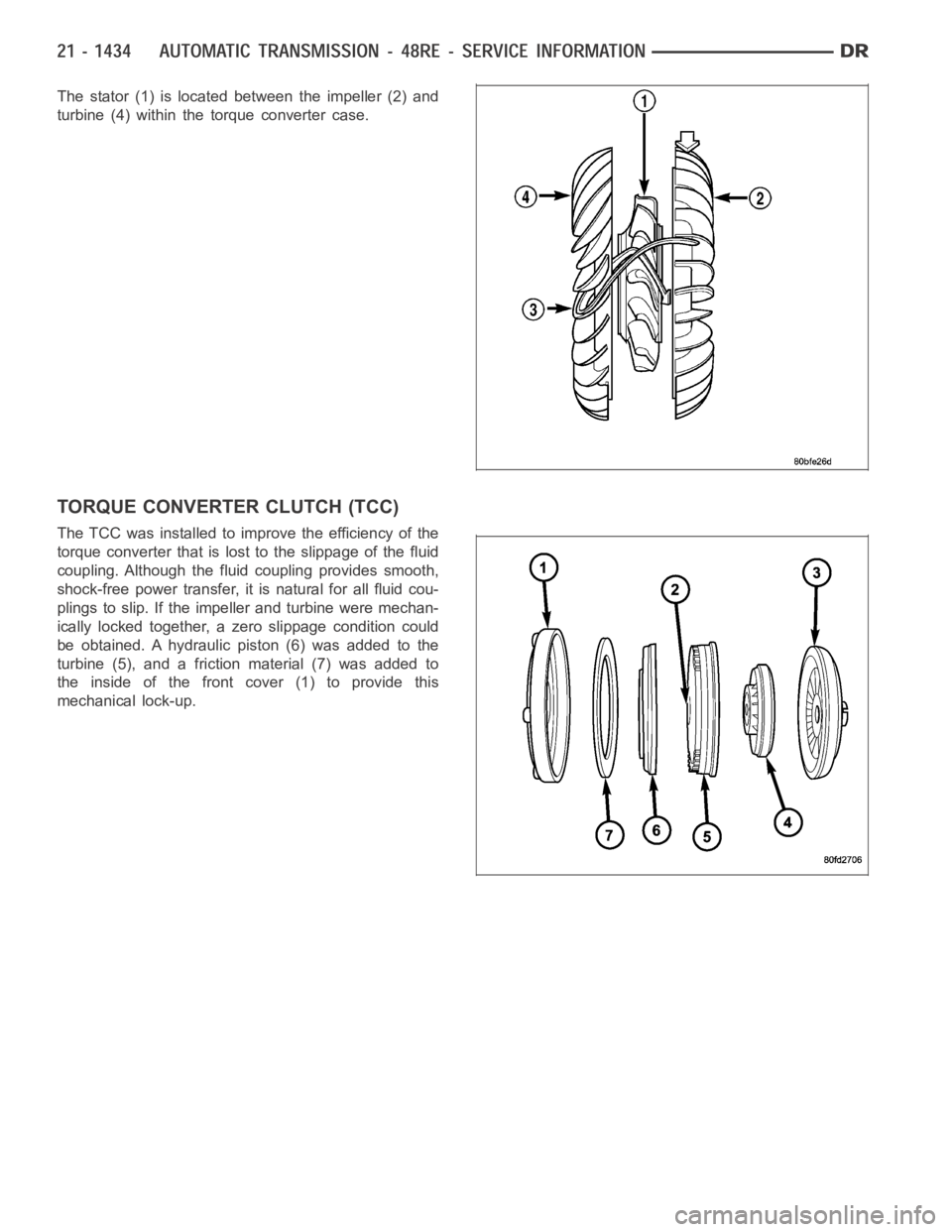
The stator (1) is located between the impeller (2) and
turbine (4) within the torque converter case.
TORQUE CONVERTER CLUTCH (TCC)
The TCC was installed to improve the efficiency of the
torque converter that is lost to the slippage of the fluid
coupling. Although the fluid coupling provides smooth,
shock-free power transfer, it is natural for all fluid cou-
plings to slip. If the impeller and turbine were mechan-
ically locked together, a zero slippage condition could
be obtained. A hydraulic piston (6) was added to the
turbine (5), and a friction material (7) was added to
the inside of the front cover (1) to provide this
mechanical lock-up.
Page 3956 of 5267
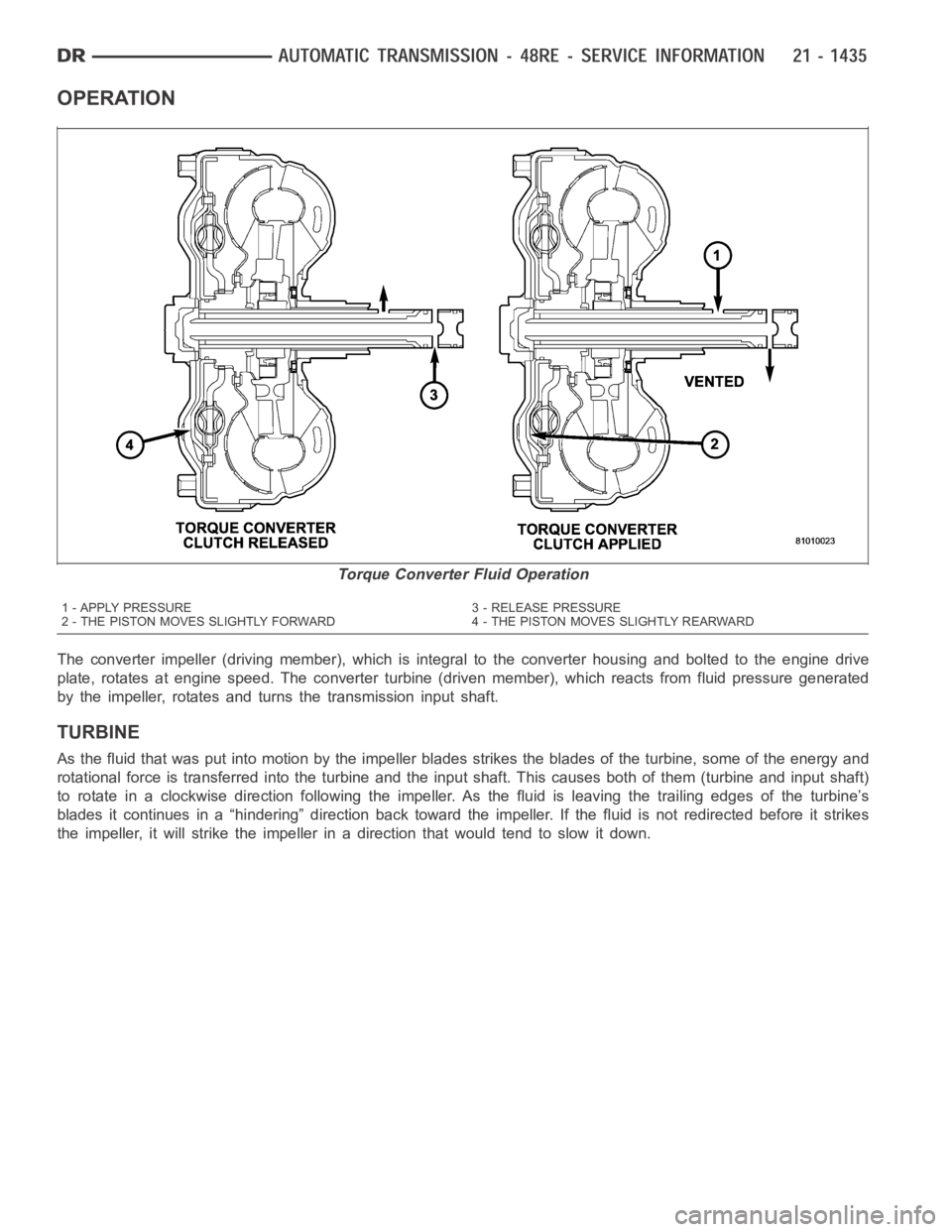
OPERATION
The converter impeller (driving member), which is integral to the converter housing and bolted to the engine drive
plate, rotates at engine speed. The converter turbine (driven member), which reacts from fluid pressure generated
by the impeller, rotates and turns the transmission input shaft.
TURBINE
As the fluid that was put into motion bythe impeller blades strikes the blades of the turbine, some of the energy and
rotational force is transferred into the turbine and the input shaft. Thiscauses both of them (turbine and input shaft)
to rotate in a clockwise direction following the impeller. As the fluid is leaving the trailing edges of the turbine’s
blades it continues in a “hindering” direction back toward the impeller. If the fluid is not redirected before it strikes
the impeller, it will strike the impeller in a direction that would tend to slow it down.
Torque Converter Fluid Operation
1 - APPLY PRESSURE 3 - RELEASE PRESSURE
2 - THE PISTON MOVES SLIGHTLY FORWARD 4 - THE PISTON MOVES SLIGHTLY REARWARD
Page 3957 of 5267
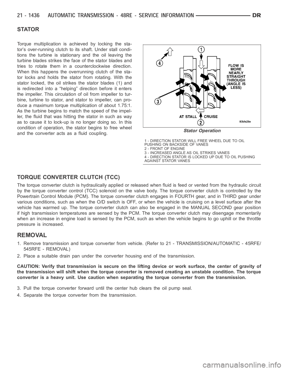
STATOR
Torque multiplication is achieved by locking the sta-
tor’s over-running clutch to its shaft. Under stall condi-
tions the turbine is stationary and the oil leaving the
turbine blades strikes the face of the stator blades and
tries to rotate them in a counterclockwise direction.
When this happens the overrunning clutch of the sta-
tor locks and holds the stator from rotating. With the
stator locked, the oil strikes the stator blades (1) and
is redirected into a “helping” direction before it enters
the impeller. This circulation of oil from impeller to tur-
bine, turbine to stator, and stator to impeller, can pro-
duce a maximum torque multiplication of about 1.75:1.
As the turbine begins to match the speed of the impel-
ler, the fluid that was hitting the stator in such as way
as to cause it to lock-up is no longer doing so. In this
condition of operation, the stator begins to free wheel
and the converter acts as a fluid coupling.
TORQUE CONVERTER CLUTCH (TCC)
The torque converter clutch is hydraulically applied or released when fluid is feed or vented from the hydraulic circuit
by the torque converter control (TCC) solenoid on the valve body. The torque converter clutch is controlled by the
Powertrain Control Module (PCM). The torque converter clutch engages in FOURTH gear, and in THIRD gear under
various conditions, such as when the O/D switch is OFF, or when the vehicle is cruising on a level surface after the
vehicle has warmed up. The torque converter clutch can also be engaged in the MANUAL SECOND gear position
if high transmission temperatures are sensed by the PCM. The torque converter clutch may disengage momentarily
when an increase in engine load is sensed by the PCM, such as when the vehiclebegins to go uphill or the throttle
pressure is increased.
REMOVAL
1. Remove transmission and torque converter from vehicle. (Refer to 21 - TRANSMISSION/AUTOMATIC - 45RFE/
545RFE - REMOVAL)
2. Place a suitable drain pan under the converter housing end of the transmission.
CAUTION: Verify that transmission is secure on the lifting device or work surface, the center of gravity of
the transmission will shift when the torque converter is removed creatingan unstable condition. The torque
converter is a heavy unit. Use caution when separating the torque converter from the transmission.
3. Pull the torque converter forward until the center hub clears the oil pumpseal.
4. Separate the torque converter from the transmission.
Stator Operation
1 - DIRECTION STATOR WILL FREE WHEEL DUE TO OIL
PUSHING ON BACKSIDE OF VANES
2-FRONTOFENGINE
3 - INCREASED ANGLE AS OIL STRIKES VANES
4 - DIRECTION STATOR IS LOCKED UP DUE TO OIL PUSHING
AGAINST STATOR VANES
Page 3959 of 5267
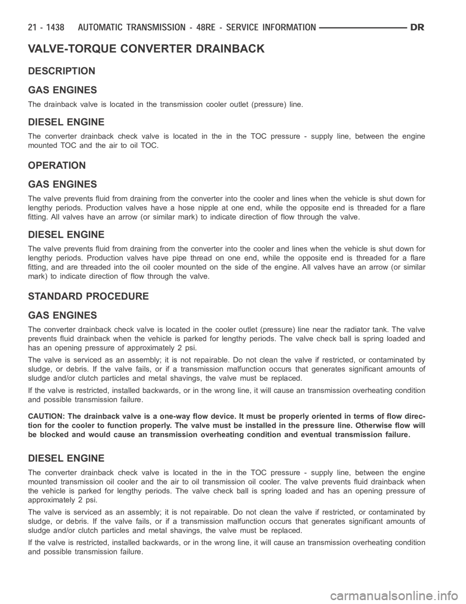
VALVE-TORQUE CONVERTER DRAINBACK
DESCRIPTION
GAS ENGINES
The drainback valve is located in the transmission cooler outlet (pressure) line.
DIESEL ENGINE
The converter drainback check valve is located in the in the TOC pressure - supply line, between the engine
mounted TOC and the air to oil TOC.
OPERATION
GAS ENGINES
The valve prevents fluid from draining from the converter into the cooler and lines when the vehicle is shut down for
lengthy periods. Production valves have a hose nipple at one end, while theopposite end is threaded for a flare
fitting. All valves have an arrow (or similar mark) to indicate direction of flow through the valve.
DIESEL ENGINE
The valve prevents fluid from draining from the converter into the cooler and lines when the vehicle is shut down for
lengthy periods. Production valves have pipe thread on one end, while the opposite end is threaded for a flare
fitting, and are threaded into the oil cooler mounted on the side of the engine. All valves have an arrow (or similar
mark) to indicate direction of flow through the valve.
STANDARD PROCEDURE
GAS ENGINES
The converter drainback check valve is located in the cooler outlet (pressure) line near the radiator tank. The valve
prevents fluid drainback when the vehicle is parked for lengthy periods. The valve check ball is spring loaded and
has an opening pressure of approximately 2 psi.
The valve is serviced as an assembly; it is not repairable. Do not clean the valve if restricted, or contaminated by
sludge, or debris. If the valve fails, or if a transmission malfunction occurs that generates significant amounts of
sludge and/or clutch particles and metal shavings, the valve must be replaced.
If the valve is restricted, installed backwards, or in the wrong line, it will cause an transmission overheating condition
and possible transmission failure.
CAUTION: The drainback valve is a one-way flow device. It must be properly orientedintermsofflowdirec-
tion for the cooler to function properly. The valve must be installed in thepressure line. Otherwise flow will
be blocked and would cause an transmission overheating condition and eventual transmission failure.
DIESEL ENGINE
The converter drainback check valve is located in the in the TOC pressure - supply line, between the engine
mounted transmission oil cooler and the air to oil transmission oil cooler. The valve prevents fluid drainback when
the vehicle is parked for lengthy periods. The valve check ball is spring loaded and has an opening pressure of
approximately 2 psi.
The valve is serviced as an assembly; it is not repairable. Do not clean the valve if restricted, or contaminated by
sludge, or debris. If the valve fails, or if a transmission malfunction occurs that generates significant amounts of
sludge and/or clutch particles and metal shavings, the valve must be replaced.
If the valve is restricted, installed backwards, or in the wrong line, it will cause an transmission overheating condition
and possible transmission failure.
Page 3960 of 5267
CAUTION: The drainback valve is a one-way flow device. It must be properly orientedintermsofflowdirec-
tion for the cooler to function properly. The valve must be installed in thepressure line. Otherwise flow will
be blocked and would cause an transmissionn overheating condition and eventual transmission failure.
Page 3964 of 5267
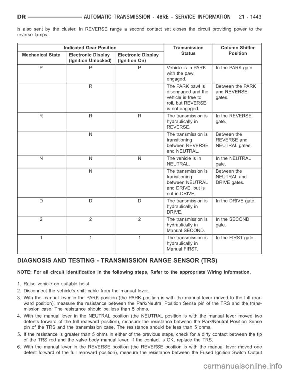
is also sent by the cluster. In REVERSE range a second contact set closes thecircuit providing power to the
reverse lamps.
Indicated Gear Position Transmission
StatusColumn Shifter
Position
Mechanical State Electronic Display
(Ignition Unlocked)Electronic Display
(Ignition On)
P P P Vehicle is in PARK
with the pawl
engaged.In the PARK gate.
R The PARK pawl is
disengaged and the
vehicle is free to
roll, but REVERSE
is not engaged.Between the PARK
and REVERSE
gates.
R R R The transmission is
hydraulically in
REVERSE.In the REVERSE
gate.
N The transmission is
transitioning
between REVERSE
and NEUTRAL.Between the
REVERSE and
NEUTRAL gates.
N N N The vehicle is in
NEUTRAL.In the NEUTRAL
gate.
N The transmission is
transitioning
between NEUTRAL
and DRIVE, but is
not in DRIVE.Between the
NEUTRAL and
DRIVE gates.
D D D The transmission is
hydraulically in
DRIVE.In the DRIVE gate,
2 2 2 The transmission is
hydraulically in
Manual SECOND.In the SECOND
gate.
1 1 1 The transmission is
hydraulically in
Manual FIRST.In the FIRST gate.
DIAGNOSIS AND TESTING - TRANSMISSION RANGE SENSOR (TRS)
NOTE: For all circuit identification in the following steps, Refer to the appropriate Wiring Information.
1. Raise vehicle on suitable hoist.
2. Disconnect the vehicle’s shift cable from the manual lever.
3. With the manual lever in the PARK position (the PARK position is with the manual lever moved to the full rear-
ward position), measure the resistance between the Park/Neutral PositionSensepinoftheTRSandthetrans-
mission case. The resistance should be less than 5 ohms.
4. With the manual lever in the NEUTRAL position (the NEUTRAL position is with the manual lever moved two
detents forward of the full rearward position), measure the resistance between the Park/Neutral Position Sense
pin of the TRS and the transmission case. The resistance should be less than5ohms.
5. If the resistance is greater than 5 ohms in either of the previous steps, check for a dirty contact between the tip
of the TRS rod and the valve body manual lever. If the contact is OK, replace the TRS.
6. With the manual lever in the REVERSE position (the REVERSE position is with the manual lever moved one
detent forward of the full rearward position), measure the resistance between the Fused Ignition Switch Output
Page 3972 of 5267
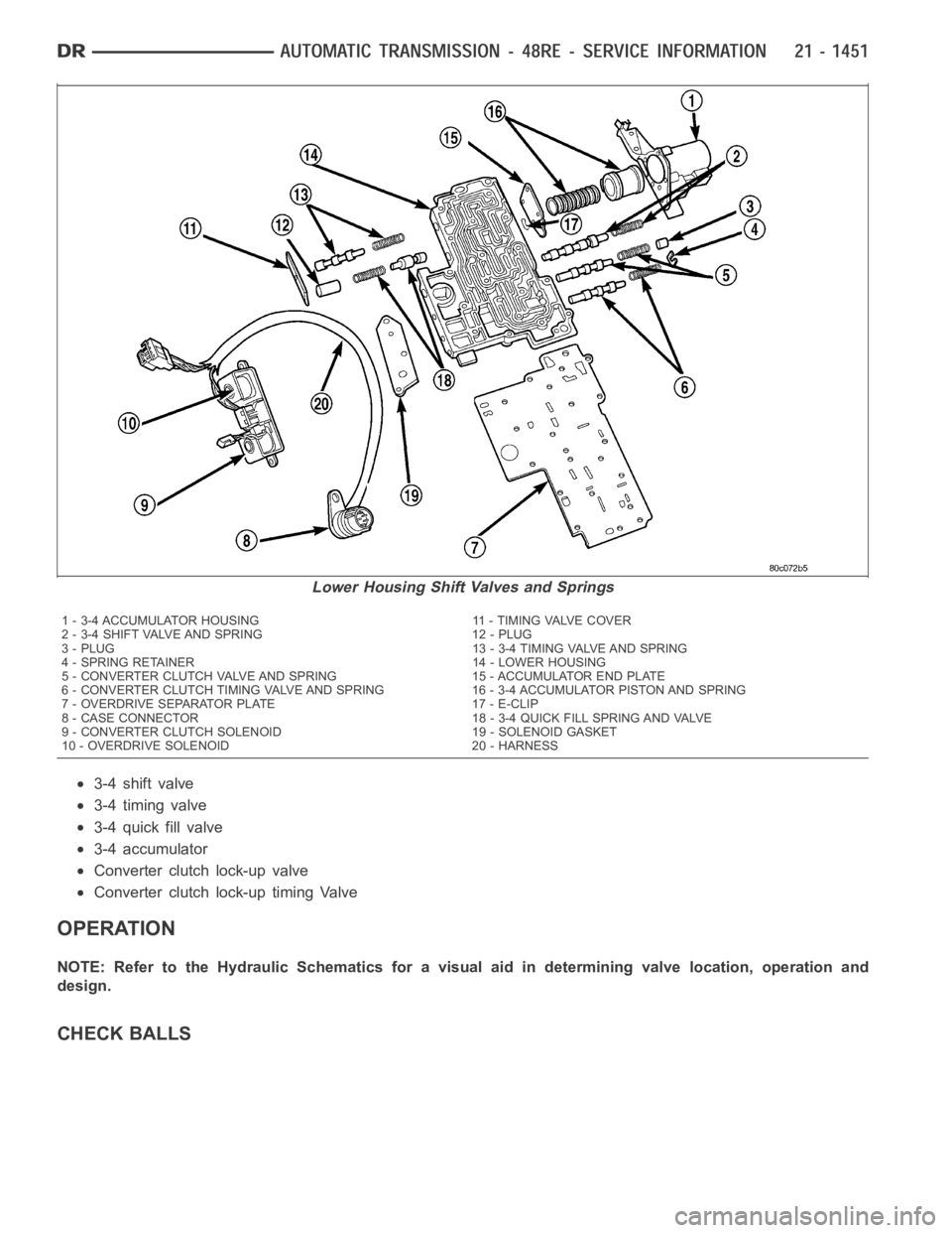
3-4 shift valve
3-4 timing valve
3-4 quick fill valve
3-4 accumulator
Converter clutch lock-up valve
Converter clutch lock-up timing Valve
OPERATION
NOTE: Refer to the Hydraulic Schematics for a visual aid in determining valve location, operation and
design.
CHECK BALLS
Lower Housing Shift Valves and Springs
1 - 3-4 ACCUMULATOR HOUSING 11 - TIMING VALVE COVER
2 - 3-4 SHIFT VALVE AND SPRING 12 - PLUG
3 - PLUG 13 - 3-4 TIMING VALVE AND SPRING
4 - SPRING RETAINER 14 - LOWER HOUSING
5 - CONVERTER CLUTCH VALVE AND SPRING 15 - ACCUMULATOR END PLATE
6 - CONVERTER CLUTCH TIMING VALVE AND SPRING 16 - 3-4 ACCUMULATOR PISTON ANDSPRING
7 - OVERDRIVE SEPARATOR PLATE 17 - E-CLIP
8 - CASE CONNECTOR 18 - 3-4 QUICK FILL SPRING AND VALVE
9 - CONVERTER CLUTCH SOLENOID 19 - SOLENOID GASKET
10 - OVERDRIVE SOLENOID 20 - HARNESS