Page 498 of 5135

AVENSIS REPAIR MANUAL (RM1018E)
2 PERFORM ACTIVE TEST BY HAND±HELD TESTER(OPERATE OCV)
(a) Connect the hand±held tester to the DLC3.
(b) Start the engi")
05±326
± DIAGNOSTICSSFI SYSTEM (1AZ±FSE)
AVENSIS REPAIR MANUAL (RM1018E)
2 PERFORM ACTIVE TEST BY HAND±HELD TESTER(OPERATE OCV)
(a) Connect the hand±held tester to the DLC3.
(b) Start the engine and warm it up.
(c) Turn the ignition switch ON and push the hand±held tester main switch ON.
(d) Select the item ºDIAGNOSIS / OBD/MOBD / ACTIVE TEST / VVT CTRL B1º.
(e) Check the engine speed when operating the OCV by the hand±held tester.
Standard:
Tester operationSpecified condition
OCV is OFFNormal engine speed
OCV is ONRough idle or engine stall
NG Go to step 4
OK
3 CHECK IF DTC OUTPUTS REOCCUR
(a) Clear the DTC.
(1) Operating the hand±held tester to erase the codes, or disconnecting the battery terminal or the
EFI and ETCS fuses for 60 seconds or more.
(b) Start the engine and warm it up.
(c) Drive the vehicle around for 10 minutes or more.
(d) Read output DTC using the hand±held tester.
Standard: No DTC output.
HINT:
*: DTCs P0011 or P0012 is output when a foreign object in engine oil is caught in some part of the system.
These codes will stay registered even if the system returns to normal after a short time. These foreign objects
are then captured by the oil filter, thus eliminating the source of the problem.
OK VVT SYSTEM OK *
NG
Page 500 of 5135
05±328
±
DIAGNOSTICS SFI SYSTEM(1AZ±FSE)
AVENSIS REPAIR MANUAL (RM1018E)
9REPLACE CAMSHAFT TIMING GEAR ASSY (See page 14±240)
GO
10CHECK BLOCKAGE(OCV, OIL CHECK VALVE AND OIL HOLE)
NGREPAIR OR REPLACE
OK
11CHECK IF DTC OUTPUTS REOCCUR
(a)Clear the DTC. (1)Operating the hand±held tester to erase the codes, or disconnecting the batter\
y terminal or the
EFI and ETCS fuses for 60 seconds or more.
(b)Start the engine and warm it up.
(c)Drive the vehicle around for 10 minutes or more.
(d)Read output DTC using the hand±held tester.
Standard: No DTC output.
HINT:
*: DTCs P0011 or P0012 is output when a foreign object in engine oil is caught in so\
me part of the system.
These codes will stay registered even if the system returns to normal after a\
short time. These foreign objects
are then captured by the oil filter, thus eliminating the source of the problem.
OKVVT SYSTEM OK
NG
CHECK AND REPLACE ECM (See page 01±32)
Page 539 of 5135

Heated Oxy")
A76821
Wire Harness Side
B1S1B2S1 H7 H9
Heated Oxygen Sensor Connector OX
HT
OX
HT
E1E1
A76823
OX2A
ECM Connector E12
OX1A
HT2A HT1A
E2 E13
A72920
Reference (Bank 1 Sensor 1 System Drawing)
Heated Oxygen Sensor
EFI Relay
Heater
Sensor
OX1A HT1A
Duty
Control ECM
From
Battery
EFI Fuse
E2 EFI No. 2
Fuse
MREL OX HT
E1 +B
05±404
± DIAGNOSTICSSFI SYSTEM (1AZ±FSE)
AVENSIS REPAIR MANUAL (RM1018E)
23 CHECK HARNESS AND CONNECTOR(HEATED OXYGEN SENSOR ± ECM)
(a) Disconnect the H7 or H9 heated oxygen sensor connec-
tor.
(b) Disconnect the E12 and E13 ECM connectors.
(c) Check for continuity between the wire harness side con-
nectors.
Standard (Check for open):
Symbols (Terminal No.)Specified condition
OX (H7±3) ± OX1A (E12±22)
HT (H7±1) ± HT1A (E12±5)
E1 (H7±4) ± E2 (E13±28)ContinuityOX (H8±3) ± OX2A (E12±23)Continuity
HT (H8±1) ± HT2A (E12±4)
E1 (H8±4) ± E2 (E13±28)
Standard (Check for short):
Symbols (Terminal No.)Specified condition
OX (H7±3) or OX1A (E12±22) ± Body ground
HT (H7±1) or HT1A (E12±5) ± Body groundNo continuityOX (H8±3) or OX2A (E12±23) ± Body groundNo continuity
HT (H8±1) or HT2A (E12±4) ± Body ground
HINT:
�The OX1A and HT1A means the heated oxygen sensor
bank 1 sensor 1.
�The OX2A and HT2A means the heated oxygen sensor
bank 2 sensor 1.
NG REPAIR OR REPLACE HARNESS OR
CONNECTOR
OK
24 REPLACE HEATED OXYGEN SENSOR
GO
Page 549 of 5135

Heated Oxy")
A76821
Wire Harness Side
B1S1B2S1 H7 H9
Heated Oxygen Sensor Connector OX
HT
OX
HT
E1E1
A76823
OX2A
ECM Connector E12
OX1A
HT2A HT1A
E2 E13
A72920
Reference (Bank 1 Sensor 1 System Drawing)
Heated Oxygen Sensor
EFI Relay
Heater
Sensor
OX1A HT1A
Duty
Control ECM
From
Battery
EFI Fuse
E2 EFI No. 2
Fuse
MREL OX HT
E1 +B
± DIAGNOSTICSSFI SYSTEM (1AZ±FSE)
05±371
AVENSIS REPAIR MANUAL (RM1018E)
7 CHECK HARNESS AND CONNECTOR(HEATED OXYGEN SENSOR ± ECM)
(a) Disconnect the H7 or H9 heated oxygen sensor connec-
tor.
(b) Disconnect the E12 and E13 ECM connectors.
(c) Check for continuity between the wire harness side con-
nectors.
Standard (Check for open):
Symbols (Terminal No.)Specified condition
OX (H7±3) ± OX1A (E12±22)
HT (H7±1) ± HT1A (E12±5)
E1 (H7±4) ± E2 (E13±28)ContinuityOX (H8±3) ± OX2A (E12±23)Continuity
HT (H8±1) ± HT2A (E12±4)
E1 (H8±4) ± E2 (E13±28)
Standard (Check for short):
Symbols (Terminal No.)Specified condition
OX (H7±3) or OX1A (E12±22) ± Body ground
HT (H7±1) or HT1A (E12±5) ± Body groundNo continuityOX (H8±3) or OX2A (E12±23) ± Body groundNo continuity
HT (H8±1) or HT2A (E12±4) ± Body ground
HINT:
�The OX1A and HT1A means the heated oxygen sensor
bank 1 sensor 1.
�The OX2A and HT2A means the heated oxygen sensor
bank 2 sensor 1.
NG REPAIR OR REPLACE HARNESS OR
CONNECTOR
OK
Page 553 of 5135

A76870
I13
Ignition SW
B±R
StarterECM
FL MAIN
BatterySTA E1317 B±Y
B±Y
B±W
W±B 1
2 35
9
W±B 1
1
B±R B±G 1
1B±G
4A 1A 2
DA Engine
Room
R/B No. 4Driver
Side J/B
S4
S5 14B1AM2Engine
Room
R/B No. 1 1IE41
(LHD)IP11
(RHD)B±R B±R
B±R
55
55
2DJ
IJ IK1 7B
BST
RelayDriver
Side
R/B5
4
AM2 ST2
B±Y
B±Y
A J12 B J12C J13 B J13
A J12
B±Y
(M/T) 6
6 1
2STFuse
Block
J/C
B±Y
(A/T) B±W
(A/T)
96
N1
Park/Neutral Position SwitchB±Y
± DIAGNOSTICSSFI SYSTEM (1AZ±FSE)
05±471
AVENSIS REPAIR MANUAL (RM1018E)
DTC P0617 STARTER RELAY CIRCUIT HIGH
CIRCUIT DESCRIPTION
While the engine is being cranked, the battery positive voltage is applied to terminal STA of the ECM.
DTC No.DTC Detection ConditionTrouble Area
P0617
When all conditions (a), (b) and (c) are satisfied with battery
(+B) voltage 10.5 V or more for 20 sec.
(a) Vehicle speed greater than 20 km/h
(b) Engine revolution greater than 1,000 rpm
(c) STA signal ON�Short in park/neutral position switch (A/T)
�Park/neutral position switch (A/T)
�Ignition switch
�ECM
WIRING DIAGRAM
05CJ9±01
Page 558 of 5135
A66054
EFI Fuse
Engine Room R/B No. 1
A67446
BATT (+)
E9E11
E1 (±)ECM Connector
05±468
±
DIAGNOSTICS SFI SYSTEM(1AZ±FSE)
AVENSIS REPAIR MANUAL (RM1018E)
1CHECK FUSE(EFI FUSE)
(a)Remove the EFI fuse from the engine room R/B No. 1.
(b)Check for continuity in the EFI fuse. Standard: Continuity
NGCHECK FOR SHORT IN ALL HARNESS AND COMPONENTS CONNECTED EFI FUSE
OK
2INSPECT ECM(BATT VOLTAGE)
(a)Measure the voltage between the specified terminals of the E9 and E11 ECM connectors.
Standard:
Symbols (Terminal No.)Specified condition
BATT (E9±3) ± E1 (E11±1)9 to 14 V
NGGo to step 3
OK
CHECK AND REPLACE ECM (See page 01±32)
Page 559 of 5135

05±469
AVENSIS REPAIR MANUAL (RM1018E)
3 CHECK HARNESS AND CONNECTOR(ECM ± EFI FUSE")
������A79078
Engine Room R/B No. 1
EFI Fuse
2
1
A67445
BATT
E9
ECM Connector
± DIAGNOSTICSSFI SYSTEM (1AZ±FSE)
05±469
AVENSIS REPAIR MANUAL (RM1018E)
3 CHECK HARNESS AND CONNECTOR(ECM ± EFI FUSE, EFI FUSE ± BATTERY)
(a) Check the harness and connector between the EFI fuse
and ECM.
(1) Remove the EFI fuse from the engine room R/B
No.1.
(2) Disconnect the E9 ECM connector.
(3) Check for continuity between the wire harness side
connectors.
Standard (Check for open):
Symbols (Terminal No.)Specified condition
EFI fuse (2) ± BATT (E9±3)Continuity
Standard (Check for short):
Symbols (Terminal No.)Specified condition
EFI fuse (2) or BATT (E9±3) ± Body groundNo continuity
(b) Check the harness and connector between the EFI fuse
and battery.
(1) Remove the EFI fuse from the engine room R/B
No.1.
(2) Disconnect the battery positive terminal.
(3) Check for continuity between the wire harness side
connectors.
Standard (Check for open):
Symbols (Terminal No.)Specified condition
Battery positive terminal ± EFI fuse (1)Continuity
Standard (Check for short):
Symbols (Terminal No.)Specified condition
Battery positive terminal or EFI fuse (1) ± Body groundNo continuity
NG REPAIR OR REPLACE HARNESS OR
CONNECTOR
OK
CHECK AND REPLACE ENGINE ROOM RELAY BLOCK
Page 577 of 5135
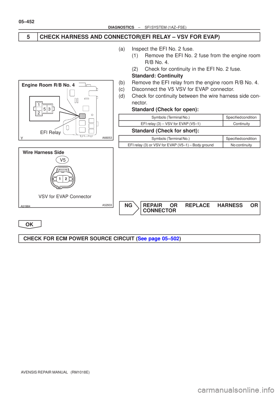
A66053
Engine Room R/B No. 4EFI Relay
������A52933
Wire Harness SideVSV for EVAP Connector
V5
05±452
±
DIAGNOSTICS SFI SYSTEM(1AZ±FSE)
AVENSIS REPAIR MANUAL (RM1018E)
5CHECK HARNESS AND CONNECTOR(EFI RELAY ± VSV FOR EVAP)
(a)Inspect the EFI No. 2 fuse. (1)Remove the EFI No. 2 fuse from the engine room
R/B No. 4.
(2)Check for continuity in the EFI No. 2 fuse.
Standard: Continuity
(b)Remove the EFI relay from the engine room R/B No. 4.
(c)Disconnect the V5 VSV for EVAP connector.
(d)Check for continuity between the wire harness side con- nector.
Standard (Check for open):
Symbols (Terminal No.)Specified condition
EFI relay (3) ± VSV for EVAP (V5±1)Continuity
Standard (Check for short):
Symbols (Terminal No.)Specified condition
EFI relay (3) or VSV for EVAP (V5±1) ± Body groundNo continuity
NGREPAIR OR REPLACE HARNESS OR CONNECTOR
OK
CHECK FOR ECM POWER SOURCE CIRCUIT (See page 05±502)

AVENSIS REPAIR MANUAL (RM1018E)
9REPLACE CAMSHAFT TIMING GEAR ASSY (See page 14±240)
GO
10CHECK BLOCKAGE(OCV, OIL CHECK VALVE AND OIL HOLE)
NGREPAIR OR R")

E9E11
E1 (±)ECM Connector
05±468
±
DIAGNOSTICS SFI SYSTEM(1AZ±FSE)
AVENSIS REPAIR MANUAL (RM1018E)
1CHECK FUSE(EFI FUSE)
(a)Remove the EFI f")