Page 631 of 5135

A76859
Hand±held
Tester
DLC3
05±530
±
DIAGNOSTICS ECD SYSTEM(1CD±FTV)
AVENSIS REPAIR MANUAL (RM1018E)
(c)Inspect the battery voltage. Battery voltage: 11 to 14 V
If voltage is below 11V, recharge the battery before proceeding.
(d)Check the CHK ENG.
(1)The CHK ENG lamp comes on when the ignitionswitch is turned ON and the engine is not running.
HINT:
If the CHK ENG is not illuminate, troubleshoot the combination
meter.
(2)When the engine is started, the CHK ENG shouldgo off. If the lamp remains on, it means that the diag-
nosis system has detected a malfunction or ab-
normality in the system.
2.DTC CHECK (Normal Mode):
NOTICE:
Hand±held tester only:
When the diagnosis system is switched from the normal
mode to the check mode, it erases all DTCs and freeze
frame data recorded in the normal mode. So before switch-
ing modes, always check the DTCs and freeze frame data,
and then write them down.
(a)Checking DTCs using the hand±held tester. (1)Connect the hand±held tester to the DLC3.
(2)Turn the ignition switch ON and switch the hand±held tester main switch ON.
(3)Use the hand±held tester to check the DTCs and freeze frame data and then write them down. If you
need help with the hand±held tester, refer to the
hand±held tester's instruction book).
(4)See page 05±544 to confirm the details of the
DTCs.
(b) Clearing the DTCs using the hand±held tester: (1) Connect the hand±held tester to the DLC3.
(2) Turn the ignition switch ON.
(3) When operating the hand±held tester to erase thecodes, the DTCs and freeze frame data will be
erased. (See the hand±held tester's instruction
book for operating instructions.)
(c) Clearing the DTCs not using the hand±held tester:
(1) Disconnect the battery terminal or remove the EFIand ETCS fuses from the engine room R/B for more
than 60 seconds.
Page 633 of 5135
05±532
± DIAGNOSTICSECD SYSTEM (1CD±FTV)
AVENSIS REPAIR MANUAL (RM1018E)
(c) Clearing the DTCs not using the hand±held tester:
(1) Disconnect the battery terminal or remove the EFI
and ETCS fuses from the engine room R/B for more
than 60 seconds.
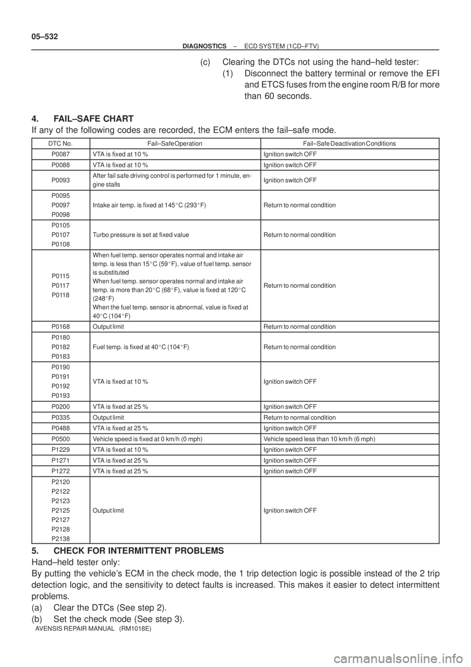
4. FAIL±SAFE CHART
If any of the following codes are recorded, the ECM enters the fail±safe mode.
DTC No.Fail±Safe OperationFail±Safe Deactivation Conditions
P0087VTA is fixed at 10 %Ignition switch OFF
P0088VTA is fixed at 10 %Ignition switch OFF
P0093After fail safe driving control is performed for 1 minute, en-
gine stallsIgnition switch OFF
P0095
P0097
P0098
Intake air temp. is fixed at 145�C (293�F)Return to normal condition
P0105
P0107
P0108
Turbo pressure is set at fixed valueReturn to normal condition
P0115
P0117
P0118
When fuel temp. sensor operates normal and intake air
temp. is less than 15�C (59�F), value of fuel temp. sensor
is substituted
When fuel temp. sensor operates normal and intake air
temp. is more than 20�C (68�F), value is fixed at 120�C
(248�F)
When the fuel temp. sensor is abnormal, value is fixed at
40�C (104�F)
Return to normal condition
P0168Output limitReturn to normal condition
P0180
P0182
P0183
Fuel temp. is fixed at 40�C (104�F)Return to normal condition
P0190
P0191
P0192
P0193
VTA is fixed at 10 %Ignition switch OFF
P0200VTA is fixed at 25 %Ignition switch OFF
P0335Output limitReturn to normal condition
P0488VTA is fixed at 25 %Ignition switch OFF
P0500Vehicle speed is fixed at 0 km/h (0 mph)Vehicle speed less than 10 km/h (6 mph)
P1229VTA is fixed at 10 %Ignition switch OFF
P1271VTA is fixed at 25 %Ignition switch OFF
P1272VTA is fixed at 25 %Ignition switch OFF
P2120
P2122
P2123
P2125
P2127
P2128
P2138
Output limitIgnition switch OFF
5. CHECK FOR INTERMITTENT PROBLEMS
Hand±held tester only:
By putting the vehicle's ECM in the check mode, the 1 trip detection logic is possible instead of the 2 trip
detection logic, and the sensitivity to detect faults is increased. This makes it easier to detect intermittent
problems.
(a) Clear the DTCs (See step 2).
(b) Set the check mode (See step 3).
Page 711 of 5135
± DIAGNOSTICSECD SYSTEM (1CD±FTV)
05±623
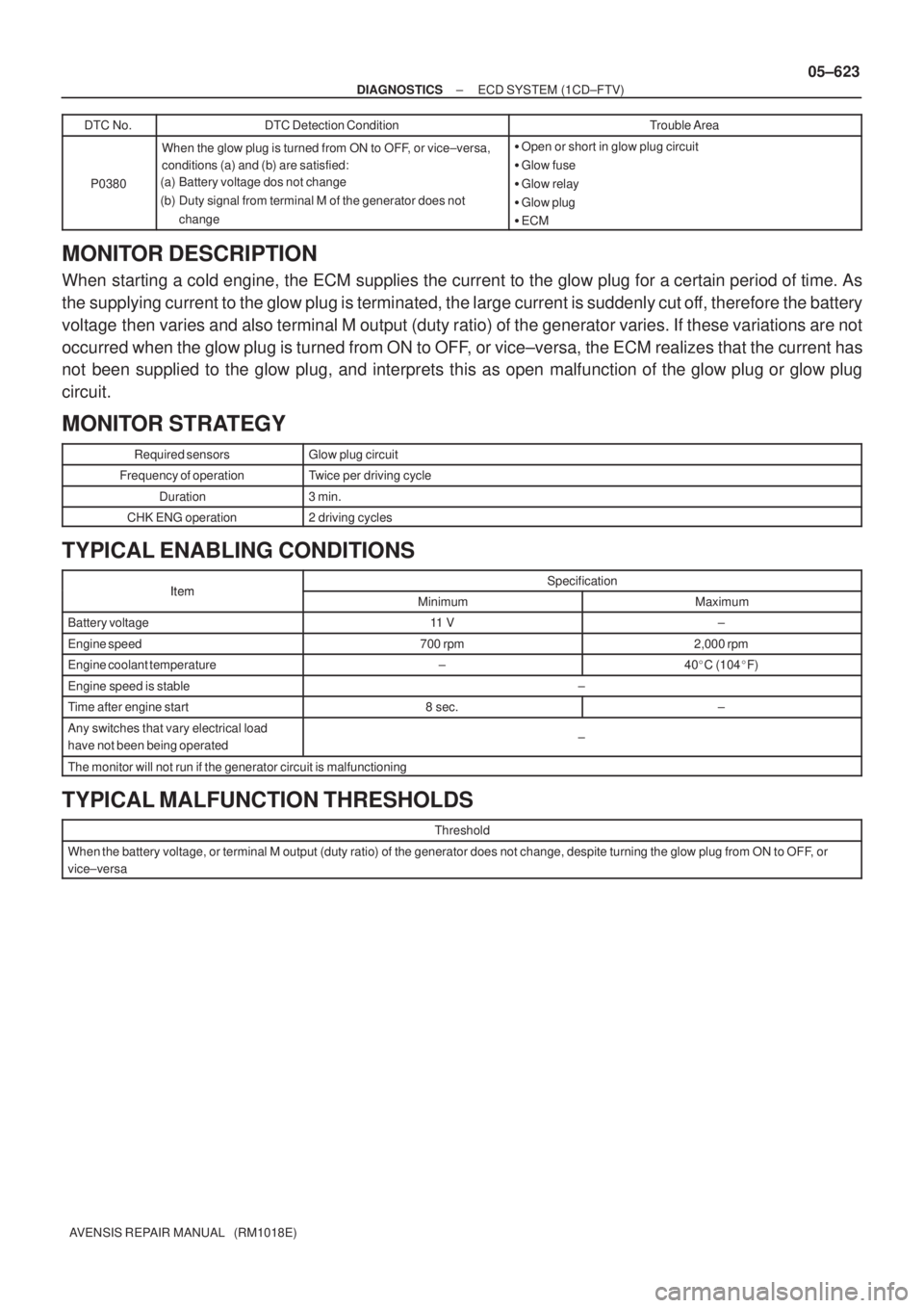
AVENSIS REPAIR MANUAL (RM1018E)DTC No.
DTC Detection ConditionTrouble Area
P0380
When the glow plug is turned from ON to OFF, or vice±versa,
conditions (a) and (b) are satisfied:
(a) Battery voltage dos not change
(b) Duty signal from terminal M of the generator does not
change�Open or short in glow plug circuit
�Glow fuse
�Glow relay
�Glow plug
�ECM
MONITOR DESCRIPTION
When starting a cold engine, the ECM supplies the current to the glow plug for a certain period of time. As
the supplying current to the glow plug is terminated, the large current is suddenly cut off, therefore the battery
voltage then varies and also terminal M output (duty ratio) of the generator varies. If these variations are not
occurred when the glow plug is turned from ON to OFF, or vice±versa, the ECM realizes that the current has
not been supplied to the glow plug, and interprets this as open malfunction of the glow plug or glow plug
circuit.
MONITOR STRATEGY
Required sensorsGlow plug circuit
Frequency of operationTwice per driving cycle
Duration3 min.
CHK ENG operation2 driving cycles
TYPICAL ENABLING CONDITIONS
ItemSpecificationItemMinimumMaximum
Battery voltage11 V±
Engine speed700 rpm2,000 rpm
Engine coolant temperature±40�C (104�F)
Engine speed is stable±
Time after engine start8 sec.±
Any switches that vary electrical load
have not been being operated±
The monitor will not run if the generator circuit is malfunctioning
TYPICAL MALFUNCTION THRESHOLDS
Threshold
When the battery voltage, or terminal M output (duty ratio) of the generator does not change, despite turning the glow plug from ON to OFF, or
vice±versa
Page 714 of 5135
A33913
A80987
Engine Room R/B No. 3GLOW
Fuse
B08263
OhmmeterContinuity
05±626
±
DIAGNOSTICS ECD SYSTEM(1CD±FTV)
AVENSIS REPAIR MANUAL (RM1018E)
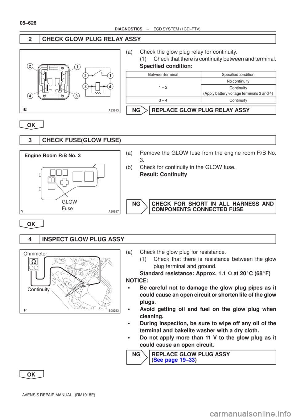
2CHECK GLOW PLUG RELAY ASSY
(a)Check the glow plug relay for continuity. (1)Check that there is continuity between and terminal.
Specified condition:
Between terminalSpecified condition
No continuity
1 ± 2Continuity
(Apply battery voltage terminals 3 and 4)
3 ± 4Continuity
NGREPLACE GLOW PLUG RELAY ASSY
OK
3CHECK FUSE(GLOW FUSE)
(a)Remove the GLOW fuse from the engine room R/B No. 3.
(b)Check for continuity in the GLOW fuse. Result: Continuity
NGCHECK FOR SHORT IN ALL HARNESS AND COMPONENTS CONNECTED FUSE
OK
4INSPECT GLOW PLUG ASSY
(a)Check the glow plug for resistance. (1)Check that there is resistance between the glow
plug terminal and ground.
Standard resistance: Approx. 1.1 � at 20 �C (68 �F)
NOTICE:
�Be careful not to damage the glow plug pipes as it
could cause an open circuit or shorten life of the glow
plugs.
�Avoid getting oil and fuel on the glow plug when
cleaning.
�During inspection, be sure to wipe off any oil of the
terminal and bakelite washer with a dry cloth.
�Do not apply more than 11 V to the glow plug as it
could cause an open circuit.
NGREPLACE GLOW PLUG ASSY (See page 19±33)
OK
Page 744 of 5135
A79096
Driver Side J/BIGN Fuse
B50489Ignition Switch
I13
A18294
E1 (±)MREL (+)
ECM Connecter
E12E9
05±688
±
DIAGNOSTICS ECD SYSTEM(1CD±FTV)
AVENSIS REPAIR MANUAL (RM1018E)
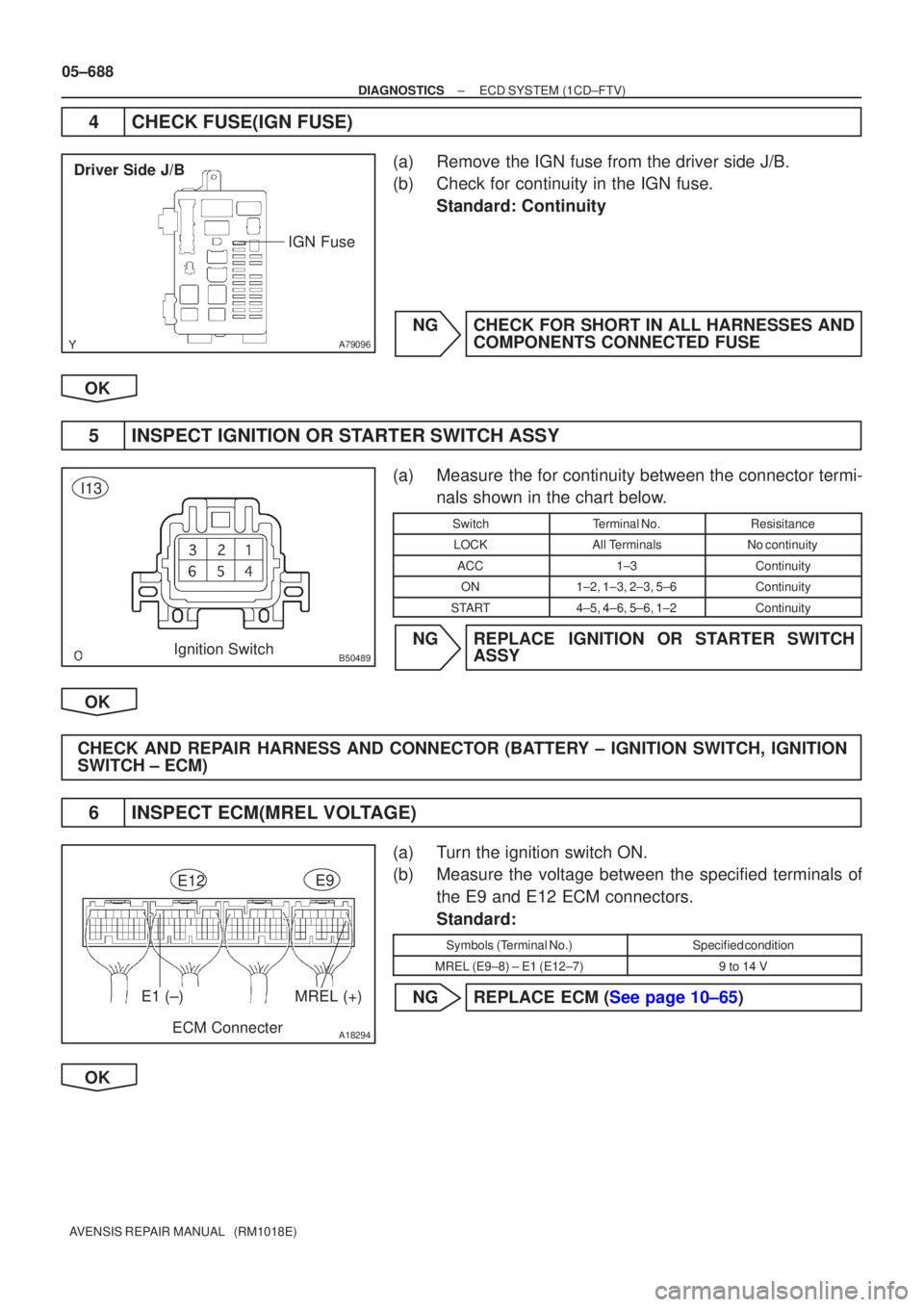
4CHECK FUSE(IGN FUSE)
(a)Remove the IGN fuse from the driver side J/B.
(b)Check for continuity in the IGN fuse. Standard: Continuity
NGCHECK FOR SHORT IN ALL HARNESSES AND COMPONENTS CONNECTED FUSE
OK
5INSPECT IGNITION OR STARTER SWITCH ASSY
(a)Measure the for continuity between the connector termi- nals shown in the chart below.
SwitchTerminal No.Resisitance
LOCKAll TerminalsNo continuity
ACC1±3Continuity
ON1±2, 1±3, 2±3, 5±6Continuity
START4±5, 4±6, 5±6, 1±2Continuity
NGREPLACE IGNITION OR STARTER SWITCH ASSY
OK
CHECK AND REPAIR HARNESS AND CONNECTOR (BATTERY ± IGNITION SWITCH, IGNITION
SWITCH ± ECM)
6INSPECT ECM(MREL VOLTAGE)
(a)Turn the ignition switch ON.
(b)Measure the voltage between the specified terminals of the E9 and E12 ECM connectors.
Standard:
Symbols (Terminal No.)Specified condition
MREL (E9±8) ± E1 (E12±7)9 to 14 V
NGREPLACE ECM (See page 10±65)
OK
Page 745 of 5135
A66054
Engine Room R/B No.1
EFI Fuse
B16200
± DIAGNOSTICSECD SYSTEM (1CD±FTV)
05±689
AVENSIS REPAIR MANUAL (RM1018E)
7 CHECK FUSE(EFI FUSE)
(a) Remove the EFI fuse from the engine room R/B No.1.
(b) Check for continuity in the EFI fuse.
Standard: Continuity
NG CHECK FOR SHORT IN ALL HARNESSES AND
COMPONENTS CONNECTED FUSE
OK
8 INSPECT EFI MAIN RELAY
(a) Remove the EFI MAIN relay from the engine room R/B
No.1.
(b) Inspect the EFI MAIN relay.
Standard:
Terminal No.ConditionSpecified condition
1 ± 2ConstantContinuity
UsuallyNo Continuity
3 ± 5Apply B+ between
Terminals 1 and 2Continuity
Terminal No.Specified condition
1 ± 2Continuity
No Continuity
3 ± 5Continuity
(Apply battery voltage terminals 1 and 2)
NG REPLACE EFI MAIN RELAY
OK
Page 776 of 5135
A66058
EFI fuse
Engine Room R/B No. 1
A80463
BATT (+)
E10E12
E1 (±)ECM Connector
05±648
±
DIAGNOSTICS ECD SYSTEM (1CD±FTV)
AVENSIS REPAIR MANUAL (RM1018E)
1 CHECK FUSE(EFI FUSE)
(a) Remove the EFI fuse from the engine room R/B No. 1.
(b) Check for continuity in the EFI fuse. Standard: Continuity
NG CHECK FOR SHORT IN ALL HARNESSES AND COMPONENTS CONNECTED FUSE
OK
2 INSPECT ECM(BATT VOLTAGE)
(a) Measure the voltage between the specified terminals of the E10 and E12 ECM connectors.
Standard:
Symbols (Terminal No.)Specified condition
BATT (E10±2) ± E1 (E12±7)9 to 14 V
OKREPLACE ECM (See page 10±65)
NG
Page 777 of 5135
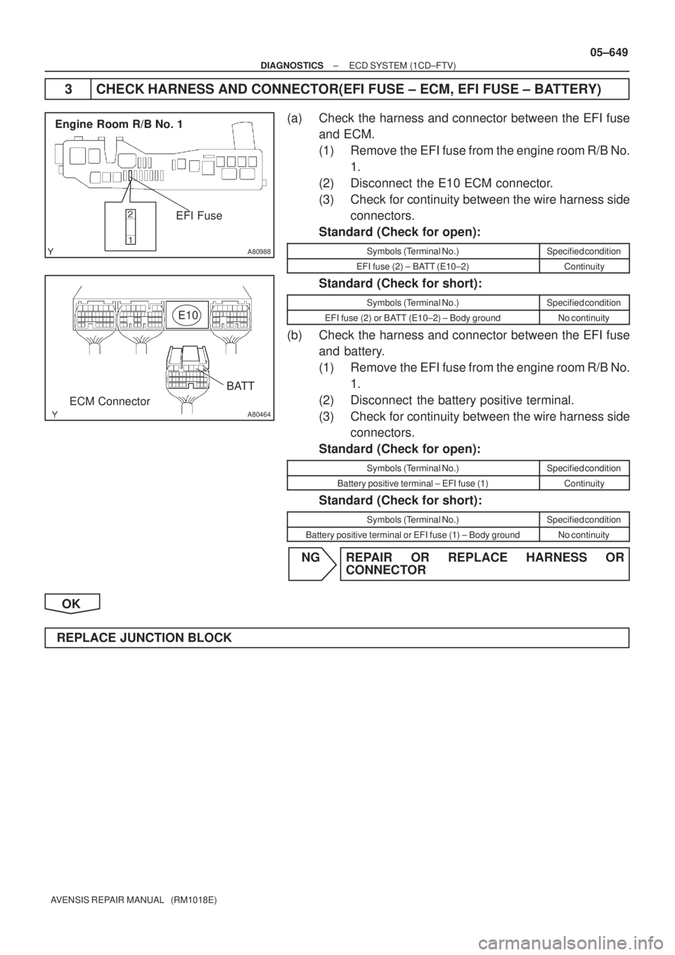
A80988
Engine Room R/B No. 1
EFI Fuse
A80464
BATT
ECM ConnectorE10
± DIAGNOSTICSECD SYSTEM (1CD±FTV)
05±649
AVENSIS REPAIR MANUAL (RM1018E)
3 CHECK HARNESS AND CONNECTOR(EFI FUSE ± ECM, EFI FUSE ± BATTERY)
(a) Check the harness and connector between the EFI fuse
and ECM.
(1) Remove the EFI fuse from the engine room R/B No.
1.
(2) Disconnect the E10 ECM connector.
(3) Check for continuity between the wire harness side
connectors.
Standard (Check for open):
Symbols (Terminal No.)Specified condition
EFI fuse (2) ± BATT (E10±2)Continuity
Standard (Check for short):
Symbols (Terminal No.)Specified condition
EFI fuse (2) or BATT (E10±2) ± Body groundNo continuity
(b) Check the harness and connector between the EFI fuse
and battery.
(1) Remove the EFI fuse from the engine room R/B No.
1.
(2) Disconnect the battery positive terminal.
(3) Check for continuity between the wire harness side
connectors.
Standard (Check for open):
Symbols (Terminal No.)Specified condition
Battery positive terminal ± EFI fuse (1)Continuity
Standard (Check for short):
Symbols (Terminal No.)Specified condition
Battery positive terminal or EFI fuse (1) ± Body groundNo continuity
NG REPAIR OR REPLACE HARNESS OR
CONNECTOR
OK
REPLACE JUNCTION BLOCK