Page 382 of 5135
MREL (+)
± DIAGNOSTICSSFI SYSTEM (1AZ±FE)
05±259
AVENSIS REPAIR MANUAL (RM1018E)
4 CHECK FUSE(IGN FUSE)")
A79096
Driver Side J/B
IGN Fuse
B50489Ignition Switch
I13
A18294ECM Connecter
E12E9
E1 (±)MREL (+)
± DIAGNOSTICSSFI SYSTEM (1AZ±FE)
05±259
AVENSIS REPAIR MANUAL (RM1018E)
4 CHECK FUSE(IGN FUSE)
(a) Remove the IGN fuse from the driver side J/B.
(b) Check for continuity in the IGN fuse.
Standard: Continuity
NG CHECK FOR SHORT IN ALL HARNESSES AND
COMPONENTS CONNECTED FUSE
OK
5 INSPECT IGNITION OR STARTER SWITCH ASSY
(a) Measure the resistance between the connector terminals
shown in the chart below.
SwitchTerminal No.Resisitance
LOCKAll Terminals1M� or more
ACC1±31� or less
ON1±2, 1±3, 2±3, 5±61� or less
START4±5, 4±6, 5±6, 1±21� or less
NG REPLACE IGNITION OR STARTER SWITCH
ASSY
OK
CHECK AND REPAIR HARNESS AND CONNECTOR (BATTERY ± IGNITION SWITCH, IGNITION
SWITCH ± ECM)
6 INSPECT ECM(MREL VOLTAGE)
(a) Turn the ignition switch ON.
(b) Measure the voltage between the terminals of the E9 and
E12 ECM connector.
Standard:
Symbols (Terminal No.)Specified condition
MREL (E9±8) ± E1 (E12±7)9 to 14 V
NG CHECK AND REPLACE ECM
OK
Page 383 of 5135
A66054
Engine Room R/B No.1
EFI Fuse
B16200
������
� �
A79065
Engine Room R/B No.4
EFI No.1 Fuse
05±260
± DIAGNOSTICSSFI SYSTEM (1AZ±FE)
AVENSIS REPAIR MANUAL (RM1018E)
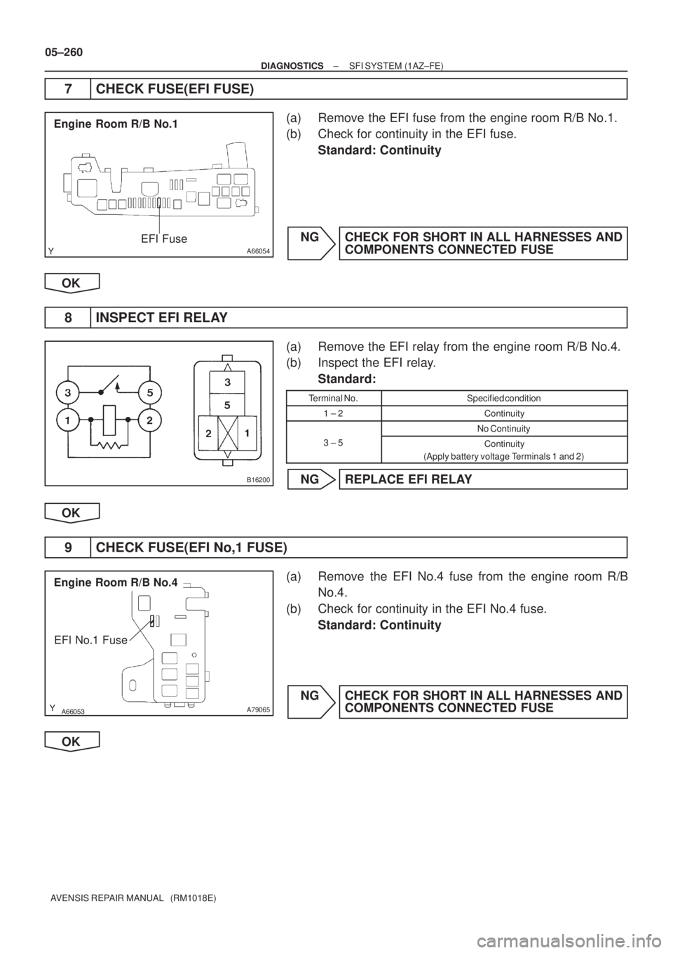
7 CHECK FUSE(EFI FUSE)
(a) Remove the EFI fuse from the engine room R/B No.1.
(b) Check for continuity in the EFI fuse.
Standard: Continuity
NG CHECK FOR SHORT IN ALL HARNESSES AND
COMPONENTS CONNECTED FUSE
OK
8 INSPECT EFI RELAY
(a) Remove the EFI relay from the engine room R/B No.4.
(b) Inspect the EFI relay.
Standard:
Terminal No.Specified condition
1 ± 2Continuity
No Continuity
3 ± 5Continuity
(Apply battery voltage Terminals 1 and 2)
NG REPLACE EFI RELAY
OK
9 CHECK FUSE(EFI No,1 FUSE)
(a) Remove the EFI No.4 fuse from the engine room R/B
No.4.
(b) Check for continuity in the EFI No.4 fuse.
Standard: Continuity
NG CHECK FOR SHORT IN ALL HARNESSES AND
COMPONENTS CONNECTED FUSE
OK
Page 384 of 5135

05±261
AVENSIS REPAIR MANUAL (RM1018E")
A66053
Engine Room R/B No.4
EFI Relay
������
�
A79066
Engine Room R/B No.4
EFI No.1 Fuse
1
2
A65748
MREL
E9
ECM Connector
+B
± DIAGNOSTICSSFI SYSTEM (1AZ±FE)
05±261
AVENSIS REPAIR MANUAL (RM1018E)
10 CHECK HARNESS AND CONNECTOR(EFI RELAY ± ECM, EFI RELAY ± BODY
GROUND)
(a) Check the harness and connector between the EFI relay
and ECM connector.
(1) Remove the EFI relay from the engine room R/B
No.4.
(2) Remove the EFI No.1 fuse from the engine room
R/B No.4.
(3) Disconnect the E9 ECM connector.
(4) Check for continuity between the wire harness side
connectors.
Standard (Check for open):
Symbols (Terminal No.)Specified condition
EFI relay (1) ± MREL (E9±8)
EFI relay (3) ± EFI No.1 fuse (1)Continuity
EFI No.1 fuse (2) ± +B (E9±1)
y
Standard (Check for short):
Symbols (Terminal No.)Specified condition
EFI relay (1) or MREL (E9±8) ± Body ground
EFI relay (3) or EFI No.1 fuse (1) ± Body groundNo continuity
EFI No.1 fuse (2) or +B (E9±1) ± Body ground
y
(b) Check the harness and connector between the EFI relay
and body ground.
(1) Remove the EFI relay from the engine room J/B
No.4.
(2) Check for continuity between the wire harness side
connector and the body ground.
Standard (Check for open):
Symbols (Terminal No.)Specified condition
EFI relay (2) ± Body groundContinuity
OK REPAIR OR REPLACE HARNESS OR
CONNECTOR
NG
CHECK AND REPAIR HARNESS AND CONNECTOR (TERMINAL +B OF ECM ± BATTERY POS-
ITIVE TERMINAL)
Page 392 of 5135

��
��
A76787
Wire Harness Side
+B HT
A7Bank 1 Sensor 1
A/F Connector AF+
AF±
A79114
A8Bank 2 Sensor 1 Wire Harness Side
+B
HT
A/F Connector
AF+
AF±
A65745
E12
HA1AHA2AA1A±
A1A+
A2A±
A2A+
B62793
A/F Sensor A/F Relay
Heater
Sensor
A1A+ HA1A
Duty
Control ECM
From
Battery
A/F Fuse
A1A±
MREL Reference (Bank 1 Sensor 1 System Drawing)
± DIAGNOSTICSSFI SYSTEM (1AZ±FE)
05±255
AVENSIS REPAIR MANUAL (RM1018E)
3 CHECK HARNESS AND CONNECTOR(ECM ± A/F SENSOR)
(a) Disconnect the A7 or A8 A/F sensor connector.
(b) Disconnect the E12 ECM connector.
(c) Check for continuity between the wire harness side con-
nectors.
Standard (Check for open):
Symbols (Terminal No.)Specified condition
AF+ (A7±3) ± A1A+ (E12±23)
AF± (A7±4) ± A1A± (E12±31)
HT (A7±1) ± HA1A (E12±6)ContinuityAF+ (A8±3) ± A2A+ (E12±22)Continuity
AF± (A8±4) ± A2A± (E12±30)
HT (A8±1) ± HA2A (E12±5)
Standard (Check for short):
Symbols (Terminal No.)Specified condition
AF+ (A7±3) or A1A+ (E12±23) ± Body ground
AF± (A7±4) or A1A± (E12±31) ± Body ground
HT (A7±1) or HA1A (E12±6) ± Body groundNo continuityAF+ (A8±3) or A2A+ (E12±22) ± Body groundNo continuity
AF± (A8±4) or A2A± (E12±30) ± Body ground
HT (A8±1) or HA2A (E12±5) ± Body ground
Page 395 of 5135

A79101
2 +B DUTY1
GND 3
I10
ISC Valve
G±R10
E12 RS")
A58697
Intake Air
Chamber
Throttle Valve
To Cylinder
ISC Valve
Valve
ECM
Signal From
Air
Cleaner
From
Terminal 2 of
EFI No.1 Fuse
(See Page 05±257)
A79101
2 +B DUTY1
GND 3
I10
ISC Valve
G±R10
E12 RSDECM
B±R 12
EA1 B±R
W±B7
E12 E1
BR
EF
±
DIAGNOSTICS SFI SYSTEM (1AZ±FE)
05±243
AVENSIS REPAIR MANUAL (RM1018E)
DTC P0511/33 IDLE AIR CONTROL CIRCUIT
CIRCUIT DESCRIPTION
The rotary solenoid type idle speed control (ISC) valve is lo-
cated under the throttle body and intake air bypassing the
throttle valve is directed to the idle speed control (ISC) valve
through the passage.
In this way the intake air volume bypassing the throttle valve is
regulated, controls the engine speed.
The ECM operates the idle speed control (ISC) valve only to
perform idle±up and provide feedback for the target idling
speed.
DTC No.DTC Detecting ConditionTrouble Area
P0511/33Idle speed continues to vary greatly from target speed
(1 trip detection logic)
�Open or short in idle speed control (ISC) valve circuit
� Idle speed control (ISC) valve is stuck or closed
� A/C switch circuit
� Air induction system
� ECM
WIRING DIAGRAM
INSPECTION PROCEDURE
HINT:
Read freeze frame data using \f�� �� ����\b� \f��\f�
� Freeze frame data records the engine conditions when
a malfunction is detected. When troubleshooting, it is useful for determi\
ning whether the vehicle was running
or stopped, the engine was warmed up or not, the air±fuel ratio was lea\
n or rich, etc. at the time of the mal-
function.
05C74±01
Page 408 of 5135

AVENSIS")
A79096
Driver Side J/B
IGN Fuse
A54393
+B
Ignition Coil and Igniter Connector Wire Harness Side
I1
I2I3I4
������A79064IG2 Relay
Engine Room R/B No.4
05±238
± DIAGNOSTICSSFI SYSTEM (1AZ±FE)
AVENSIS REPAIR MANUAL (RM1018E)
9 CHECK FUSE(IGN)
(a) Remove the IGN fuse from the driver side J/B.
(b) Check for continuity in the IGN fuse.
Standard: Continuity
NG CHECK FOR SHORT IN ALL HARNESS AND
COMPONENTS CONNECTED FUSE
OK
10 CHECK HARNESS AND CONNECTOR(IG2 RELAY ± IGNITION COIL AND IGNITER)
(a) Disconnect the I1, I2, I3 or I4 ignition coil and igniter con-
nector.
(b) Remove the IG2 relay from the engine room R/B No.4.
(c) Check for continuity between the wire harness side con-
nectors.
Standard (Check for open):
Symbols (Terminal No.)Specified condition
+B (I1±1) ± IG2 relay (3)
+B (I2±1) ± IG2 relay (3)Continuity+B (I3±1) ± IG2 relay (3)Continuity
+B (I4±1) ± IG2 relay (3)
Standard (Check for short):
Symbols (Terminal No.)Specified condition
+B (I1±1) or IG2 relay (3) ± Body ground
+B (I2±1) or IG2 relay (3) ± Body groundNo continuity+B (I3±1) or IG2 relay (3) ± Body groundNo continuity
+B (I4±1) or IG2 relay (3) ± Body ground
NG REPAIR OR REPLACE HARNESS OR
CONNECTOR
OK
Page 409 of 5135
A66267
IG2 Wire Harness Side
Ignition Switch Connector
I13
A79103
Driver Side J/B
IGN Fuse12
������A79064
Engine Room R/B No.4
IG2 Relay
± DIAGNOSTICSSFI SYSTEM (1AZ±FE)
05±239
AVENSIS REPAIR MANUAL (RM1018E)
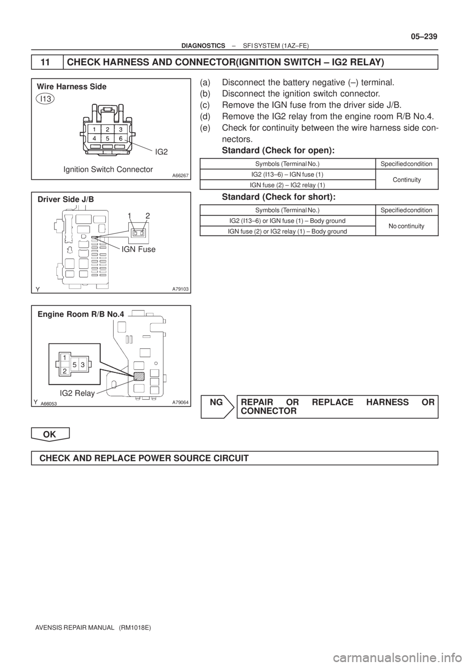
11 CHECK HARNESS AND CONNECTOR(IGNITION SWITCH ± IG2 RELAY)
(a) Disconnect the battery negative (±) terminal.
(b) Disconnect the ignition switch connector.
(c) Remove the IGN fuse from the driver side J/B.
(d) Remove the IG2 relay from the engine room R/B No.4.
(e) Check for continuity between the wire harness side con-
nectors.
Standard (Check for open):
Symbols (Terminal No.)Specified condition
IG2 (I13±6) ± IGN fuse (1)ContinuityIGN fuse (2) ± IG2 relay (1)Continuity
Standard (Check for short):
Symbols (Terminal No.)Specified condition
IG2 (I13±6) or IGN fuse (1) ± Body groundNo continuityIGN fuse (2) or IG2 relay (1) ± Body groundNo continuity
NG REPAIR OR REPLACE HARNESS OR
CONNECTOR
OK
CHECK AND REPLACE POWER SOURCE CIRCUIT
Page 418 of 5135

05±309
AVENSIS REPAIR MANUAL (RM1018E)
DIAGNOSTIC TROUBLE CODE CHART
HINT:
Parameters listed in the chart may not be exactly the same as your readings")
05CID±01
±
DIAGNOSTICS SFI SYSTEM(1AZ±FSE)
05±309
AVENSIS REPAIR MANUAL (RM1018E)
DIAGNOSTIC TROUBLE CODE CHART
HINT:
Parameters listed in the chart may not be exactly the same as your readings due to\
the type of instrument
or other factors.�
If a malfunction code is displayed during the DTC check in the check mode, check the circuit f\
or the codes
listed in the table below. For details of each code, refer to the ''See page '' under the respective ''DTC No.''
in the DTC chart.
�
�
��
�\f�� �������������� \b���
������ ����*1
CHK ENG �����
P0010
(05±322)Camshaft Position ºAº Actuator
Circuit (Bank 1)� Open or short in OCV circuit
� OCV
� ECM
��
P0011
(05±325)Camshaft Position ºAº ±Timing
Over± Advanced or System Per-
formance (Bank 1)� Valve timing
� OCV
�VVT controller assembly
��
P0012
(05±325)Camshaft Position ºAº ±Timing
Over± Retarded (Bank 1)� VVT controller assembly
� ECM
��
P0016
(05±329)Crankshaft Position ± Camshaft
Position Correlation (Bank 1
Sensor A)� Mechanical system (Timing chain has jumped a tooth, chain
stretched)
� ECM
��
P0031
(05±330)Oxygen Sensor Heater Circuit
Low (Bank 1 Sensor 1)
� Open in heater circuit of heated oxygen sensor
� Heated oxygen sensor heater
� EFI relay
� EFI fuse
� EFI No. 2 fuse
� ECM
��
P0032
(05±330)Oxygen Sensor Heater Circuit
High (Bank 1 Sensor 1)� Short in heater circuit of heated oxygen sensor
� Heated oxygen sensor heater
� ECM
��
P0037
(05±330)Oxygen Sensor Heater Control
Circuit Low (Bank 1 Sensor 2)� Same as DTC No. P0031��
P0038
(05±330)Oxygen Sensor Heater Control
Circuit High (Bank 1 Sensor 2)� Same as DTC No. P0032��
P0051
(05±330)Oxygen Sensor Heater Circuit
Low (Bank 2 Sensor 1)� Same as DTC No. P0031��
P0052
(05±330)Oxygen Sensor Heater Circuit
High (Bank 2 Sensor 1)� Same as DTC No. P0032��
P0057
(05±330)Oxygen Sensor Heater Control
Circuit Low (Bank 2 Sensor 2)� Same as DTC No. P0031��
P0058
(05±330)Oxygen Sensor Heater Control
Circuit High (Bank 2 Sensor 2)� Same as DTC No. P0032��
P0100
(05±336)Mass or volume Air Flow Circuit
Ohti ifltiit
��
P0102
(05±336)Mass or volume Air Flow Circuit
Low Input� Open or short in mass air flow meter circuit
� Mass air flow meter
�ECM
��
P0103
(05±336)Mass or volume Air Flow Circuit
High Input�ECM
��
P0105
(05±342)Manifold Absolute Pressure/
Barometric Pressure Circuit��
P0107
(05±342)Manifold Absolute Pressure/
Barometric Pressure Circuit Low
Input� Open or short in manifold absolute pressure sensor circuit
� Manifold absolute pressure sensor
�ECM
��
P0108
(05±342)Manifold Absolute Pressure/
Barometric Pressure Circuit High
Input�ECM
��