Page 5017 of 5135

I42012
(1)
(3)
I42013
(4)
(1)
I42012
(1)
(3)
– DIAGNOSTICSCRUISE CONTROL SYSTEM (2AZ–FSE)(From
February, 2004)05–311
AVENSIS REPAIR MANUAL SUPPLEMENT
(RM1098E)
4. DTC CLEAR
(a) The following methods will erase the DTCs and freeze frame data.
(1) The intelligent tester II can be used to erase the codes.
(2) Disconnecting the battery terminal or EFI No.1 fuse can also erase the codes.
(b) After completing repair, the DTC retained in the memory can be cleared by removing the EFI No.1 fuse
for 1 minute or more with the ignition switch off.
(c) Check that the normal system code is displayed after connecting the fuse.
5. PROBLEM SYMPTOM CONFIRMATION (ROAD TEST)
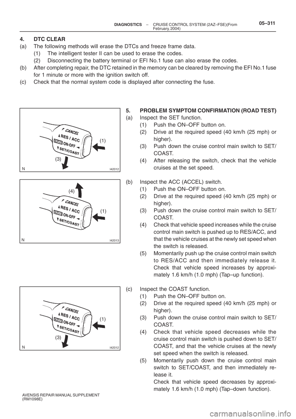
(a) Inspect the SET function.
(1) Push the ON–OFF button on.
(2) Drive at the required speed (40 km/h (25 mph) or
higher).
(3) Push down the cruise control main switch to SET/
COAST.
(4) After releasing the switch, check that the vehicle
cruises at the set speed.
(b) Inspect the ACC (ACCEL) switch.
(1) Push the ON–OFF button on.
(2) Drive at the required speed (40 km/h (25 mph) or
higher).
(3) Push down the cruise control main switch to SET/
COAST.
(4) Check that vehicle speed increases while the cruise
control main switch is pushed up to RES/ACC, and
that the vehicle cruises at the newly set speed when
the switch is released.
(5) Momentarily push up the cruise control main switch
to RES/ACC and then immediately release it.
Check that vehicle speed increases by approxi-
mately 1.6 km/h (1.0 mph) (Tap–up function).
(c) Inspect the COAST function.
(1) Push the ON–OFF button on.
(2) Drive at the required speed (40 km/h (25 mph) or
higher).
(3) Push down the cruise control main switch to SET/
COAST.
(4) Check that vehicle speed decreases while the
cruise control main switch is pushed down to SET/
COAST, and that the vehicle cruises at the newly
set speed when the switch is released.
(5) Momentarily push down the cruise control main
switch to SET/COAST, and then immediately re-
lease it.
Check that vehicle speed decreases by approxi-
mately 1.6 km/h (1.0 mph) (Tap–down function).
Page 5088 of 5135

056HK–07
05–316–
DIAGNOSTICS CRUISE CONTROL SYSTEM (2AZ–FSE)(From
February, 2004)
AVENSIS REPAIR MANUAL SUPPLEMENT
(RM1098E)
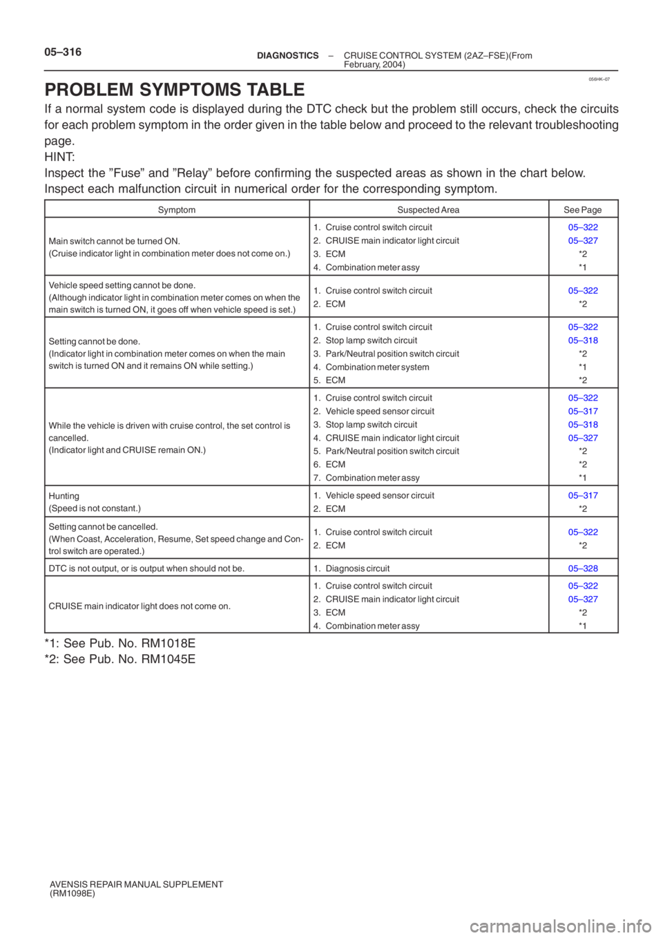
PROBLEM SYMPTOMS TABLE
If a normal system code is displayed during the DTC check but the problem still occurs, check the circuits
for each problem symptom in the order given in the table below and proceed \
to the relevant troubleshooting
page.
HINT:
Inspect the ”Fuse” and ”Relay” before confirming the suspected area\
s as shown in the chart below.
Inspect each malfunction circuit in numerical order for the correspondin\
g symptom.
SymptomSuspected AreaSee Page
Main switch cannot be turned ON.
(Cruise indicator light in combination meter does not come on.)
1. Cruise control switch circuit
2. CRUISE main indicator light circuit
3. ECM
4. Combination meter assy05–322
05–327 *2
*1
Vehicle speed setting cannot be done.
(Although indicator light in combination meter comes on when the
main switch is turned ON, it goes off when vehicle speed is set.)1. Cruise control switch circuit
2. ECM05–322*2
Setting cannot be done.
(Indicator light in combination meter comes on when the main
switch is turned ON and it remains ON while setting.)
1. Cruise control switch circuit
2. Stop lamp switch circuit
3. Park/Neutral position switch circuit
4. Combination meter system
5. ECM05–322
05–318*2
*1
*2
While the vehicle is driven with cruise control, the set control is
cancelled.
(Indicator light and CRUISE remain ON.)
1. Cruise control switch circuit
2. Vehicle speed sensor circuit
3. Stop lamp switch circuit
4. CRUISE main indicator light circuit
5. Park/Neutral position switch circuit
6. ECM
7. Combination meter assy05–322
05–317
05–318
05–327*2
*2
*1
Hunting
(Speed is not constant.)1. Vehicle speed sensor circuit
2. ECM05–317
*2
Setting cannot be cancelled.
(When Coast, Acceleration, Resume, Set speed change and Con-
trol switch are operated.)1. Cruise control switch circuit
2. ECM05–322*2
DTC is not output, or is output when should not be.1. Diagnosis circuit05–328
CRUISE main indicator light does not come on.
1. Cruise control switch circuit
2. CRUISE main indicator light circuit
3. ECM
4. Combination meter assy05–322
05–327*2
*1
*1: See Pub. No. RM1018E
*2: See Pub. No. RM1045E
Page 5097 of 5135
B66033
B660325 Clamps
or
or or
or
or
or 71–12
– INSTRUMENT PANEL/METERINSTRUMENT PANEL SUB–ASSY LOWER (From
February, 2004)
AVENSIS REPAIR MANUAL SUPPLEMENT
(RM1098E)
34. REMOVE HEATER TO REGISTER DUCT NO.2
(a) Remove the screw , clip and the heater to register duct
No.2.
35. REMOVE INSTRUMENT PANEL LOWER ASSY
(a) Disconnect the hood lock control cable.
(b) Using a clip remover, remove the 2 clips.
(c) Remove the 2 bolts and 7 screws or .
(d) Disengage the 5 wire harness clamps.
(e) Remove the instrument panel lower assy.
36. REMOVE OUTER MIRROR SWITCH ASSY W/BEZEL
37. REMOVE FUSE BOX OPENING COVER
38. REMOVE GLOVE BOX LAMP ASSY
39. REMOVE INSTRUMENT PANEL BRACKET SUB–ASSY CENTER
(a) Remove the screw and the instrument panel bracket sub–assy center.