Page 33 of 5135

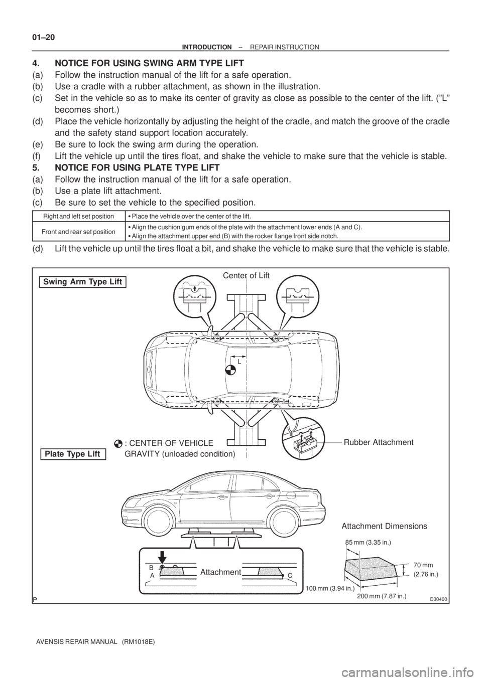
D30400
Swing Arm Type Lift
Plate Type LiftCenter of Lift
: CENTER OF VEHICLE
GRAVITY (unloaded condition)Rubber Attachment
AttachmentBAL
Attachment Dimensions
85 mm (3.35 in.)
200 mm (7.87 in.) 100 mm (3.94 in.)70 mm
(2.76 in.)
C
01±20
± INTRODUCTIONREPAIR INSTRUCTION
AVENSIS REPAIR MANUAL (RM1018E)
4. NOTICE FOR USING SWING ARM TYPE LIFT
(a) Follow the instruction manual of the lift for a safe operation.
(b) Use a cradle with a rubber attachment, as shown in the illustration.
(c) Set in the vehicle so as to make its center of gravity as close as possible to the center of the lift. (ºLº
becomes short.)
(d) Place the vehicle horizontally by adjusting the height of the cradle, and match the groove of the cradle
and the safety stand support location accurately.
(e) Be sure to lock the swing arm during the operation.
(f) Lift the vehicle up until the tires float, and shake the vehicle to make sure that the vehicle is stable.
5. NOTICE FOR USING PLATE TYPE LIFT
(a) Follow the instruction manual of the lift for a safe operation.
(b) Use a plate lift attachment.
(c) Be sure to set the vehicle to the specified position.
Right and left set position�Place the vehicle over the center of the lift.
Front and rear set position�Align the cushion gum ends of the plate with the attachment lower ends (A and C).
�Align the attachment upper end (B) with the rocker flange front side notch.
(d) Lift the vehicle up until the tires float a bit, and shake the vehicle to make sure that the vehicle is stable.
Page 148 of 5135

0313C±05
03±38
± SERVICE SPECIFICATIONSTIRE & WHEEL
AVENSIS REPAIR MANUAL (RM1018E)
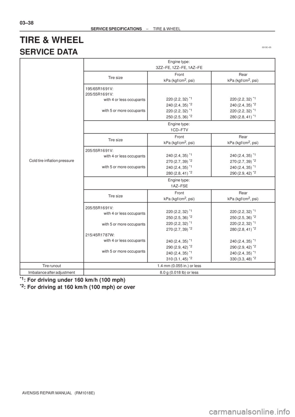
TIRE & WHEEL
SERVICE DATA
Engine type:
3ZZ±FE, 1ZZ±FE, 1AZ±FE
Tire sizeFront
kPa (kgf/cm2, psi)
Rear
kPa (kgf/cm2, psi)
195/65R16 91V:
205/55R16 91V:
with 4 or less occupants
with 5 or more occupants
220 (2.2, 32) *1
240 (2.4, 35) *2
220 (2.2, 32) *1
250 (2.5, 36) *2
220 (2.2, 32) *1
240 (2.4, 35) *2
220 (2.2, 32) *1
280 (2.8, 41) *1
Engine type:
1CD±FTV
Tire sizeFront
kPa (kgf/cm2, psi)
Rear
kPa (kgf/cm2, psi)
Cold tire inflation pressure
205/55R16 91V:
with 4 or less occupants
with 5 or more occupants
240 (2.4, 35) *1
270 (2.7, 39) *2
240 (2.4, 35) *1
280 (2.8, 41) *2
240 (2.4, 35) *1
270 (2.7, 39) *2
240 (2.4, 35) *1
290 (2.9, 42) *2
Engine type:
1AZ±FSE
Tire sizeFront
kPa (kgf/cm2, psi)
Rear
kPa (kgf/cm2, psi)
205/55R16 91V:
with 4 or less occupants
with 5 or more occupants
215/45R17 87W:
with 4 or less occupants
with 5 or more occupants220 (2.2, 32) *1
250 (2.5, 36) *2
220 (2.2, 32) *1
270 (2.7, 39) *2
240 (2.4, 35) *1
290 (2.9, 42) *2
240 (2.4, 35) *1
310 (3.1, 45) *2
220 (2.2, 32) *1
250 (2.5, 36) *2
220 (2.2, 32) *1
280 (2.8, 41) *2
240 (2.4, 35) *1
290 (2.9, 42) *2
240 (2.4, 35) *1
330 (3.3, 48) *2
Tire runout1.4 mm (0.055 in.) or less
Imbalance after adjustment8.0 g (0.018 lb) or less
*1: For driving under 160 km/h (100 mph)
*2: For driving at 160 km/h (100 mph) or over
Page 1577 of 5135
I35761
Combination Meter Assy
Fuse Block
Driver Side J/B
Center J/B
Ignition Switch
Engine Room J/B No.1 and R/B No.1
Engine Room R/B No.3FL MAIN
Battery
ALTAM2 DCC
J15
J/C AM1 IG1
AM2 IG2J/CJ/C
DOME
IGN
GAUGE1 IG1 Relay
AM1B±WC1120
22
21
5
W±B A
IL IP IJ IK B B±RIE4 IP111 B±R6 1
4 3
G±RG±YW±BW±BR±W J11
J26 J10 6 2 1
IE4 IP154
B±W218
7
5
9
1 DA
DB DH
DN1
ED11C11
C11
C11 W±R(*2) W±R
(*1) H
F F F
W±RJ26 6
B±W
(*2) (*1)
DH DH
DA 21 53J26 J26J8 J8CA
CA (*1) (*2)
(*1) (*2) (*1) (*2)
W±B 7
6
6 6
CA
CACD
CK
(*2)
(*1)
(*2) W±B
(*1) 1
11
2
1
2
1 1A
B
W3
33 1
2B±RR±W Diesel Engine Type (1CD±FTV):
B±W
*1: LHD Models
*2: RHD Models B±L
± DIAGNOSTICSCOMBINATION METER
05±1519
AVENSIS REPAIR MANUAL (RM1018E)
ENTIRE COMBINATION METER DOES NOT OPERATE
WIRING DIAGRAM
05C4L±01
Page 2811 of 5135

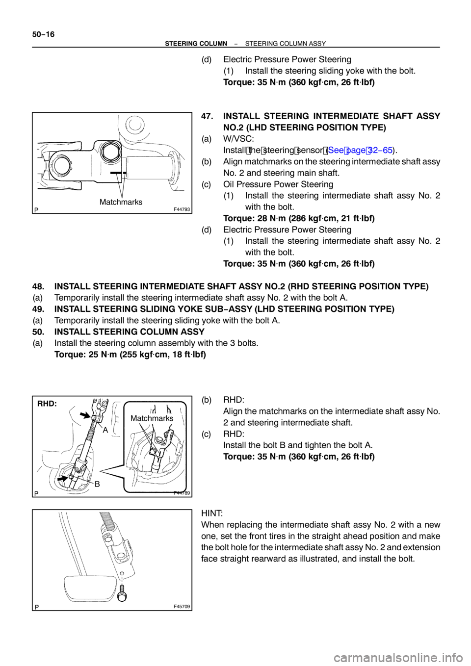
F44793Matchmarks
F44789
RHD:
Matchmarks
A
B
F45709
50−16
−
STEERING COLUMN STEERING COLUMN ASSY
(d) Electric Pressure Power Steering
(1) Install the steering sliding yoke with the bolt.
Torque: 35 N �m (360 kgf�cm, 26 ft �lbf)
47. INSTALL STEERING INTERMEDIATE SHAFT ASSY NO.2 (LHD STEERING POSITION TYPE)
(a) W/VSC:
Install the steering sensor (See page 32− 65).
(b) Align matchmarks on the steering intermediate shaft assy
No. 2 and steering main shaft.
(c) Oil Pressure Power Steering (1) Install the steering intermediate shaft assy No. 2
with the bolt.
Torque: 28 N �m (286 kgf�cm, 21 ft �lbf)
(d) Electric Pressure Power Steering (1) Install the steering intermediate shaft assy No. 2
with the bolt.
Torque: 35 N �m (360 kgf�cm, 26 ft �lbf)
48. INSTALL STEERING INTERMEDIATE SHAFT ASSY NO.2 (RHD STEERING POSITION TYPE)
(a) Temporarily install the steering intermediate shaft assy No. 2 with the bolt A.
49. INSTALL STEERING SLIDING YOKE SUB −ASSY (LHD STEERING POSITION TYPE)
(a) Temporarily install the steering sliding yoke with the bolt A.
50. INSTALL STEERING COLUMN ASSY
(a) Install the steering column assembly with the 3 bolts.
Torque: 25 N �m (255 kgf�cm, 18 ft �lbf)
(b) RHD: Align the matchmarks on the intermediate shaft assy No.
2 and steering intermediate shaft.
(c) RHD: Install the bolt B and tighten the bolt A.
Torque: 35 N �m (360 kgf�cm, 26 ft �lbf)
HINT:
When replacing the intermediate shaft assy No. 2 with a new
one, set the front tires in the straight ahead position and make
the bolt hole for the intermediate shaft assy No. 2 and extension
face straight rearward as illustrated, and install the bolt.
Page 2883 of 5135

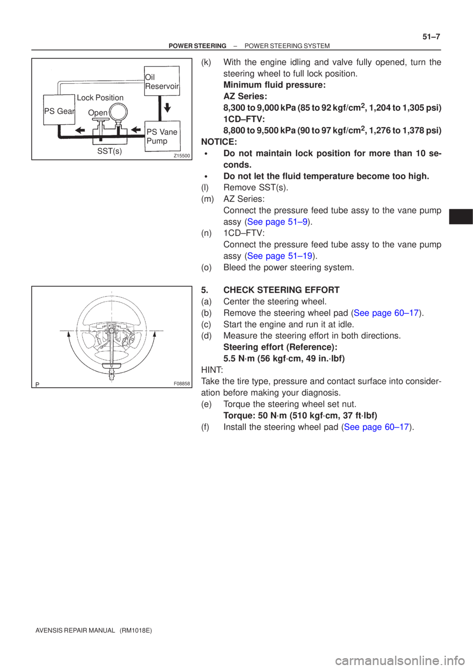
Z15500
Oil
ReservoirPS Vane
Pump
PS Gear
SST(s)
Open
Lock Position
F08858
±
POWER STEERING POWER STEERING SYSTEM
51±7
AVENSIS REPAIR MANUAL (RM1018E)
(k) With the engine idling and valve fully opened, turn the
steering wheel to full lock position.
Minimum fluid pressure:
AZ Series:
8,300 to 9,000 kPa (85 to 92 kgf/cm
2, 1,204 to 1,305 psi)
1CD±FTV:
8,800 to 9,500 kPa (90 to 97 kgf/cm
2, 1,276 to 1,378 psi)
NOTICE:
�Do not maintain lock position for more than 10 se-
conds.
�Do not let the fluid temperature become too high.
(l) Remove SST(s).
(m) AZ Series:
Connect the pressure feed tube assy to the vane pump
assy (See page 51±9).
(n) 1CD±FTV:
Connect the pressure feed tube assy to the vane pump
assy (See page 51±19).
(o) Bleed the power steering system.
5. CHECK STEERING EFFORT
(a) Center the steering wheel.
(b)Remove the steering wheel pad (See page 60±17).
(c) Start the engine and run it at idle.
(d) Measure the steering effort in both directions. Steering effort (Reference):
5.5 N´m (56 kgf´cm, 49 in.´lbf)
HINT:
Take the tire type, pressure and contact surface into consider-
ation before making your diagnosis.
(e) Torque the steering wheel set nut. Torque: 50 N´m (510 kgf´cm, 37 ft´lbf)
(f)Install the steering wheel pad (See page 60±17).
Page 4125 of 5135
0313C−07
− SERVICE SPECIFICATIONSTIRE & WHEEL
03−29
AVENSIS Supplement (RM1045E)
TIRE & WHEEL
SERVICE DATA
Engine type:
2AZ−FSE
Tire sizeFront
kPa (kgf/cm2, psi)
Rear
kPa (kgf/cm2, psi)
Cold tire inflation pressure
205/55R16 91V:
with 4 or less occupants
with 5 or more occupants
215/45R17 87W:
with 4 or less occupants
with 5 or more occupants220 (2.2, 32)*1
250 (2.5, 36)*2
220 (2.2, 32)*1
270 (2.7, 39)*2
240 (2.4, 35)*1
290 (2.9, 42)*2
240 (2.4, 35)*1
310 (3.1, 45)*2
220 (2.2, 32)*1
250 (2.5, 36)*2
220 (2.2, 32)*1
280 (2.8, 41)*2
240 (2.4, 35)*1
290 (2.9, 42)*2
240 (2.4, 35)*1
330 (3.3, 48)*2
Tire runout1.4 mm (0.055 in.) or less
Imbalance after adjustment8.0 g (0.018 lb) or less
*1: For driving under160 km/h (100 mph)
*2: For driving at160 km/h (100 mph) or over