Page 148 of 5135

0313C±05
03±38
± SERVICE SPECIFICATIONSTIRE & WHEEL
AVENSIS REPAIR MANUAL (RM1018E)
TIRE & WHEEL
SERVICE DATA
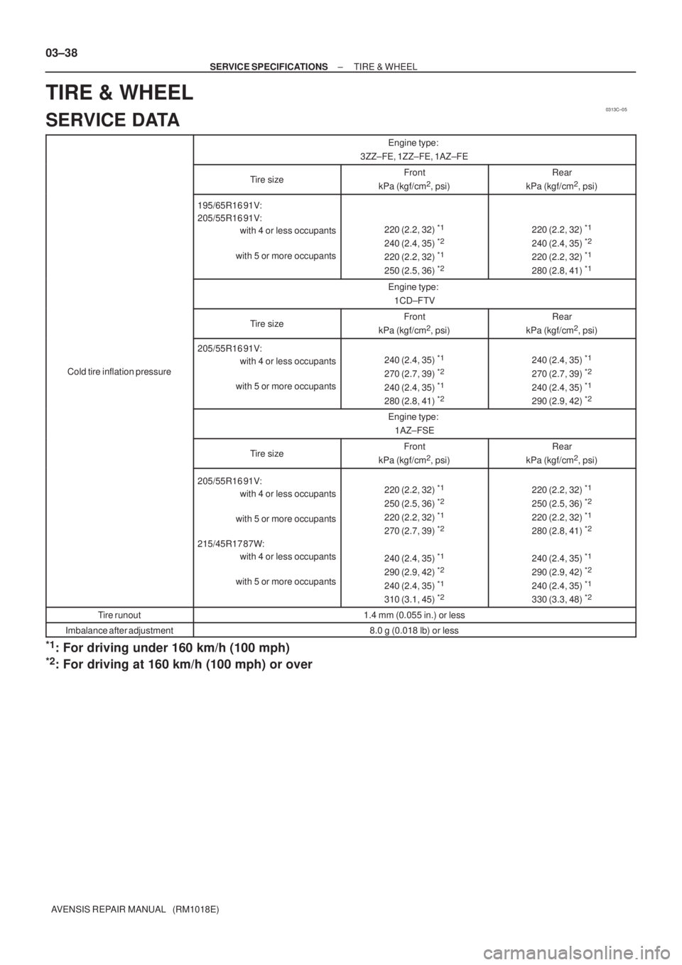
Engine type:
3ZZ±FE, 1ZZ±FE, 1AZ±FE
Tire sizeFront
kPa (kgf/cm2, psi)
Rear
kPa (kgf/cm2, psi)
195/65R16 91V:
205/55R16 91V:
with 4 or less occupants
with 5 or more occupants
220 (2.2, 32) *1
240 (2.4, 35) *2
220 (2.2, 32) *1
250 (2.5, 36) *2
220 (2.2, 32) *1
240 (2.4, 35) *2
220 (2.2, 32) *1
280 (2.8, 41) *1
Engine type:
1CD±FTV
Tire sizeFront
kPa (kgf/cm2, psi)
Rear
kPa (kgf/cm2, psi)
Cold tire inflation pressure
205/55R16 91V:
with 4 or less occupants
with 5 or more occupants
240 (2.4, 35) *1
270 (2.7, 39) *2
240 (2.4, 35) *1
280 (2.8, 41) *2
240 (2.4, 35) *1
270 (2.7, 39) *2
240 (2.4, 35) *1
290 (2.9, 42) *2
Engine type:
1AZ±FSE
Tire sizeFront
kPa (kgf/cm2, psi)
Rear
kPa (kgf/cm2, psi)
205/55R16 91V:
with 4 or less occupants
with 5 or more occupants
215/45R17 87W:
with 4 or less occupants
with 5 or more occupants220 (2.2, 32) *1
250 (2.5, 36) *2
220 (2.2, 32) *1
270 (2.7, 39) *2
240 (2.4, 35) *1
290 (2.9, 42) *2
240 (2.4, 35) *1
310 (3.1, 45) *2
220 (2.2, 32) *1
250 (2.5, 36) *2
220 (2.2, 32) *1
280 (2.8, 41) *2
240 (2.4, 35) *1
290 (2.9, 42) *2
240 (2.4, 35) *1
330 (3.3, 48) *2
Tire runout1.4 mm (0.055 in.) or less
Imbalance after adjustment8.0 g (0.018 lb) or less
*1: For driving under 160 km/h (100 mph)
*2: For driving at 160 km/h (100 mph) or over
Page 2556 of 5135

2801F±02
R03031
������F45650
Front (A)
(B)
± TIRE & WHEELWHEEL AND TIRE SYSTEM
28±1
AVENSIS REPAIR MANUAL (RM1018E)
WHEEL AND TIRE SYSTEM
INSPECTION
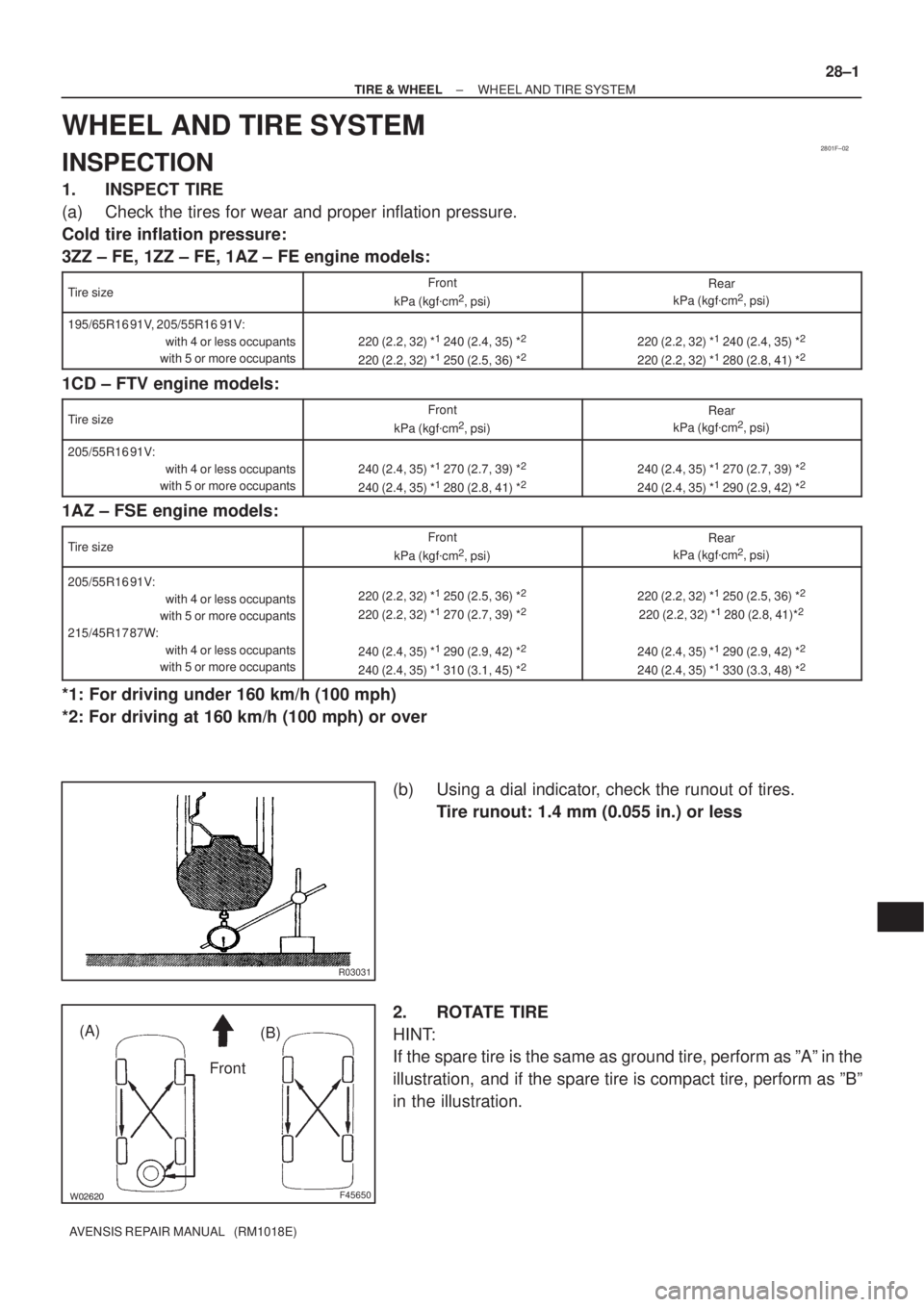
1. INSPECT TIRE
(a) Check the tires for wear and proper inflation pressure.
Cold tire inflation pressure:
3ZZ ± FE, 1ZZ ± FE, 1AZ ± FE engine models:
Tire sizeFront
kPa (kgf�cm2, psi)
Rear
kPa (kgf�cm2, psi)
195/65R16 91V, 205/55R16 91V:
with 4 or less occupants
with 5 or more occupants
220 (2.2, 32) *1 240 (2.4, 35) *2
220 (2.2, 32) *1 250 (2.5, 36) *2220 (2.2, 32) *1 240 (2.4, 35) *2
220 (2.2, 32) *1 280 (2.8, 41) *2
1CD ± FTV engine models:
Tire sizeFront
kPa (kgf�cm2, psi)
Rear
kPa (kgf�cm2, psi)
205/55R16 91V:
with 4 or less occupants
with 5 or more occupants
240 (2.4, 35) *1 270 (2.7, 39) *2
240 (2.4, 35) *1 280 (2.8, 41) *2240 (2.4, 35) *1 270 (2.7, 39) *2
240 (2.4, 35) *1 290 (2.9, 42) *2
1AZ ± FSE engine models:
Tire sizeFront
kPa (kgf�cm2, psi)
Rear
kPa (kgf�cm2, psi)
205/55R16 91V:
with 4 or less occupants
with 5 or more occupants
215/45R17 87W:
with 4 or less occupants
with 5 or more occupants220 (2.2, 32) *1 250 (2.5, 36) *2
220 (2.2, 32) *1 270 (2.7, 39) *2
240 (2.4, 35) *1 290 (2.9, 42) *2
240 (2.4, 35) *1 310 (3.1, 45) *2
220 (2.2, 32) *1 250 (2.5, 36) *2
220 (2.2, 32) *1 280 (2.8, 41)*2
240 (2.4, 35) *1 290 (2.9, 42) *2
240 (2.4, 35) *1 330 (3.3, 48) *2
*1: For driving under 160 km/h (100 mph)
*2: For driving at 160 km/h (100 mph) or over
(b) Using a dial indicator, check the runout of tires.
Tire runout: 1.4 mm (0.055 in.) or less
2. ROTATE TIRE
HINT:
If the spare tire is the same as ground tire, perform as ºAº in the
illustration, and if the spare tire is compact tire, perform as ºBº
in the illustration.
Page 2992 of 5135

H40181
Claw
Groove
H42905
Fig.1
Fig.2
Power Source
Safing
Sensor
Squibs
Deceleration
Sensor 60±6
± SUPPLEMENTAL RESTRAINT SYSTEMSUPPLEMENTAL RESTRAINT SYSTEM
AVENSIS REPAIR MANUAL (RM1018E)
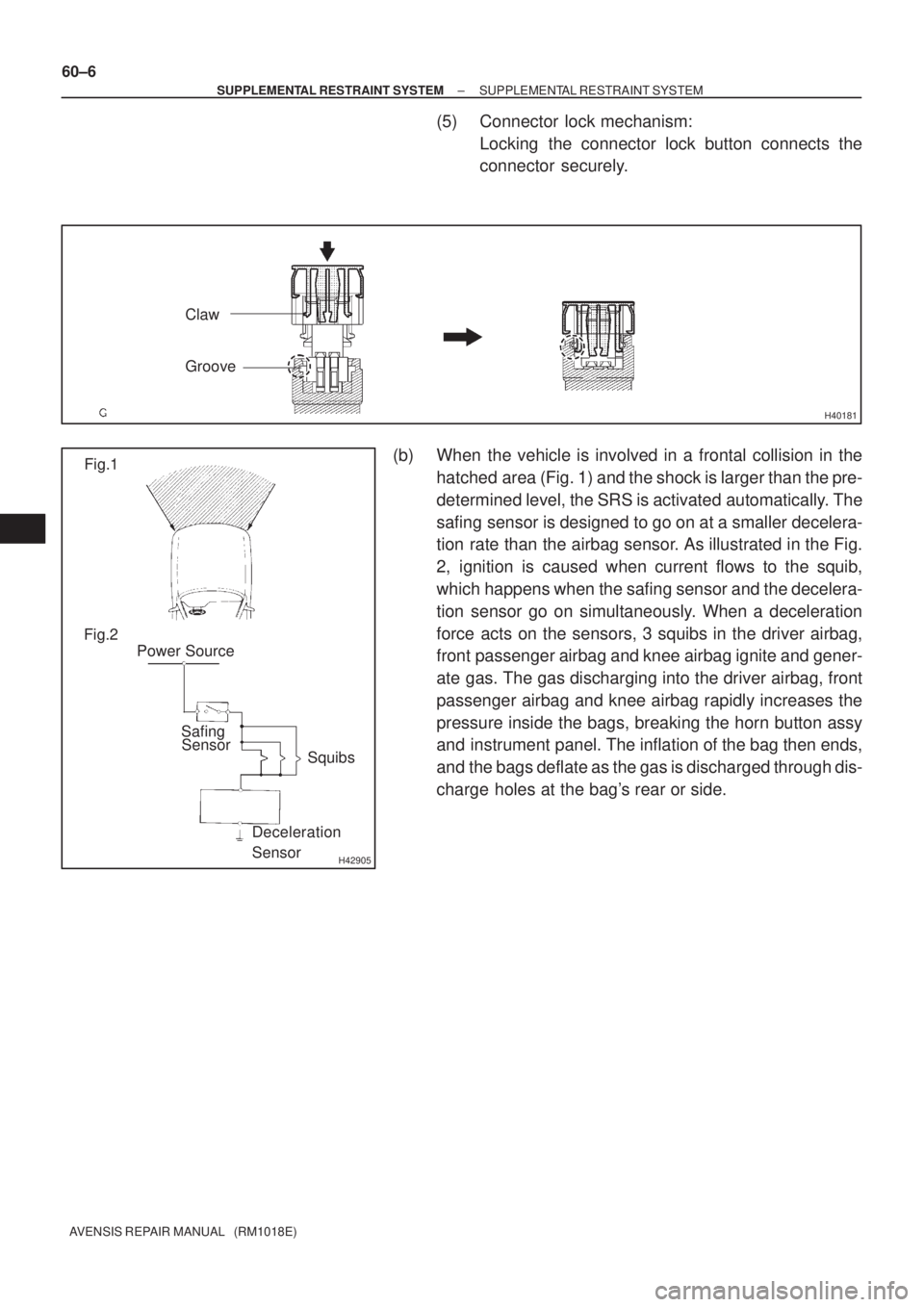
(5) Connector lock mechanism:
Locking the connector lock button connects the
connector securely.
(b) When the vehicle is involved in a frontal collision in the
hatched area (Fig. 1) and the shock is larger than the pre-
determined level, the SRS is activated automatically. The
safing sensor is designed to go on at a smaller decelera-
tion rate than the airbag sensor. As illustrated in the Fig.
2, ignition is caused when current flows to the squib,
which happens when the safing sensor and the decelera-
tion sensor go on simultaneously. When a deceleration
force acts on the sensors, 3 squibs in the driver airbag,
front passenger airbag and knee airbag ignite and gener-
ate gas. The gas discharging into the driver airbag, front
passenger airbag and knee airbag rapidly increases the
pressure inside the bags, breaking the horn button assy
and instrument panel. The inflation of the bag then ends,
and the bags deflate as the gas is discharged through dis-
charge holes at the bag's rear or side.
Page 3103 of 5135
650SY±01
I35230
±
LIGHTING FOG LAMP ASSY LH
65±23
AVENSIS REPAIR MANUAL (RM1018E)
ADJUSTMENT
1.PUT VEHICLE THESE CONDITIONS
(a)Tire inflation pressure is within the specified value. (See page 28±1)
(b) Start the engine.
2. ADJUST FOG LIGHT AIM
(a) The fog light aim can be adjusted by turning the aimingscrew in the vertical direction.
HINT:
The optical aim moves upward when turning the screwdriver
clockwise and moves downward when turning the screwdriver
center clockwise.
3. CHECK FOG LIGHT AIM
Page 3106 of 5135

650SV±01
I33423
V LH LineV RH LineV Line
Ground
H Line
± LIGHTINGHEADLAMP UNIT LH
65±19
AVENSIS REPAIR MANUAL (RM1018E)
ADJUSTMENT
1. HEADLIGHT AIM ONLY
HINT:
�Perform aiming adjustment with Low±beam.
�Since the Low±beam light and the High±beam light is a
unit, if aiming on either side is connect, the other side
should also be connect.
However, check both beams just to make sure.
(a) Prepare vehicle in the following conditions.
�Check that any damage or deformation does not exist on
the body around the headlights.
�Fuel tank is full.
�The tire inflation pressure is at the specified level.
�Vehicle is parked at a level surface.
�A person having an average weight sits in the driver's
seat.
�Vehicle is bounced up and down to stabilize the suspen-
sion to the normal position.
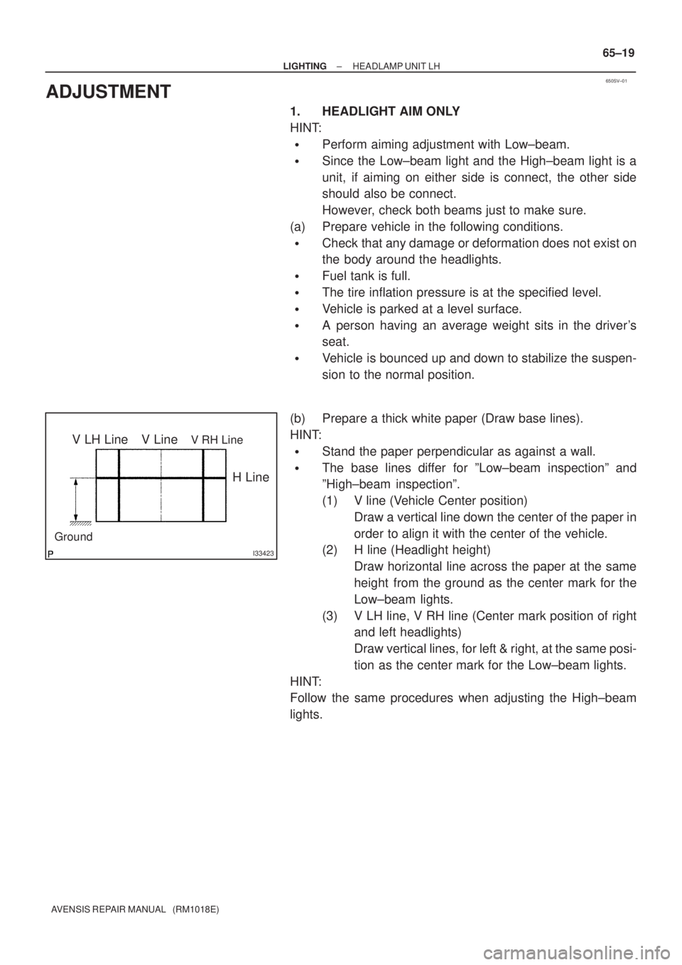
(b) Prepare a thick white paper (Draw base lines).
HINT:
�Stand the paper perpendicular as against a wall.
�The base lines differ for ºLow±beam inspectionº and
ºHigh±beam inspectionº.
(1) V line (Vehicle Center position)
Draw a vertical line down the center of the paper in
order to align it with the center of the vehicle.
(2) H line (Headlight height)
Draw horizontal line across the paper at the same
height from the ground as the center mark for the
Low±beam lights.
(3) V LH line, V RH line (Center mark position of right
and left headlights)
Draw vertical lines, for left & right, at the same posi-
tion as the center mark for the Low±beam lights.
HINT:
Follow the same procedures when adjusting the High±beam
lights.
Page 4125 of 5135
0313C−07
− SERVICE SPECIFICATIONSTIRE & WHEEL
03−29
AVENSIS Supplement (RM1045E)
TIRE & WHEEL
SERVICE DATA
Engine type:
2AZ−FSE
Tire sizeFront
kPa (kgf/cm2, psi)
Rear
kPa (kgf/cm2, psi)
Cold tire inflation pressure
205/55R16 91V:
with 4 or less occupants
with 5 or more occupants
215/45R17 87W:
with 4 or less occupants
with 5 or more occupants220 (2.2, 32)*1
250 (2.5, 36)*2
220 (2.2, 32)*1
270 (2.7, 39)*2
240 (2.4, 35)*1
290 (2.9, 42)*2
240 (2.4, 35)*1
310 (3.1, 45)*2
220 (2.2, 32)*1
250 (2.5, 36)*2
220 (2.2, 32)*1
280 (2.8, 41)*2
240 (2.4, 35)*1
290 (2.9, 42)*2
240 (2.4, 35)*1
330 (3.3, 48)*2
Tire runout1.4 mm (0.055 in.) or less
Imbalance after adjustment8.0 g (0.018 lb) or less
*1: For driving under160 km/h (100 mph)
*2: For driving at160 km/h (100 mph) or over