Page 16 of 5135

010B8±08
D25086
WRONG
CORRECT
D25087
Looseness of Crimping
Core Wire
Terminal
Deformation
Pull Lightly 01±32
± INTRODUCTIONHOW TO TROUBLESHOOT ECU CONTROLLED
SYSTEMS
AVENSIS REPAIR MANUAL (RM1018E)
ELECTRONIC CIRCUIT INSPECTION PROCEDURE
1. BASIC INSPECTION
(a) RESISTANCE MEASURING CONDITION OF ELECTRONIC PARTS
(1) Unless stated, all resistance is measured at an ambient temperature of 20�C (68�F). As the re-
sistance may be outside the specifications if measured at high temperatures immediately after
the vehicle has been running, measurements should be made when the engine has cooled
down.
(b) HANDLING OF CONNECTOR
(1) When removing the connector with lock, press the
connector in the direction of the engagement and
remove the lock by lightly pressing the lock claw.
(2) When removing the connector, do not hold the har-
ness, but hold the connector.
(3) Before connecting the connector, check that there
is no deformation, damage or missing terminals.
(4) The connector with a lock should be securely con-
nected until it makes a ºclickº sound.
(5) When checking the connector with a Toyota electri-
cal tester, check it from the backside (harness side)
of the connector using a mini test lead.
NOTICE:
�As a water proof connector cannot be checked from
the backside, check by connecting the sub±harness.
�Do not damage the terminals by moving the inserted
tester needle.
(c) CONNECTOR CHECKING POINTS
(1) Checking when the connector is connected:
By holding the connector, check the inserted condi-
tion and locking efficiency (engaged condition).
(2) Checking when the connector is removed:
Check by lightly pulling the wire harness (missing
terminal, terminal crimping condition, core wire
break).
Check visually for any rust, metal particles, water
and bent terminals (rust, mixing of foreign object,
terminal deformation).
NOTICE:
When testing a gold±plated female terminal, always use a
gold±plated male terminal.
Page 80 of 5135
022KP±01
02±62
± PREPARATIONEXTERIOR/INTERIOR TRIM
AVENSIS REPAIR MANUAL (RM1018E)
EXTERIOR/INTERIOR TRIM
PREPARATION
Recomended Tools
09070±20010Moulding RemoverFRONT DOOR BELT MOULDING
ASSY LH
REAR DOOR BELT MOULDING
ASSY LH
ROOF HEADLINING
ASSY(LIFTBACK MODELS)
ROOF HEADLINING ASSY(SEDAN
MODELS)
ROOF HEADLINING ASSY(WAGON
MODELS)
Equipment
Adhesive tapeTo avoid surface damage.
Clip remover
Piano wire
Protective tapeTo avoid surface damage.
Torque wrench
Wooden blockFor tying both piano wire ends
Page 82 of 5135
022KO±01
02±60
± PREPARATIONSLIDING ROOF/CONVERTIBLE
AVENSIS REPAIR MANUAL (RM1018E)
SLIDING ROOF/CONVERTIBLE
PREPARATION
Recomended Tools
09041±00020Torx Driver T25SLIDING ROOF
09082±00040TOYOTA Electrical TesterSLIDING ROOF SYSTEM
Equipment
Torque wrench
Page 200 of 5135
031GX±01
03±72
± SERVICE SPECIFICATIONSSLIDING ROOF/CONVERTIBLE
AVENSIS REPAIR MANUAL (RM1018E)
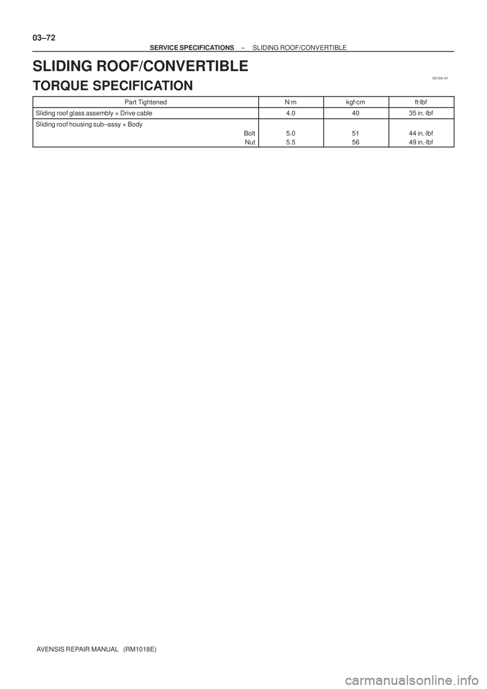
SLIDING ROOF/CONVERTIBLE
TORQUE SPECIFICATION
Part TightenedN�mkgf�cmft�lbf
Sliding roof glass assembly�Drive cable4.04035 in.�lbf
Sliding roof housing sub±assy�Body
Bolt
Nut
5.0
5.551
5644 in.�lbf
49 in.�lbf
Page 2984 of 5135

5. FRONT SEAT AIRBAG ASSY (VEHICLE NOT IN-
VOLVED IN COLLISIO")
H42654
H41401
H42655
H42759
H42656
±
SUPPLEMENTAL RESTRAINT SYSTEM SUPPLEMENTAL RESTRAINT SYSTEM
60±13
AVENSIS REPAIR MANUAL (RM1018E)
5. FRONT SEAT AIRBAG ASSY (VEHICLE NOT IN-
VOLVED IN COLLISION)
(a)Do a diagnostic system check (See page 05±1184).
(b) Do a visual check which includes the following items with
the front seat airbag assy installed in the vehicle:
Cuts, minute cracks or marked discoloration on the front
seat back assy around the front seat airbag assy.
6. FRONT SEAT AIRBAG ASSY (VEHICLE INVOLVED IN COLLISION AND AIRBAG IS NOT DEPLOYED)
(a)Do a diagnostic system check (See page 05±1184).
(b) Do a visual check which includes the following items with the front seat airbag assy removed from the vehicle:
�Cuts, minute cracks or marked discoloration on the
front seat airbag assy.
�Cuts and cracks in wire harness, and chipping in
connectors.
7. CURTAIN SHIELD AIRBAG ASSY (VEHICLE NOT IN- VOLVED IN COLLISION)
(a)Do a diagnostic system check (See page 05±1184).
(b) Do a visual check of the curtain shield airbag assy installed in the vehicle:
Cuts, minute cracks or marked discoloration on the front
pillar garnish and roof headlining assy around the curtain
shield airbag assy.
8. CURTAIN SHIELD AIRBAG ASSY (VEHICLE IN- VOLVED IN COLLISION AND AIRBAG IS NOT
DEPLOYED)
(a)Do a diagnostic system check (See page 05±1184).
(b) Do a visual check which includes the following items with
the curtain shield airbag assy removed from the vehicle:
�Cuts, minute cracks or marked discoloration on the
curtain shield airbag assy.
�Cuts and cracks in wire harness, and chipping in the
connectors.
9. INSTRUMENT PANEL AIRBAG ASSY (VEHICLE IN- VOLVED IN COLLISION)
(a)Do a diagnostic system check (See page 05±1184).
(b) Do a visual check of the instrument panel airbag assy
installed in the vehicle:
Cuts, minute cracks of marked discoloration on the instru-
ment panel airbag assy.
Page 3016 of 5135

REPLACEMENT
1.PRECAUTION (See page 60±1)
2.DISCONNECT BATTERY NEGATIVE TERMINAL (")
600A1±04
H42701
60±62
±
SUPPLEMENTAL RESTRAINT SYSTEM AIR BAG SENSOR ASSY CENTER
AVENSIS REPAIR MANUAL (RM1018E)
REPLACEMENT
1.PRECAUTION (See page 60±1)
2.DISCONNECT BATTERY NEGATIVE TERMINAL (See page 60±1)
3.REMOVE SHIFT LEVER KNOB SUB±ASSY (M/T TRANSAXLE) (See page 71±11)
4.REMOVE CONSOLE PANEL SUB±ASSY UPPER (See page 71±11)
5.REMOVE CONSOLE PANEL SUB±ASSY LOWER (See page 71±11)
6.REMOVE CONSOLE BOX ASSY RR (See page 71±11)
7.REMOVE AIR DUCT REAR NO.3 (See page 71±11)
8.REMOVE AIR DUCT REAR NO.4 (See page 71±11) 9. REMOVE AIR BAG SENSOR ASSY CENTER
(a) Disconnect the 3 connectors from the airbag sensor assycenter.
(b) Remove the 3 bolts and airbag sensor assy center.
10. INSTALL AIR BAG SENSOR ASSY CENTER
(a) Check that the ignition switch is off.
(b) Check that the battery negative (±) terminal is disconnected.
NOTICE:
Do not start the operation for 90 seconds after removing the terminal.
(c) Temporarily install the airbag sensor assy center with the 3 bolts.
NOTICE:
�If the airbag sensor assy center has been dropped, or there are any crac\
ks, dents or other de-
fects in the case, bracket or connector, replace the airbag sensor assy center with a new one.
�When installing the airbag sensor assy center, take care that the SRS wiring does not interfere
with other parts and is not pinched between other parts.
(d) Tighten the 3 bolts to the specified torque. Torque: 17.5 N �m (178 kgf �cm, 13 ft �lbf)
(e) Connect the connectors to the airbag sensor assy center.
(f) Check that no play is identified.
(g) Check that the water±proof sheet is properly set.
11.INSPECT SRS WARNING LIGHT (See page 05±1184)
Page 3032 of 5135

H40005
Battery
SST(s)
±
SUPPLEMENTAL RESTRAINT SYSTEM CURTAIN SHIELD AIR BAG ASSY LH
60±41
AVENSIS REPAIR MANUAL (RM1018E)
DISPOSAL
HINT:
�Disposal procedure of the RH side")
6009Y±02
H40004
SST(s)
H40005
Battery
SST(s)
±
SUPPLEMENTAL RESTRAINT SYSTEM CURTAIN SHIELD AIR BAG ASSY LH
60±41
AVENSIS REPAIR MANUAL (RM1018E)
DISPOSAL
HINT:
�Disposal procedure of the RH side is the same as that for the LH side.
�When scrapping a vehicle equipped with SRS or disposing of the curtain shield airbag assy LH, be sure
to deploy the airbag first in accordance with the procedure described belo\
w. If any abnormality occurs
with the airbag deployment, contact the SERVICE DEPT. of TOYOTA MOTOR SALES, U.S.A., INC.
CAUTION:
�Never dispose of the curtain shield airbag assy LH
that has an undeployed airbag.
�The airbag produces an exploding sound when it is
deployed, so perform the operation outdoors and
where it will not create a nuisance to nearby resi-
dents.
�When deploying the airbag, always use the specified
SST(s) (SRS Airbag Deployment Tool). Perform the
operation in a place away from electrical noise.
�When deploying the airbag, perform the operation at
least 10 m (33 ft) away from the curtain shield airbag
assy LH.
�The curtain shield airbag assy LH is extremely hot
when the airbag is deployed, so do not touch it for at
least 30 minutes after deployment.
�Use gloves and safety glasses when handling the cur-
tain shield airbag assy LH with the deployed airbag.
�Do not apply water, etc. to the curtain shield airbag
assy LH with the deployed airbag.
�Always wash your hands with water after completing
the operation.
1. DISPOSE OF CURTAIN SHIELD AIR BAG ASSY LH (WHEN SCRAPPING VEHICLE DEPLOYMENT
METHOD)
HINT:
Prepare a battery as the power source to deploy the airbag.
(a)Check the function of the SST(s) (See step 1±(a) on page
60±17).
(b) Disconnect the airbag connector.
(1) Sedan Models:Remove the roof headlining assy (See page
76±36).
(2) Liftback Models: Remove the roof headlining assy (See page
76±45).
(3) Wagon Models: Remove the roof headlining assy (See page
76±54).
(4) Using a screwdriver, disconnect the curtain shield airbag LH connector.
Page 3038 of 5135
600K1±01
H43005
H42755
Sedan/Liftback Models:
A
B
C
E
D F
G
60±38
±
SUPPLEMENTAL RESTRAINT SYSTEM CURTAIN SHIELD AIR BAG ASSY LH
AVENSIS REPAIR MANUAL (RM1018E)
REPLACEMENT
HINT:
Replacement procedure of the RH side is the same as that for with LH side.
1.PRECAUTION (See page 60±1)
2.DISCONNECT BATTERY NEGATIVE TERMINAL (See page 60±1)
3.REMOVE ROOF HEADLINING ASSY (SEDAN MODELS) (See page 76±36)
4.REMOVE ROOF HEADLINING ASSY (LIFTBACK MODELS) (See page 76±45)
5.REMOVE ROOF HEADLINING ASSY (WAGON MODELS) (See page 76±54) 6. REMOVE CURTAIN SHIELD AIR BAG ASSY LH(SEDAN/LIFTBACK MODELS)
(a) Using a screwdriver, disconnect the connector of the cur- tain shield airbag assy LH.
(b) After removing the 4 screws and the 3 bolts in order as fol- lows, remove the curtain shield airbag assy LH.
A � B � C � D � E � F � G

EXTERIOR/INTERIOR TRIM
PREPARATION
Recomended Tools
09070±20010Moulding RemoverFRONT DOOR BELT MOULDING
ASSY")

SLIDING ROOF/CONVERTIBLE
PREPARATION
Recomended Tools
09041±00020Torx Driver T25SLIDING ROOF
09082±00040TOYO")

REPLACEMENT
HINT:
Replacement pro")