Page 61 of 5135
022K9±01
02±20
± PREPARATIONLUBRICATION
AVENSIS REPAIR MANUAL (RM1018E)
LUBRICATION
PREPARATION
SST
09023±12900Union Nut Wrench 19mmOIL PUMP ASSY(1AZ±FSE)
09032±00100Oil Pan Seal CutterOIL PUMP ASSY(1AZ±FE)
OIL PUMP ASSY(1AZ±FSE)
OIL PUMP ASSY(1CD±FTV)
09213±54015Crankshaft Pulley Holding ToolOIL PUMP ASSY(1AZ±FE)
OIL PUMP ASSY(1AZ±FSE)
OIL PUMP ASSY(1CD±FTV)
(90105±08076)BoltOIL PUMP ASSY(1CD±FTV)
(91651±60855)BoltOIL PUMP ASSY(1AZ±FE)
OIL PUMP ASSY(1AZ±FSE)
09223±46011Crankshaft Front Oil Seal
ReplacerOIL PUMP ASSY(1CD±FTV)
09228±06501Oil Filter WrenchOIL FILTER SUB±ASSY(1AZ±FE)
OIL FILTER SUB±ASSY(1AZ±FSE)
OIL FILTER
SUB±ASSY(1ZZ±FE/3ZZ±FE)
09228±10002Oil Filter WrenchOIL FILTER SUB±ASSY(1CD±FTV)
09249±63010Torque Wrench AdaptorOIL PUMP ASSY(1AZ±FE)
OIL PUMP ASSY(1AZ±FSE)
09316±60011Transmission & Transfer Bearing
ReplacerOIL PUMP ASSY(1CD±FTV)
(09316±00011)Replacer PipeOIL PUMP ASSY(1CD±FTV)
(09316±00021)Replacer ºAºOIL PUMP ASSY(1CD±FTV)
Page 63 of 5135

02±22
± PREPARATIONLUBRICATION
AVENSIS REPAIR MANUAL (RM1018E)
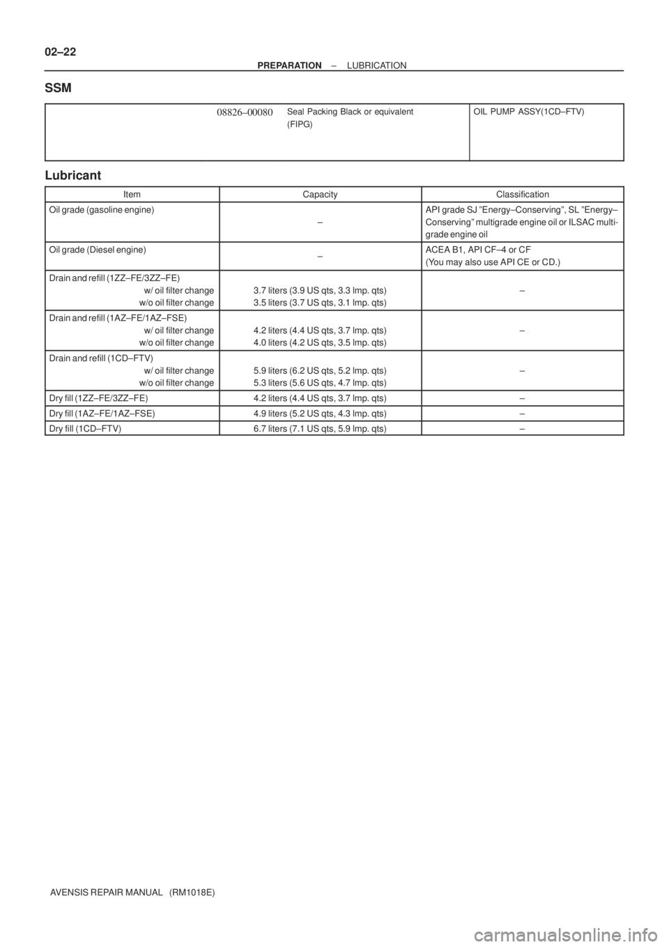
SSM
08826±00080Seal Packing Black or equivalent
(FIPG)OIL PUMP ASSY(1CD±FTV)
Lubricant
ItemCapacityClassification
Oil grade (gasoline engine)
±
API grade SJ ºEnergy±Conservingº, SL ºEnergy±
Conservingº multigrade engine oil or ILSAC multi-
grade engine oil
Oil grade (Diesel engine)±ACEA B1, API CF±4 or CF
(You may also use API CE or CD.)
Drain and refill (1ZZ±FE/3ZZ±FE)
w/ oil filter change
w/o oil filter change
3.7 liters (3.9 US qts, 3.3 lmp. qts)
3.5 liters (3.7 US qts, 3.1 lmp. qts)±
Drain and refill (1AZ±FE/1AZ±FSE)
w/ oil filter change
w/o oil filter change
4.2 liters (4.4 US qts, 3.7 lmp. qts)
4.0 liters (4.2 US qts, 3.5 lmp. qts)±
Drain and refill (1CD±FTV)
w/ oil filter change
w/o oil filter change
5.9 liters (6.2 US qts, 5.2 lmp. qts)
5.3 liters (5.6 US qts, 4.7 lmp. qts)±
Dry fill (1ZZ±FE/3ZZ±FE)4.2 liters (4.4 US qts, 3.7 lmp. qts)±
Dry fill (1AZ±FE/1AZ±FSE)4.9 liters (5.2 US qts, 4.3 lmp. qts)±
Dry fill (1CD±FTV)6.7 liters (7.1 US qts, 5.9 lmp. qts)±
Page 118 of 5135

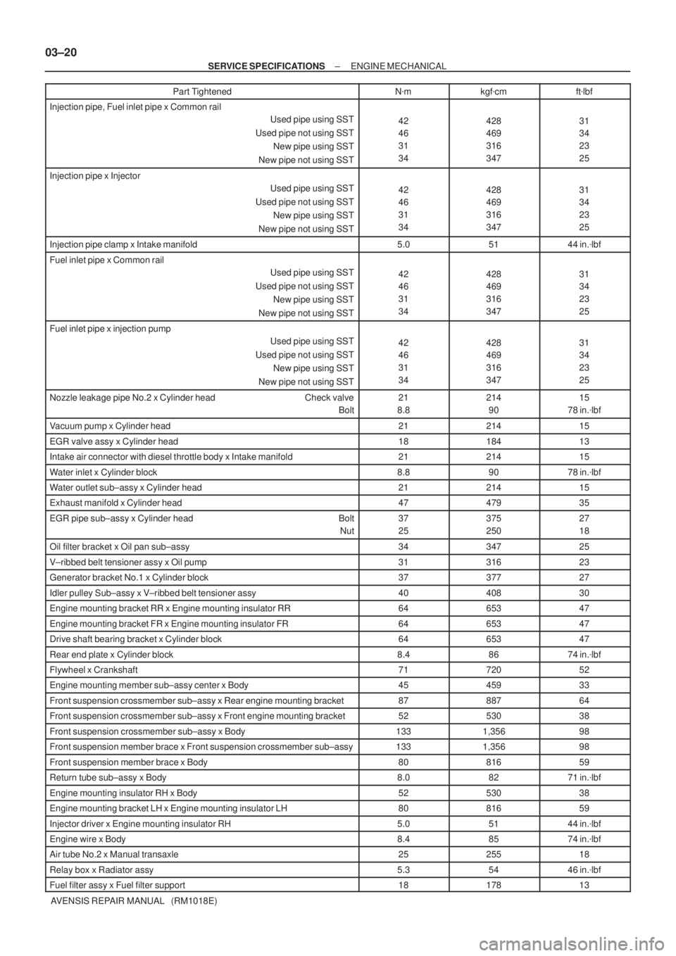
03±20
± SERVICE SPECIFICATIONSENGINE MECHANICAL
AVENSIS REPAIR MANUAL (RM1018E)Part Tightenedft�lbf kgf�cm N�m
Injection pipe, Fuel inlet pipe x Common rail
Used pipe using SST
Used pipe not using SST
New pipe using SST
New pipe not using SST
42
46
31
34428
469
316
34731
34
23
25
Injection pipe x Injector
Used pipe using SST
Used pipe not using SST
New pipe using SST
New pipe not using SST
42
46
31
34428
469
316
34731
34
23
25
Injection pipe clamp x Intake manifold5.05144 in.�lbf
Fuel inlet pipe x Common rail
Used pipe using SST
Used pipe not using SST
New pipe using SST
New pipe not using SST
42
46
31
34428
469
316
34731
34
23
25
Fuel inlet pipe x injection pump
Used pipe using SST
Used pipe not using SST
New pipe using SST
New pipe not using SST
42
46
31
34428
469
316
34731
34
23
25
Nozzle leakage pipe No.2 x Cylinder head Check valve
Bolt21
8.8214
9015
78 in.�lbf
Vacuum pump x Cylinder head2121415
EGR valve assy x Cylinder head1818413
Intake air connector with diesel throttle body x Intake manifold2121415
Water inlet x Cylinder block8.89078 in.�lbf
Water outlet sub±assy x Cylinder head2121415
Exhaust manifold x Cylinder head4747935
EGR pipe sub±assy x Cylinder head Bolt
Nut37
25375
25027
18
Oil filter bracket x Oil pan sub±assy3434725
V±ribbed belt tensioner assy x Oil pump3131623
Generator bracket No.1 x Cylinder block3737727
Idler pulley Sub±assy x V±ribbed belt tensioner assy4040830
Engine mounting bracket RR x Engine mounting insulator RR6465347
Engine mounting bracket FR x Engine mounting insulator FR6465347
Drive shaft bearing bracket x Cylinder block6465347
Rear end plate x Cylinder block8.48674 in.�lbf
Flywheel x Crankshaft7172052
Engine mounting member sub±assy center x Body4545933
Front suspension crossmember sub±assy x Rear engine mounting bracket8788764
Front suspension crossmember sub±assy x Front engine mounting bracket5253038
Front suspension crossmember sub±assy x Body1331,35698
Front suspension member brace x Front suspension crossmember sub±assy1331,35698
Front suspension member brace x Body8081659
Return tube sub±assy x Body8.08271 in.�lbf
Engine mounting insulator RH x Body5253038
Engine mounting bracket LH x Engine mounting insulator LH8081659
Injector driver x Engine mounting insulator RH5.05144 in.�lbf
Engine wire x Body8.48574 in.�lbf
Air tube No.2 x Manual transaxle2525518
Relay box x Radiator assy5.35446 in.�lbf
Fuel filter assy x Fuel filter support1817813
Page 259 of 5135

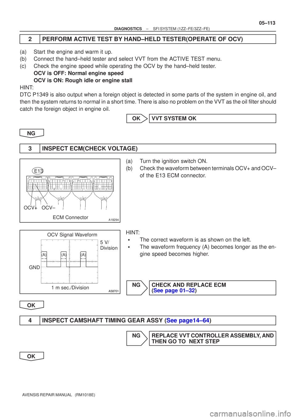
A18294
OCV+OCV±
ECM Connector
E13
A58701A58701
OCV Signal Waveform1 m sec./Division 5 V/
Division
GND
(A)(A)(A)
±
DIAGNOSTICS SFI SYSTEM(1ZZ±FE/3ZZ±FE)
05±113
AVENSIS REPAIR MANUAL (RM1018E)
2PERFORM ACTIVE TEST BY HAND±HELD TESTER(OPERATE OF OCV)
(a)Start the engine and warm it up.
(b)Connect the hand±held tester and select VVT from the ACTIVE TEST menu\
.
(c)Check the engine speed while operating the OCV by the hand±held teste\
r.
OCV is OFF: Normal engine speed
OCV is ON: Rough idle or engine stall
HINT:
DTC P1349 is also output when a foreign object is detected in some parts\
of the system in engine oil, and
then the system returns to normal in a short time. There is also no problem \
on the VVT as the oil filter should
catch the foreign object in engine oil.
OKVVT SYSTEM OK
NG
3INSPECT ECM(CHECK VOLTAGE)
(a)Turn the ignition switch ON.
(b)Check the waveform between terminals OCV+ and OCV± of the E13 ECM connector.
HINT:
�The correct waveform is as shown on the left.
�The waveform frequency (A) becomes longer as the en-
gine speed becomes higher.
NGCHECK AND REPLACE ECM (See page 01±32)
OK
4INSPECT CAMSHAFT TIMING GEAR ASSY (See page14±64)
NG REPLACE VVT CONTROLLER ASSEMBLY, AND THEN GO TO NEXT STEP
OK
Page 260 of 5135
05±114
±
DIAGNOSTICS SFI SYSTEM(1ZZ±FE/3ZZ±FE)
AVENSIS REPAIR MANUAL (RM1018E)
5INSPECT CAMSHAFT TIMING OIL CONTROL VALVE ASSY (See page 10±3)
NGREPLACE CAMSHAFT TIMING OIL CONTROL VALVE ASSEMBLY, AND THEN GO TO NEXT
STEP
OK
6CHECK OIL CONTROL VALVE FILTER(CHECK BLOCKAGE)
NGREPAIR OR REPLACE OIL CONTROL VALVE FILTER
OK
7PERFORM SIMULATION TEST(DTC CHECK)
(a)Clear the DTC (See page 05±5).
(b)Perform the simulation test.
(c)Check whether or not DTC P1349 is stored (See page 05±5). Result:
DTCProceed to
ºP1349º is output.A
ºP1349º is not output.B
HINT:
DTC P1349 is also output when a foreign object is detected in some parts\
of the system in engine oil, and
then the system returns to normal in a short time. There is also no problem \
on the VVT as the oil filter should
catch the foreign object in the engine oil.
BVVT SYSTEM OK
A
CHECK AND REPLACE ECM (See page 01±32)
Page 263 of 5135
������A79093
ECM
EH W±B E13
IGT1
IGF
E13
E13
E13
E13 23 IGT2
IGT3
IGT4
8
10
11
R±W
3
2
1
I1
Ignition Coil and
Igniter No.1
I2
Ignition Coil and
Igniter No.2
I3
Ignition Coil and
Igniter No.3
I4
Ignition Coil and
Igniter No.4
R±B
W±B 4 3
2
B±R
1
1
1
B±R
R±B
33
2
2
L±YW±R
W±R W±R
4 4 4
W±B
W±B
W±B
W±B
R±B
W±R
R±B R±B
From Terminal 3
of IG2 Relay
(See Page 05±124)
W±B LG±B
P
W±R
W±R
W±R 9
R±B 1N2
Noise
Filter R±B
8 EA1
±
DIAGNOSTICS SFI SYSTEM (1ZZ±FE/3ZZ±FE)
05±105
AVENSIS REPAIR MANUAL (RM1018E)
WIRING DIAGRAM
Page 404 of 5135
A76873
8
IGF IGT2 IGT1
IGT3 E13
IGT4 I1
Ignition Coil and
Igniter No. 1
P R±W
IGNW±R IE4
LG±B
ECR±B
L±YE13
E13
E13
E139
1110
13 I2
Ignition Coil and
Igniter No. 2
I3
Ignition Coil and
Igniter No. 3
I4
Ignition Coil and
Igniter No. 4W±R
W±RW±R 3
2
14
1
42
2 3
3
3 1
4
4 1 R±B R±B
R±B R±B R±B B±R
W±B
W±B
W±B
W±BW±B W±BW±B
1
N2
Noise Filter
(Ignition)R±B B±R 1
3 Engine Room R/B No. 1 and
Engine Room J/B No.1
B±G 1A
2
B±G
FL MAIN
Battery Engine Room
J/B No.4I13
Ignition Switch
6
AM2 IG24
(LHD)IP11
(RHD)
B±R
1
1
1 1 2
2 AM2IG2
1B±R
BB
5144
44DH 2
DL 16
IG2
Relay
4A 1
4B 1Engine
Room
R/B No.4
EA1
8R±B
R±BW±B
EF B±R2ECM
W±R
W±R Driver
Side J/B 05±234
± DIAGNOSTICSSFI SYSTEM (1AZ±FE)
AVENSIS REPAIR MANUAL (RM1018E)
WIRING DIAGRAM
Page 439 of 5135

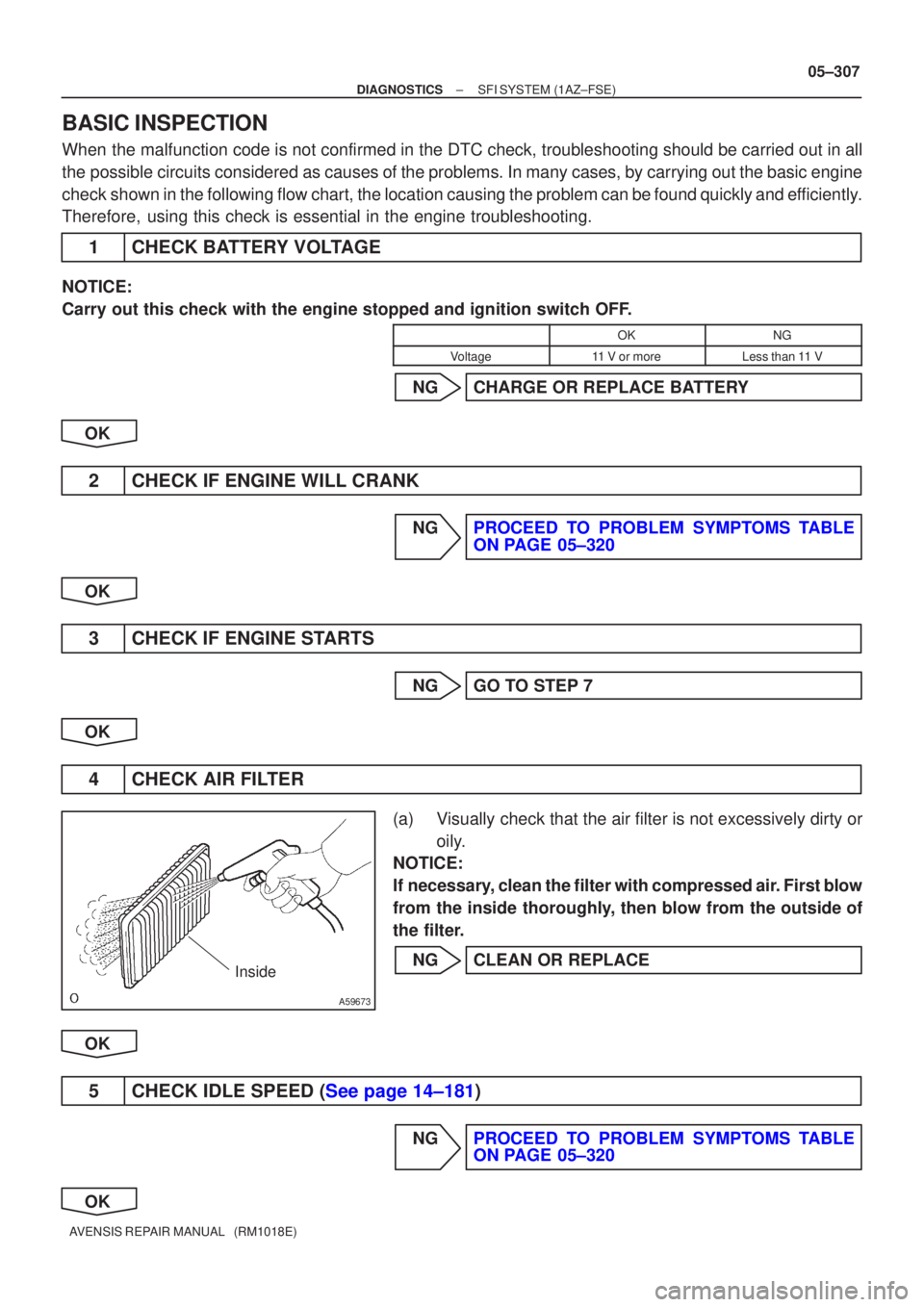
A59673
Inside
±
DIAGNOSTICS SFI SYSTEM(1AZ±FSE)
05±307
AVENSIS REPAIR MANUAL (RM1018E)
BASIC INSPECTION
When the malfunction code is not confirmed in the DTC check, troubleshooting should be carried out in all
the possible circuits considered as causes of the problems. In many cases, by carrying out the basic engi\
ne
check shown in the following flow chart, the location causing the problem can be found quickly and efficiently.
Therefore, using this check is essential in the engine troubleshooting.
1CHECK BATTERY VOLTAGE
NOTICE:
Carry out this check with the engine stopped and ignition switch OFF.
OKNG
Voltage11 V or moreLess than 11 V
NGCHARGE OR REPLACE BATTERY
OK
2CHECK IF ENGINE WILL CRANK
NGPROCEED TO PROBLEM SYMPTOMS TABLE ON PAGE 05±320
OK
3CHECK IF ENGINE STARTS
NGGO TO STEP 7
OK
4CHECK AIR FILTER
(a)Visually check that the air filter is not excessively dirty or oily.
NOTICE:
If necessary, clean the filter with compressed air. First blow
from the inside thoroughly, then blow from the outside of
the filter.
NGCLEAN OR REPLACE
OK
5CHECK IDLE SPEED (See page 14±181)
NGPROCEED TO PROBLEM SYMPTOMS TABLE ON PAGE 05±320
OK