Page 8 of 5135

GLOSSARY OF SAE AND TOYOTA TERMS
This glossary lists all SAE±J1930 terms and abbreviations used in this manual in compliance wi")
010BA±14
01±42
± INTRODUCTIONTERMS
AVENSIS REPAIR MANUAL (RM1018E)
GLOSSARY OF SAE AND TOYOTA TERMS
This glossary lists all SAE±J1930 terms and abbreviations used in this manual in compliance with SAE rec-
ommendations, as well as their TOYOTA equivalents.
SAE
ABBREVIATIONSSAE TERMSTOYOTA TERMS
( )±±ABBREVIATIONS
A/CAir ConditioningAir Conditioner
ACLAir CleanerAir Cleaner, A/CL
AIRSecondary Air InjectionAir Injection (AI)
APAccelerator Pedal±
B+Battery Positive Voltage+B, Battery Voltage
BAROBarometric PressureHAC
CACCharge Air CoolerIntercooler
CARBCarburetorCarburetor
CFIContinuous Fuel Injection±
CKPCrankshaft PositionCrank Angle
CLClosed LoopClosed Loop
CMPCamshaft PositionCam Angle
CPPClutch Pedal Position±
CTOXContinuous Trap Oxidizer±
CTPClosed Throttle PositionLL ON, Idle ON
DFIDirect Fuel Injection (Diesel)Direct Injection (DI/INJ)
DIDistributor Ignition±
DLC1
DLC2
DLC3Data Link Connector 1
Data Link Connector 2
Data Link Connector 31: Check Connector
2: Total Diagnosis Communication Link (TDCL)
3: OBD II Diagnostic Connector
DTCDiagnostic Trouble CodeDiagnostic Trouble Code
DTMDiagnostic Test Mode±
ECLEngine Control Level±
ECMEngine Control ModuleEngine ECU (Electronic Control Unit)
ECTEngine Coolant TemperatureCoolant Temperature, Water Temperature (THW)
EEPROMElectrically Erasable Programmable Read Only Memory
Electrically Erasable Programmable Read Only Memory
(EEPROM),
Erasable Programmable Read Only Memory (EPROM)
EFEEarly Fuel EvaporationCold Mixture Heater (CMH), Heat Control Valve (HCV)
EGRExhaust Gas RecirculationExhaust Gas Recirculation (EGR)
EIElectronic IgnitionDistributorless Ignition (DLI)
EMEngine ModificationEngine Modification (EM)
EPROMErasable Programmable Read Only MemoryProgrammable Read Only Memory (PROM)
EVAPEvaporative EmissionEvaporative Emission Control (EVAP)
FCFan Control±
FEEPROMFlash Electrically Erasable Programmable
Read Only Memory±
FEPROMFlash Erasable Programmable Read Only Memory±
FFFlexible Fuel±
FPFuel PumpFuel Pump
GENGeneratorAlternator
GNDGroundGround (GND)
Page 11 of 5135

TERMS
ABBREVIATIONS USED IN THIS MANUAL
AbbreviationsMeaning
ABSAnti±Lock Brake System
A/CAir Conditioner
ACAlternating Current")
010B9±11
± INTRODUCTIONTERMS
01±37
AVENSIS REPAIR MANUAL (RM1018E)
TERMS
ABBREVIATIONS USED IN THIS MANUAL
AbbreviationsMeaning
ABSAnti±Lock Brake System
A/CAir Conditioner
ACAlternating Current
ACCAccessory
ACISAcoustic Control Induction System
ACSDAutomatic Cold Start Device
A.D.D.Automatic Disconnecting Differential
A/FAir±Fuel Ratio
AHCActive Height Control Suspension
ALRAutomatic Locking Retractor
ALTAlternator
AMPAmplifier
ANTAntenna
Approx.Approximately
ASSYAssembly
A/T, ATMAutomatic Transmission (Transaxle)
AT FAutomatic Transmission Fluid
AUTOAutomatic
AUXAuxiliary
AV GAverage
AV SAdaptive Variable Suspension
B+Battery Voltage
BABrake Assist
BACSBoost Altitude Compensation System
BATBattery
BDCBottom Dead Center
B/LBi±Level
B/SBore±Stroke Ratio
BTDCBefore Top Dead Center
BVSVBimetallic Vacuum Switching Valve
CANController Area Network
CBCircuit Breaker
CCoCatalytic Converter For Oxidation
CDCompact Disc
CFCornering Force
CGCenter Of Gravity
CHChannel
CKDComplete Knock Down
COMB.Combination
CPECoupe
CPSCombustion Pressure Sensor
CPUCentral Processing Unit
CRSChild Restraint System
CTRCenter
C/VCheck Valve
CVControl Valve
CWCurb Weight
DCDirect Current
Page 153 of 5135

TORQUE SPECIFICATION
1ZZ±FE/3ZZ±FE:
Part TightenedN�mkgf�cmft�lbf
Starter assy x Transaxle housing3737")
031E7±03
± SERVICE SPECIFICATIONSSTARTING & CHARGING
03±33
AVENSIS REPAIR MANUAL (RM1018E)
TORQUE SPECIFICATION
1ZZ±FE/3ZZ±FE:
Part TightenedN�mkgf�cmft�lbf
Starter assy x Transaxle housing3737828
Starter wire x Starter assy9.81007
Generator assy x Transverse engine engine mounting bracket2525518
Generator assy x Cylinder block sub±assy5455140
Generator wire x Generator assy9.81007
Lead wire of field coil x Terminal C5.96052 in.�lbf
1AZ±FE/1AZ±FSE:
Part TightenedN�mkgf�cmft�lbf
Wire harness clamp bracket x Starter assy8.48674 in.�lbf
Starter assy x Cylinder block sub±assy3738028
Starter wire x Starter assy9.81007
Battery carrier x Body131319
Battery clamp sub±assy x Body5.05144 in.�lbf
Battery clamp sub±assy x Battery clamp bolt3.63631 in.�lbf
Terminal x Battery5.45548 in.�lbf
Wire harness clamp bracket x Generator assy8.48674 in.�lbf
Generator assy x Cylinder block sub±assy Bolt A
Bolt B52
21530
21438
16
Generator wire x Generator assy9.81007
Lead wire of field coil x Terminal C5.96052 in.�lbf
1CD±FTV:
Part TightenedN�mkgf�cmft�lbf
Starter x Transaxle Bolt
Terminal 3037
9.8377
10027
7.2
Generator assy x Engine M8
M10
Alternator wire
Wire harness31
47
9.8
5.0320
475
100
5123
34
7
44 in.�lbf
Glow plug assy x Cylinder head Glow plug
Nut12.3
2.2125
229
19 in.�lbf
Engine cover No. 1 x Cylinder head cover sub±assy8.08271 in.�lbf
Engine cover No. 1 x Intake manifold8.08271 in.�lbf
Front wheel RH1031,05076
Page 1188 of 5135
05C7Z±01
05±1170
±
DIAGNOSTICS COMBUSTION TYPE POWER HEATER SYSTEM
AVENSIS REPAIR MANUAL (RM1018E)
PROBLEM SYMPTOMS TABLE
If the normal code is displayed during DTC check although the problem still occurs, check the circuits for
each problem symptom in the order given in the table below, and proceed to the relevant troubleshooting.
SymptomSuspect AreaSee page
The combustion type power heater does not operate
1. ECU power source circuit
2. Power heater switch circuit
3. Power heater fuel pump circuit
4. Power heater alternator circuit05±1171
05±1173
05±1176
05±1179
Page 1189 of 5135
05C7Y±01
I36138
P1
± DIAGNOSTICSCOMBUSTION TYPE POWER HEATER SYSTEM
05±1169
AVENSIS REPAIR MANUAL (RM1018E)
TERMINALS OF ECU
1. POWER HEATER ECU
Terminal No. (Symbols)Wiring ColorConditionSpecification
P1±1 (±) ± Body groundW±B ± Body groundAlwaysContinuity
P1±2 (F/P) ± Body groundL ± Body groundAlwaysContinuity
P1±3 (SW) ± Body groundG±Y ± Body groundIG SW: ON
Power heater SW: ON10 to 14
P1±5 (+) ± Body groundW ± Body groundAlwaysContinuity
P1±8 (ALT +L ) ± Body groundY ± Body groundAlternator: OperatePulse generation
Page 1190 of 5135
05C7X±01
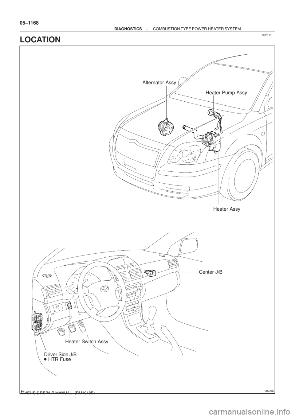
I36096
Heater Pump Assy Alternator Assy
Heater Assy
Center J/B
Heater Switch Assy
Driver Side J/B
� HTR Fuse
05±1168
± DIAGNOSTICSCOMBUSTION TYPE POWER HEATER SYSTEM
AVENSIS REPAIR MANUAL (RM1018E)
LOCATION
Page 1194 of 5135
I35431
Buner Motor
Glow Plug
Surface Sensor
Temp.Control Sensor
Flame Sensor13
Power
Heater
ECU
Connector BTerminal L
of AlternatorBattery
Metering Pump
Fuse (20 A)
Vehicle Side SW 14
9
12
5
6
3
4
1
2BR
G
L±Y
L B±R
Y
L±WR
1
2
3
4 5
6
7
8W±B Connector A
IG
R±G
R±L (*1)
R±Y (*2)
R±B
W±R (*1)
Y±R (*2)
*1: TMC Made
*2: TMUK Made
± DIAGNOSTICSCOMBUSTION TYPE POWER HEATER SYSTEM
05±1165
AVENSIS REPAIR MANUAL (RM1018E)
2. DESCRIPTION OF DISPLAY AND BUTTONS
(a) AF: Current Value Malfunction (Blinking at current failure)
Diag: DTC (Example: 064 Flame sensor break)
Memory Clear button: Deletion of faulty memory (Press both buttons together for longer than 2 sec.)
> Button: Scroll up of faulty memory (The past 5 codes can be stored.)
< Button: Scroll down of faulty memory (The past 5 codes can be stored.)
3. FAULTY MEMORY
(a) The ECU is able to store upto 5 pieces of faulty memory. If it is full, the new data is written over F5.
4. WIRING DIAGRAM
Page 1242 of 5135
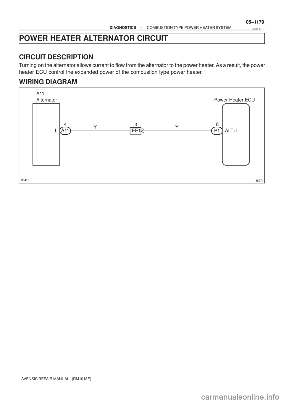
������I35971
A11
AlternatorPower Heater ECU
L EE1
P1ALT+L A114
38
YY
± DIAGNOSTICSCOMBUSTION TYPE POWER HEATER SYSTEM
05±1179
AVENSIS REPAIR MANUAL (RM1018E)
POWER HEATER ALTERNATOR CIRCUIT
CIRCUIT DESCRIPTION
Turning on the alternator allows current to flow from the alternator to the power heater. As a result, the power
heater ECU control the expanded power of the combustion type power heater.
WIRING DIAGRAM
05C83±01

PROBLEM SYMPTOMS TABLE
If the normal code is displayed during DTC check although the problem sti")

TERMINALS OF ECU
1. POWER HEATER ECU
Terminal No. (Symbols)Wiring ColorConditionSpecifi")

Vehicle Side SW 14
9
12
5
6
3
4
1
2")