Page 57 of 5135
± PREPARATIONREAR SUSPENSION
02±27
AVENSIS REPAIR MANUAL (RM1018E)
(09955±04051)Claw No.5REAR SUSPENSION ARM ASSY
NO.1 LH
(09957±04010)AttachmentREAR SUSPENSION ARM ASSY
NO.1 LH
(09958±04011)HolderREAR SUSPENSION ARM ASSY
NO.1 LH
Recomended Tools
09040±00011Hexagon Wrench SetREAR SHOCK ABSORBER WITH
COIL SPRING
REAR SUSPENSION ARM ASSY
NO.1 LH
STABILIZER BAR REAR
(09043±20050)Socket Hexagon Wrench 5REAR SHOCK ABSORBER WITH
COIL SPRING
REAR SUSPENSION ARM ASSY
NO.1 LH
STABILIZER BAR REAR
(09043±20060)Socket Hexagon Wrench 6REAR SHOCK ABSORBER WITH
COIL SPRING
Equipment
Torque wrench
Dial indicator with magnetic base
Wheel balancer
Tire pressure gauge
Alignment tester
Toe±in gauge
Camber±caster±kingpin gauge
Drill
Page 175 of 5135

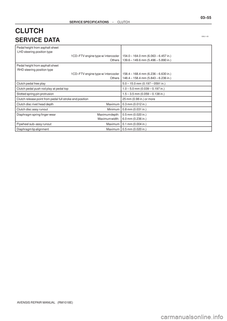
030L1±03
± SERVICE SPECIFICATIONSCLUTCH
03±55
AVENSIS REPAIR MANUAL (RM1018E)
CLUTCH
SERVICE DATA
Pedal height from asphalt sheet
LHD steering position type
1CD±FTV engine type w/ intercooler
Others
154.0 ± 164.0 mm (6.063 ± 6.457 in.)
139.6 ± 149.6 mm (5.496 ± 5.890 in.)
Pedal height from asphalt sheet
RHD steering position type
1CD±FTV engine type w/ intercooler
Others
158.4 ± 168.4 mm (6.236 ± 6.630 in.)
148.4 ± 158.4 mm (5.843 ± 6.236 in.)
Clutch pedal free play5.0 ± 15.0 mm (0.197 ± 0591 in.)
Clutch pedal push rod play at pedal top1.0 ± 5.0 mm (0.039 ± 0.197 in.)
Slotted spring pin protrusion1.5 ± 3.5 mm (0.059 ± 0.138 in.)
Clutch release point from pedal full stroke end position25 mm (0.98 in.) or more
Clutch disc rivet head depth Maximum0.3 mm (0.012 in.)
Clutch disc assy runout Minimum0.8 mm (0.031 in.)
Diaphragm spring finger wear Maximum depth:
Maximum width:0.5 mm (0.020 in.)
6.0 mm (0.236 in.)
Flywheel sub±assy runout Maximum0.1 mm (0.004 in.)
Diaphragm tip alignment Maximum0.5 mm (0.020 in.)
Page 824 of 5135

BR3893
Malfunction Code (Example Code 72 76)
ON
OFF
0.5 sec. 0.5 sec.1.5 sec.
0.5 sec.2.5 sec.
0.5 sec. 72 7 6
4 sec.
Repeat 05±764
± DIAGNOSTICSABS WITH EBD & BA & TRC & VSC SYSTEM
AVENSIS REPAIR MANUAL (RM1018E)
�If 2 or more DTCs are detected at the same time, the low-
est numbered code is displayed first.
(f) After the check, disconnect the SST from terminal Ts and
CG, Tc and CG of DLC3 and turn the ignition switch to
OFF.
SST 09843±19040
6. With using hand±held tester:
ABS SENSOR SIGNAL CHECK (TEST MODE)
NOTICE:
After replacing the steering angle sensor and/or ECU, perform zero point calibration of the steering
angle sensor or system decision (When replacing the ECU) (See step 7.).
HINT:
If the ignition switch is turned from ON to ACC or LOCK during test mode, the DTCs will be erased.
(a) Hook up the hand±held tester to the DLC3.
(b) Perform step 5. (c) to (d) on the previous page.
(c) Read the DTC by following the prompts on the tester screen.
HINT:
Please refer to the hand±held tester operator's manual for further details.
7. STEERING ANGLE SENSOR ZERO POINT CALIBRATION
NOTICE:
When replacing the steering angle sensor with column assembly or ECU, Engine and ECT ECU (A/T),
Engine ECU (M/T) or when adjusting the front wheel alignment or steering wheel center point in ac-
cordance with the removing or installing or replacing the suspension, axle or steering parts, make
sure to perform steering angle sensor zero point calibration.
(a) Using SST, connect terminals Ts and CG of the DLC3
.
SST 09843±18040
(b) Turn the ignition switch ON and keep the shift lever at P range.
(c) Make sure the steering off center angle is less than �3� when assembling the steering wheels (Smaller
value is desirable).
(d) Press the TRC OFF switch and hold it.
(e) Check that the following conditions are satisfied.
HINT:
�Engine warning light comes on.
�ABS warning light is blinking.
(f) Depress the brake pedal 3 times or more within 2 seconds.
Page 1084 of 5135

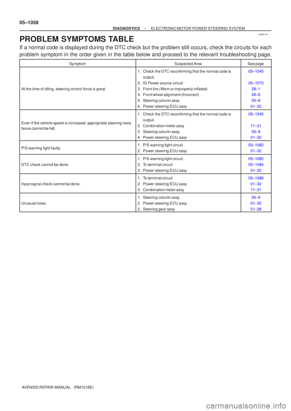
050WP±04
05±1058
±
DIAGNOSTICS ELECTRONIC MOTOR POWER STEERING SYSTEM
AVENSIS REPAIR MANUAL (RM1018E)
PROBLEM SYMPTOMS TABLE
If a normal code is displayed during the DTC check but the problem still o\
ccurs, check the circuits for each
problem symptom in the order given in the table below and proceed to the releva\
nt troubleshooting page.
SymptomSuspected AreaSee page
At the time of idling, steering control force is great.
1. Check the DTC reconfirming that the normal code is output.
2. IG Power source circuit
3. Front tire (Worn or improperly inflated)
4. Front wheel alignment (Incorrect)
5. Steering column assy
6. Power steering ECU assy05±1045
05±1073 28±1
26±6
50±9
01±32
Even if the vehicle speed is increased, appropriate steering resis-
tance cannot be felt.
1. Check the DTC reconfirming that the normal code is output.
2. Combination meter assy
3. Steering column assy
4. Power steering ECU assy05±1045
71±2150±9
01±32
P/S warning light faulty.1. P/S warning light circuit
2. Power steering ECU assy05±1082
01±32
DTC check cannot be done.
1. P/S warning light circuit
2. Tc terminal circuit
3. Power steering ECU assy05±1082
05±108401±32
Input signal check cannot be done.
1. Ts terminal circuit
2. Power steering ECU assy
3. Combination meter assy05±108601±32
71±21
Unusual noise.
1. Steering column assy
2. Power steering ECU assy
3. Steering gear assy50±9
01±32
51±28
Page 2060 of 5135

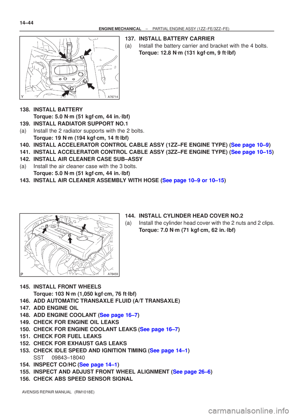
A76714
A78459
14±44
±
ENGINE MECHANICAL PARTIAL ENGINE ASSY (1ZZ±FE/3ZZ±FE)
AVENSIS REPAIR MANUAL (RM1018E)
137. INSTALL BATTERY CARRIER
(a) Install the battery carrier and bracket with the 4 bolts. Torque: 12.8 N �m (131 kgf �cm, 9 ft �lbf)
138. INSTALL BATTERY Torque: 5.0 N �m (51 kgf �cm, 44 in. �lbf)
139. INSTALL RADIATOR SUPPORT NO.1
(a) Install the 2 radiator supports with the 2 bolts. Torque: 19 N �m (194 kgf �cm, 14 ft �lbf)
140.INSTALL ACCELERATOR CONTROL CABLE ASSY (1ZZ±FE ENGINE TYPE) (See page 10±9)
141.INSTALL ACCELERATOR CONTROL CABLE ASSY (3ZZ±FE ENGINE TYPE) (See page 10±15)
142. INSTALL AIR CLEANER CASE SUB±ASSY
(a) Install the air cleaner case with the 3 bolts. Torque: 5.0 N �m (51 kgf �cm, 44 in. �lbf)
143.INSTALL AIR CLEANER ASSEMBLY WITH HOSE (See page 10±9 or 10±15)
144. INSTALL CYLINDER HEAD COVER NO.2
(a) Install the cylinder head cover with the 2 nuts and 2 clips.Torque: 7.0 N �m (71 kgf �cm, 62 in. �lbf)
145. INSTALL FRONT WHEELS Torque: 103 N �m (1,050 kgf �cm, 76 ft �lbf)
146. ADD AUTOMATIC TRANSAXLE FLUID (A/T TRANSAXLE)
147. ADD ENGINE OIL
148.ADD ENGINE COOLANT (See page 16±7)
149. CHECK FOR ENGINE OIL LEAKS
150.CHECK FOR ENGINE COOLANT LEAKS(See page 16±7)
151. CHECK FOR FUEL LEAKS
152. CHECK FOR EXHAUST GAS LEAKS
153.CHECK IDLE SPEED AND IGNITION TIMING(See page 14±1)
SST 09843±18040
154.INSPECT CO/HC(See page 14±1)
155.INSPECT AND ADJUST FRONT WHEEL ALIGNMENT (See page 26±6)
156. CHECK ABS SPEED SENSOR SIGNAL
Page 2082 of 5135
14±134
±
ENGINE MECHANICAL PARTIAL ENGINE ASSY(1AZ±FE)
AVENSIS REPAIR MANUAL (RM1018E)
155.INSTALL RADIATOR ASSY (See page 16±24)
156.INSTALL RADIATOR RELAY BLOCK Torque: 5.0 N �m (51 kgf �cm,44 in. �lbf)
157.INSTALL ENGINE COVER SUB±ASSY NO.1 Torque: 7.0 N �m (71 kgf �cm,62 in. �lbf)
158.ADD MANUAL TRANSAXLE OIL (M/T TRANSAXLE)
159.ADD AUTOMATIC TRANSAXLE FLUID (A/T TRANSAXLE)
160.ADD ENGINE OIL
161.ADD COOLANT (See page 16±19)
162. ADD POWER STEERING FLUID
163. BLEED POWER STEERING FLUID
164. CHECK FOR ENGINE OIL LEAKS
165.CHECK FOR ENGINE COOLANT LEAKS (See page 16±13)
166.CHECK FOR FUEL LEAKS (See page 11±15)
167. INSTALL FRONT WHEELS Torque: 103 N �m (1,050 kgf �cm, 76 ft �lbf)
168.ADJUST FRONT WHEEL ALIGNMENT (See page 26±6)
169.INSPECT CHECK IDLE SPEED AND IGNITION TIMING (See page 14±101)
170.INSPECT CO/HC (See page 14±101)
171. CHECK ABS SPEED SENSOR SIGNAL
Page 2213 of 5135

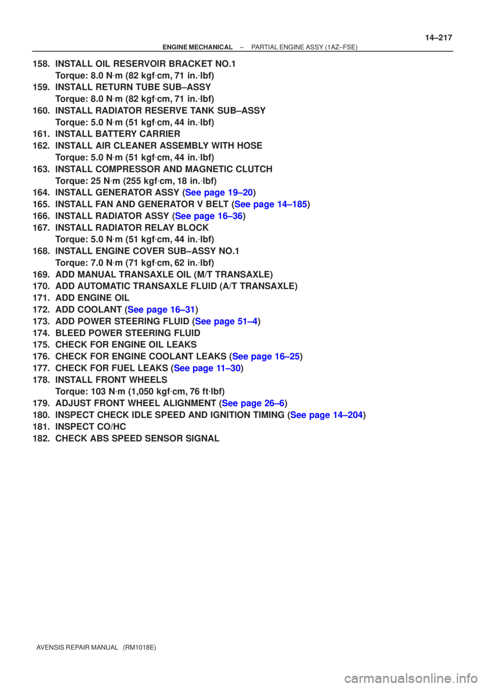
±
ENGINE MECHANICAL PARTIAL ENGINE ASSY(1AZ±FSE)
14±217
AVENSIS REPAIR MANUAL (RM1018E)
158.INSTALL OIL RESERVOIR BRACKET NO.1
Torque: 8.0 N �m (82 kgf �cm,71 in. �lbf)
159.INSTALL RETURN TUBE SUB±ASSY
Torque: 8.0 N �m (82 kgf �cm,71 in. �lbf)
160.INSTALL RADIATOR RESERVE TANK SUB±ASSY Torque: 5.0 N �m (51 kgf �cm,44 in. �lbf)
161.INSTALL BATTERY CARRIER
162.INSTALL AIR CLEANER ASSEMBLY WITH HOSE
Torque: 5.0 N �m (51 kgf �cm,44 in. �lbf)
163.INSTALL COMPRESSOR AND MAGNETIC CLUTCH Torque: 25 N �m (255 kgf �cm,18 in. �lbf)
164.INSTALL GENERATOR ASSY (See page 19±20)
165.INSTALL FAN AND GENERATOR V BELT (See page 14±185)
166.INSTALL RADIATOR ASSY (See page 16±36)
167. INSTALL RADIATOR RELAY BLOCK Torque: 5.0 N �m (51 kgf �cm, 44 in. �lbf)
168. INSTALL ENGINE COVER SUB±ASSY NO.1 Torque: 7.0 N �m (71 kgf �cm, 62 in. �lbf)
169. ADD MANUAL TRANSAXLE OIL (M/T TRANSAXLE)
170. ADD AUTOMATIC TRANSAXLE FLUID (A/T TRANSAXLE)
171. ADD ENGINE OIL
172.ADD COOLANT (See page 16±31)
173.ADD POWER STEERING FLUID (See page 51±4)
174. BLEED POWER STEERING FLUID
175. CHECK FOR ENGINE OIL LEAKS
176.CHECK FOR ENGINE COOLANT LEAKS (See page 16±25)
177.CHECK FOR FUEL LEAKS (See page 11±30)
178. INSTALL FRONT WHEELS Torque: 103 N �m (1,050 kgf �cm, 76 ft �lbf)
179.ADJUST FRONT WHEEL ALIGNMENT (See page 26±6)
180.INSPECT CHECK IDLE SPEED AND IGNITION TIMING (See page 14±204)
181. INSPECT CO/HC
182. CHECK ABS SPEED SENSOR SIGNAL
Page 2340 of 5135
14±304
±
ENGINE MECHANICAL PARTIAL ENGINE ASSY (1CD±FTV)
AVENSIS REPAIR MANUAL (RM1018E)
191. INSTALL AIR CLEANER ASSY Torque: 7.0 N �m (71 kgf �cm, 62 in. �lbf)
192. INSTALL ENGINE COVER NO.1
Torque: 8.0 N �m (82 kgf �cm, 71 in. �lbf)
193.BLEED CLUTCH PIPE LINE (See page 42±17)
194. INSTALL FRONT WHEELS Torque: 103 N �m (1,050 kgf �cm, 76 ft �lbf)
195. ADD MANUAL TRANSAXLE OIL
196. ADD ENGINE OIL
197.ADD ENGINE COOLANT (See page 16±44)
198. CHECK CLUTCH FLUID LEAKAGE
199. CHECK FLUID LEVEL IN RESERVOIR
200. CHECK BRAKE FLUID LEAKAGE
201. CHECK FOR ENGINE OIL LEAKS
202.CHECK FOR FUEL LEAKS (See page 11±60)
203.CHECK FOR ENGINE COOLANT LEAKS (See page 16±44)
204. CHECK FOR EXHAUST GAS LEAKS
205.INSPECT AND ADJUST FRONT WHEEL ALIGNMENT (See page 26±6)
206.INSPECT ENGINE IDLE SPEED (See page 14±266)
207.CHECK ABS SPEED SENSOR SIGNAL (See page 05±756)