Page 11 of 5135
010B9±11
± INTRODUCTIONTERMS
01±37
AVENSIS REPAIR MANUAL (RM1018E)
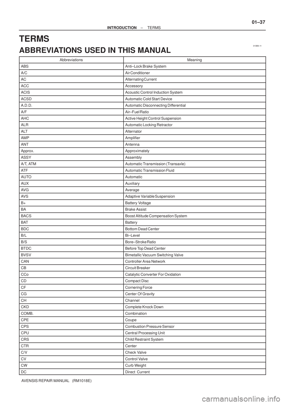
TERMS
ABBREVIATIONS USED IN THIS MANUAL
AbbreviationsMeaning
ABSAnti±Lock Brake System
A/CAir Conditioner
ACAlternating Current
ACCAccessory
ACISAcoustic Control Induction System
ACSDAutomatic Cold Start Device
A.D.D.Automatic Disconnecting Differential
A/FAir±Fuel Ratio
AHCActive Height Control Suspension
ALRAutomatic Locking Retractor
ALTAlternator
AMPAmplifier
ANTAntenna
Approx.Approximately
ASSYAssembly
A/T, ATMAutomatic Transmission (Transaxle)
AT FAutomatic Transmission Fluid
AUTOAutomatic
AUXAuxiliary
AV GAverage
AV SAdaptive Variable Suspension
B+Battery Voltage
BABrake Assist
BACSBoost Altitude Compensation System
BATBattery
BDCBottom Dead Center
B/LBi±Level
B/SBore±Stroke Ratio
BTDCBefore Top Dead Center
BVSVBimetallic Vacuum Switching Valve
CANController Area Network
CBCircuit Breaker
CCoCatalytic Converter For Oxidation
CDCompact Disc
CFCornering Force
CGCenter Of Gravity
CHChannel
CKDComplete Knock Down
COMB.Combination
CPECoupe
CPSCombustion Pressure Sensor
CPUCentral Processing Unit
CRSChild Restraint System
CTRCenter
C/VCheck Valve
CVControl Valve
CWCurb Weight
DCDirect Current
Page 873 of 5135
F45132
Battery FL MAINSkid Control ECU
with Actuator
B±G (*1) L (*1)
1 ALT VSC Engine Room R/B No.4 & Engine Room J/B No.4
1
4B
W±BS1
S1109
+BM
12
1 2
GND1 GND2
S16
W±BW±B
*1: 1AZ±FSE
*2: 1CD±FTVEA4
L (*2)
W (*2)
2 12 33 11B1 ALT Engine Room R/B No.3Engine Room R/B No.1 &
Engine Room J/B No.1
B (*2)
B±G (*1)VSC 05±784
± DIAGNOSTICSABS WITH EBD & BA & TRC & VSC SYSTEM
AVENSIS REPAIR MANUAL (RM1018E)
DTC C0273/13 OPEN OR SHORT CIRCUIT IN ABS MOTOR
RELAY CIRCUIT
CIRCUIT DESCRIPTION
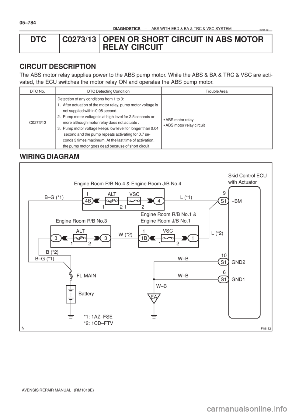
The ABS motor relay supplies power to the ABS pump motor. While the ABS & BA & TRC & VSC are acti-
vated, the ECU switches the motor relay ON and operates the ABS pump motor.
DTC No.DTC Detecting ConditionTrouble Area
C0273/13
Detection of any conditions from 1 to 3:
1. After actuation of the motor relay, pump motor voltage is
not supplied within 0.08 second.
2. Pump motor voltage is at high level for 2.5 seconds or
more although motor relay does not actuate .
3. Pump motor voltage keeps low level for longer than 0.04
second and the pump repeats activating for 0.7 se-
conds 3 times maximum. At the last time of activation,
the pump motor goes dead because of short circuit.
�ABS motor relay
�ABS motor relay circuit
WIRING DIAGRAM
05781±02
Page 1544 of 5135
I35660
±
DIAGNOSTICS NAVIGATION SYSTEM
05±1491
AVENSIS REPAIR MANUAL (RM1018E)
A NAVIGATION CONTROLLER ASSY DOES NOT OPERATE
INSPECTION PROCEDURE
1CHECK MALFUNCTION SYMPTOMS
(a)Check obstruction.
(1)Check that there are no obstructions between the navigation controller assy a\
nd the infrared ray
light emission portion of the multi±display (CRT display) display.
Standard: Normally returns
OKSYSTEM OK
NG
2CHECK BATTERY(NAVIGATION CONTROLLER ASSY)
(a)Check battery. (1)Check that the dry±cell battery used for the navigation controller as\
sy is not dead.
Standard: It is not dead
NGBATTERY IS DEAD
OK
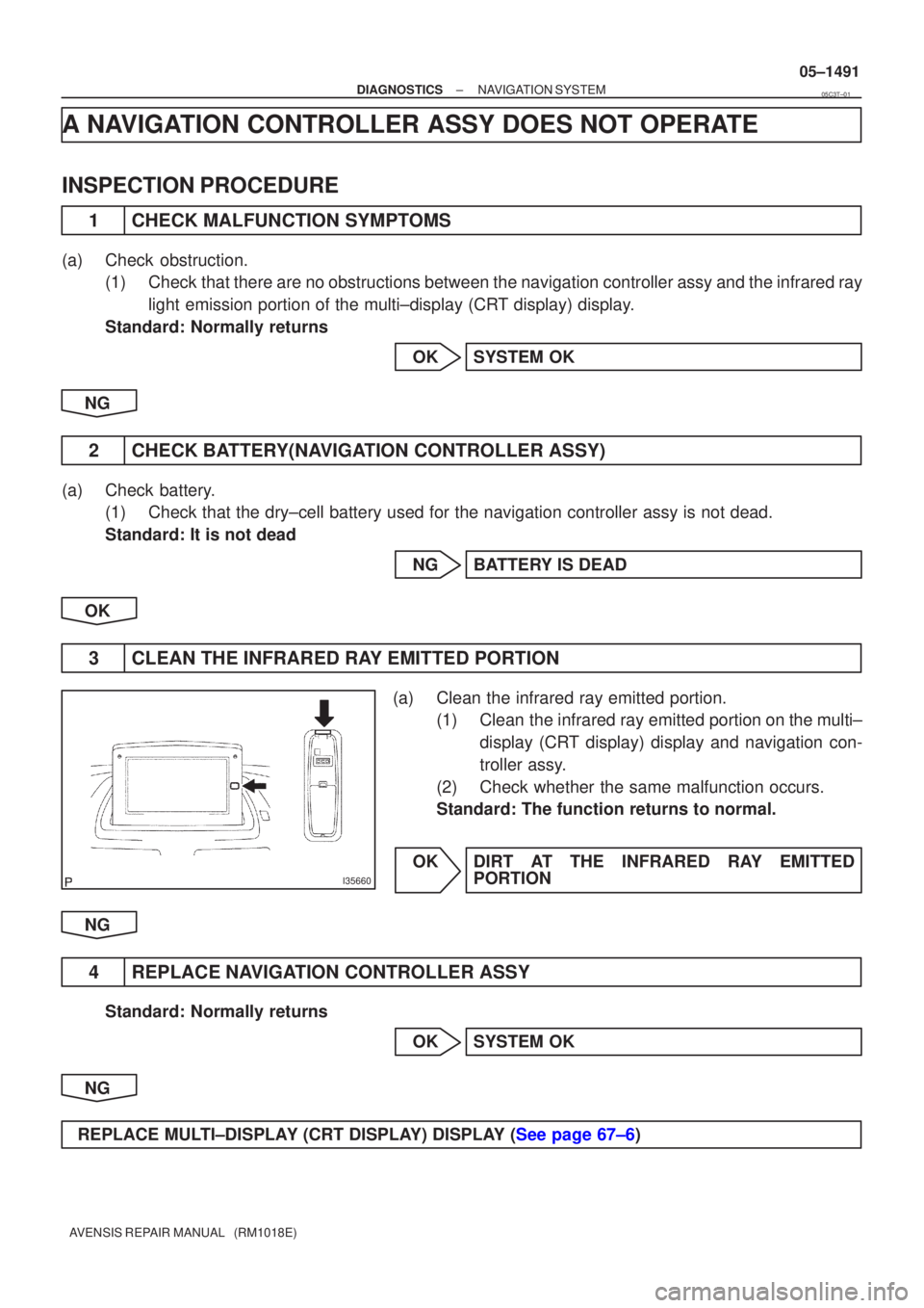
3CLEAN THE INFRARED RAY EMITTED PORTION
(a)Clean the infrared ray emitted portion. (1)Clean the infrared ray emitted portion on the multi±
display (CRT display) display and navigation con-
troller assy.
(2)Check whether the same malfunction occurs.
Standard: The function returns to normal.
OKDIRT AT THE INFRARED RAY EMITTED PORTION
NG
4REPLACE NAVIGATION CONTROLLER ASSY
Standard: Normally returns OKSYSTEM OK
NG
REPLACE MULTI±DISPLAY (CRT DISPLAY) DISPLAY (See page 67±6)
05C3T±01
Page 3333 of 5135
73±2
± THEFT DETERRENT & DOOR LOCKPOWER DOOR LOCK CONTROL SYSTEM
AVENSIS REPAIR MANUAL (RM1018E)
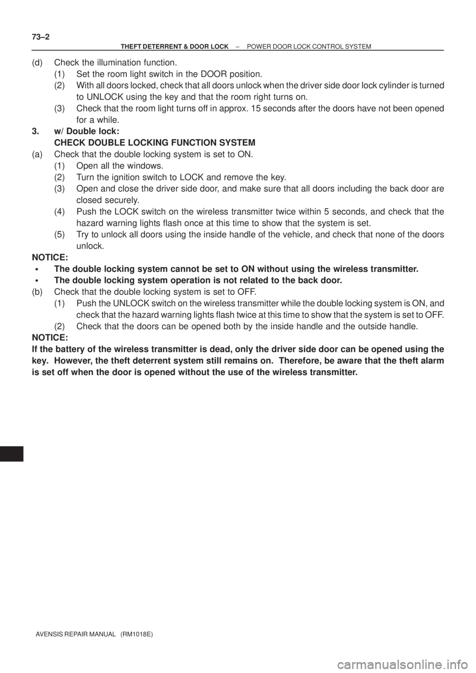
(d) Check the illumination function.
(1) Set the room light switch in the DOOR position.
(2) With all doors locked, check that all doors unlock when the driver side door lock cylinder is turned
to UNLOCK using the key and that the room right turns on.
(3) Check that the room light turns off in approx. 15 seconds after the doors have not been opened
for a while.
3. w/ Double lock:
CHECK DOUBLE LOCKING FUNCTION SYSTEM
(a) Check that the double locking system is set to ON.
(1) Open all the windows.
(2) Turn the ignition switch to LOCK and remove the key.
(3) Open and close the driver side door, and make sure that all doors including the back door are
closed securely.
(4) Push the LOCK switch on the wireless transmitter twice within 5 seconds, and check that the
hazard warning lights flash once at this time to show that the system is set.
(5) Try to unlock all doors using the inside handle of the vehicle, and check that none of the doors
unlock.
NOTICE:
�The double locking system cannot be set to ON without using the wireless transmitter.
�The double locking system operation is not related to the back door.
(b) Check that the double locking system is set to OFF.
(1) Push the UNLOCK switch on the wireless transmitter while the double locking system is ON, and
check that the hazard warning lights flash twice at this time to show that the system is set to OFF.
(2) Check that the doors can be opened both by the inside handle and the outside handle.
NOTICE:
If the battery of the wireless transmitter is dead, only the driver side door can be opened using the
key. However, the theft deterrent system still remains on. Therefore, be aware that the theft alarm
is set off when the door is opened without the use of the wireless transmitter.
Page 3462 of 5135
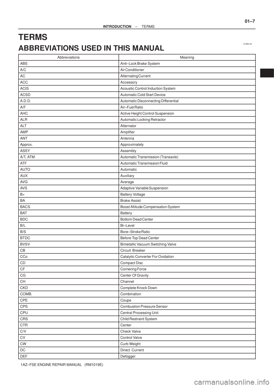
010B9±09
± INTRODUCTIONTERMS
01±7
1AZ±FSE ENGINE REPAIR MANUAL (RM1019E)
TERMS
ABBREVIATIONS USED IN THIS MANUAL
AbbreviationsMeaning
ABSAnti±Lock Brake System
A/CAir Conditioner
ACAlternating Current
ACCAccessory
ACISAcoustic Control Induction System
ACSDAutomatic Cold Start Device
A.D.D.Automatic Disconnecting Differential
A/FAir±Fuel Ratio
AHCActive Height Control Suspension
ALRAutomatic Locking Retractor
ALTAlternator
AMPAmplifier
ANTAntenna
Approx.Approximately
ASSYAssembly
A/T, ATMAutomatic Transmission (Transaxle)
AT FAutomatic Transmission Fluid
AUTOAutomatic
AUXAuxiliary
AV GAverage
AV SAdaptive Variable Suspension
B+Battery Voltage
BABrake Assist
BACSBoost Altitude Compensation System
BATBattery
BDCBottom Dead Center
B/LBi±Level
B/SBore±Stroke Ratio
BTDCBefore Top Dead Center
BVSVBimetallic Vacuum Switching Valve
CBCircuit Breaker
CCoCatalytic Converter For Oxidation
CDCompact Disc
CFCornering Force
CGCenter Of Gravity
CHChannel
CKDComplete Knock Down
COMB.Combination
CPECoupe
CPSCombustion Pressure Sensor
CPUCentral Processing Unit
CRSChild Restraint System
CTRCenter
C/VCheck Valve
CVControl Valve
CWCurb Weight
DCDirect Current
DEFDefogger