Page 2463 of 5135
2600K±06
±
FRONT SUSPENSION FRONT SUSPENSION SYSTEM
26±1
AVENSIS REPAIR MANUAL (RM1018E)
FRONT SUSPENSION SYSTEM
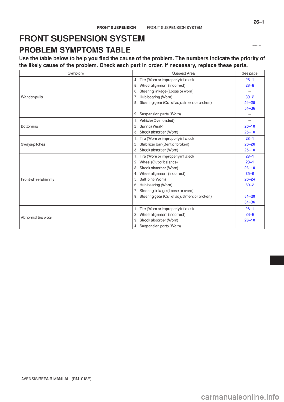
PROBLEM SYMPTOMS TABLE
Use the table below to help you find the cause of the problem. The numbers \
indicate the priority of
the likely cause of the problem. Check each part in order. If necessary, replace these parts.
SymptomSuspect AreaSee page
Wander/pulls
4. Tire (Worn or improperly inflated)
5. Wheel alignment (Incorrect)
6. Steering linkage (Loose or worn)
7. Hub bearing (Worn)
8. Steering gear (Out of adjustment or broken)
9. Suspension parts (Worn)28±1
26±6
±
30±2
51±28
51±36
±
Bottoming
1. Vehicle (Overloaded)
2. Spring (Weak)
3. Shock absorber (Worn)±
26±10
26±10
Sways/pitches
1. Tire (Worn or improperly inflated)
2. Stabilizer bar (Bent or broken)
3. Shock absorber (Worn)28±1
26±26
26±10
Front wheel shimmy
1. Tire (Worn or improperly inflated)
2. Wheel (Out of balance)
3. Shock absorber (Worn)
4. Wheel alignment (Incorrect)
5. Ball joint (Worn)
6. Hub bearing (Worn)
7. Steering linkage (Loose or worn)
8. Steering gear (Out of adjustment or broken)28±1
28±1
26±10 26±6
26±24
30±2 ±
51±28
51±36
Abnormal tire wear
1. Tire (Worn or improperly inflated)
2. Wheel alignment (Incorrect)
3. Shock absorber (Worn)
4. Suspension parts (Worn)28±1
26±6
26±10 ±
Page 2496 of 5135
G23865
±
REAR SUSPENSION REAR SHOCK ABSORBER WITH COIL SPRING
27±13
AVENSIS REPAIR MANUAL (RM1018E)
24. FULLY TIGHTEN REAR SHOCK ABSORBER WITH
COIL SPRING
(a) Fully tighten the bolt and nut.
Torque: 160 N �m (1,632 kgf �cm, 118 ft �lbf)
NOTICE:
�When installing the bolt, hold the nut not to rotate.
�Be sure to empty the vehicle when fully tightening the
bolt and nut.
25.INSPECT AND ADJUST REAR WHEEL ALIGNMENT (See page 27±4)
26. CHECK ABS SPEED SENSOR SIGNAL
(a)ABD WITH EBD SYSTEM (See page 05±699)
(b)ABD WITH EBD & BA & TRC & VSC SYSTEM ( See page 05±756)
Page 2497 of 5135
270E1±01
SA3213
AD B
Front
C
G23862
27±4
±
REAR SUSPENSION REAR WHEEL ALIGNMENT
AVENSIS REPAIR MANUAL (RM1018E)
REAR WHEEL ALIGNMENT
ADJUSTMENT
1.INSPECT TIRE (See page 28±1)
2.MEASURE VEHICLE HEIGHT (See page 26±6)
NOTICE:
Before inspecting the wheel alignment, adjust the vehicle height to the \
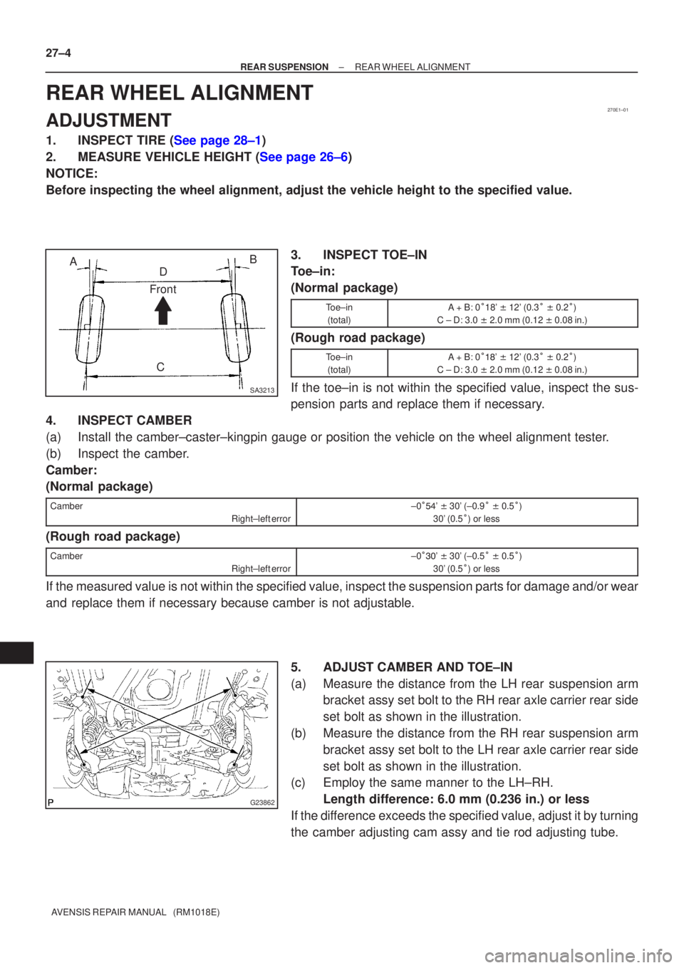
specified value. 3. INSPECT TOE±IN
Toe±in:
(Normal package)
Toe±in(total)A + B: 0 �18' \b 12' (0.3 � \b 0.2 �)
C ± D: 3.0 \b 2.0 mm (0.12 \b 0.08 in.)
(Rough road package)
Toe±in
(total)A + B: 0 ���' \b 12' (0.3 � \b 0.2 �)
C ± D: 3.0 \b 2.0 mm (0.12 \b 0.08 in.)
If the toe±in is not within the specified value, inspect the sus-
pension parts and replace them if necessary.
4. INSPECT CAMBER
(a) Install the camber±caster±kingpin gauge or position the vehicle on\
the wheel alignment tester.
(b) Inspect the camber.
Camber:
(Normal package)
Camber
Right±left error±0��� ' \b 30' (±0.9 � \b 0.5 �)
30' (0.5 �) or less
(Rough road package)
Camber
Right±left error±0��� ' \b 30' (±0.5 � \b 0.5 �)
30' (0.5 �) or less
If the measured value is not within the specified value, inspect the suspension parts for damage and/or wear
and replace them if necessary because camber is not adjustable.
5. ADJUST CAMBER AND TOE±IN
(a) Measure the distance from the LH rear suspension armbracket assy set bolt to the RH rear axle carrier rear side
set bolt as shown in the illustration.
(b) Measure the distance from the RH rear suspension arm bracket assy set bolt to the LH rear axle carrier rear side
set bolt as shown in the illustration.
(c) Employ the same manner to the LH±RH.
Length difference: 6.0 mm (0.236 in.) or less
If the difference exceeds the specified value, adjust it by turning
the camber adjusting cam assy and tie rod adjusting tube.
Page 2498 of 5135
G23877
G23886
Outward Inward
LongerShorterInward Outward
Front
Longer Shorter CAMBER ADJUSTING CAM ASSY
TIE ROD ADJUSTING TUBE
± REAR SUSPENSIONREAR WHEEL ALIGNMENT
27±5
AVENSIS REPAIR MANUAL (RM1018E)
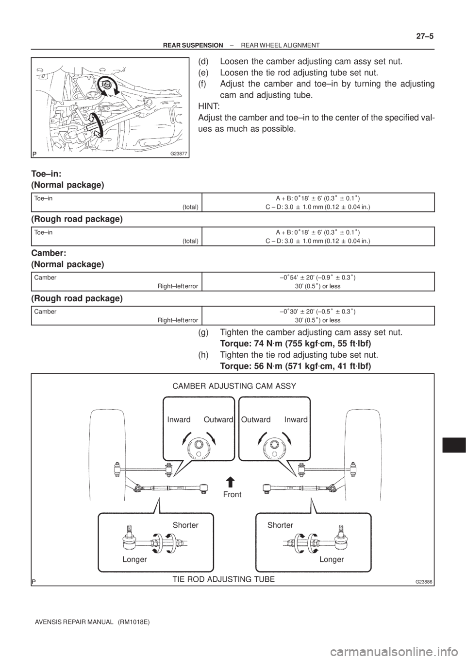
(d) Loosen the camber adjusting cam assy set nut.
(e) Loosen the tie rod adjusting tube set nut.
(f) Adjust the camber and toe±in by turning the adjusting
cam and adjusting tube.
HINT:
Adjust the camber and toe±in to the center of the specified val-
ues as much as possible.
Toe±in:
(Normal package)
Toe±in
(total)A + B: 0���' � 6' (0.3� � 0.1�)
C ± D: 3.0 � 1.0 mm (0.12 � 0.04 in.)
(Rough road package)
Toe±in
(total)A + B: 0���' � 6' (0.3� � 0.1�)
C ± D: 3.0 � 1.0 mm (0.12 � 0.04 in.)
Camber:
(Normal package)
Camber
Right±left error±0���' � 20' (±0.9� � 0.3�)
30' (0.5�) or less
(Rough road package)
Camber
Right±left error±0���' � 20' (±0.5� � 0.3�)
30' (0.5�) or less
(g) Tighten the camber adjusting cam assy set nut.
Torque: 74 N�m (755 kgf�cm, 55 ft�lbf)
(h) Tighten the tie rod adjusting tube set nut.
Torque: 56 N�m (571 kgf�cm, 41 ft�lbf)
Page 2499 of 5135
G23890
Example:
Camber
To e
1�00'
(1.0�)
(Scale) 0 2 4 6
27±6
± REAR SUSPENSIONREAR WHEEL ALIGNMENT
AVENSIS REPAIR MANUAL (RM1018E)
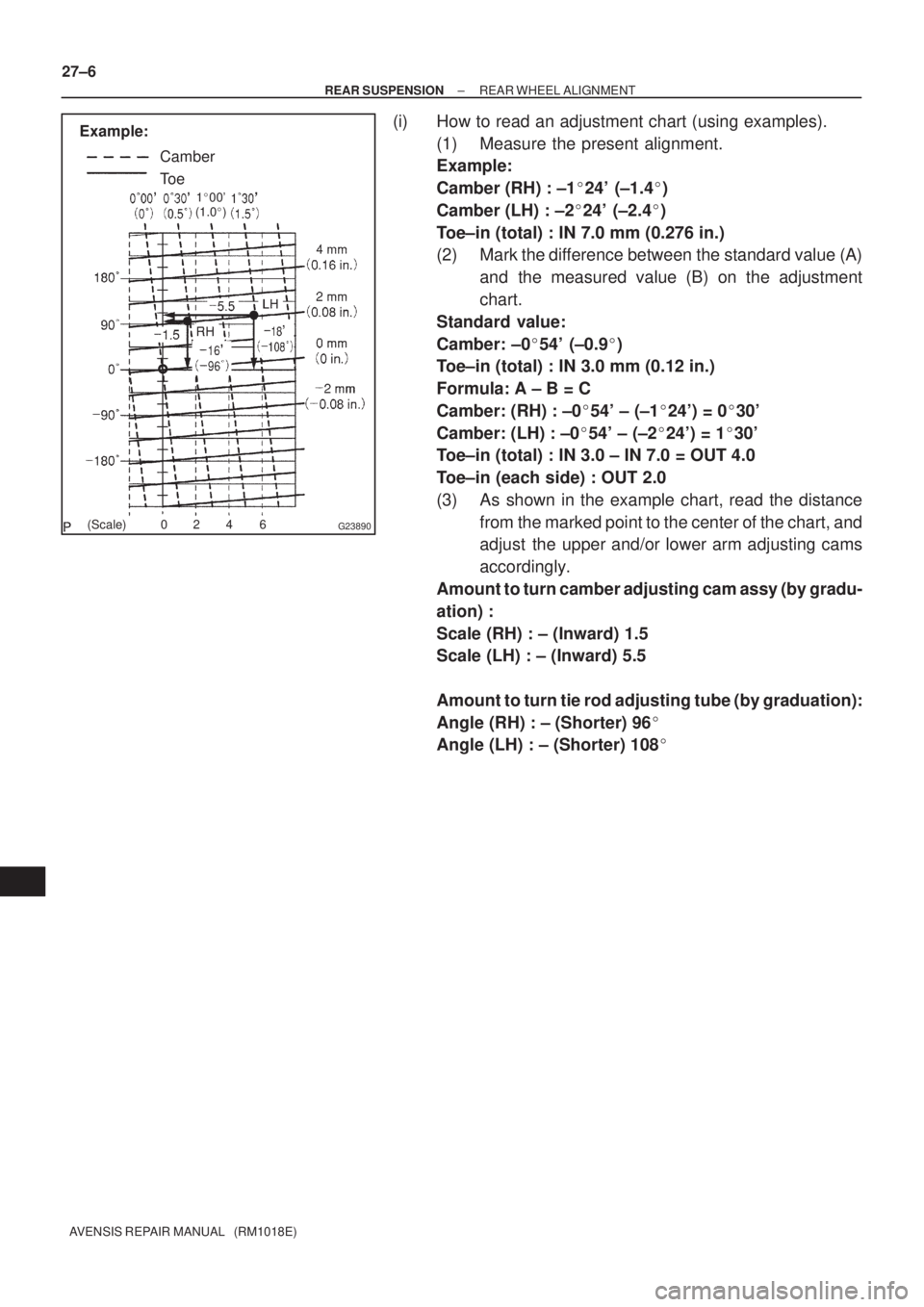
(i) How to read an adjustment chart (using examples).
(1) Measure the present alignment.
Example:
Camber (RH) : ±1�24' (±1.4�)
Camber (LH) : ±2�24' (±2.4�)
Toe±in (total) : IN 7.0 mm (0.276 in.)
(2) Mark the difference between the standard value (A)
and the measured value (B) on the adjustment
chart.
Standard value:
Camber: ±0�54' (±0.9�)
Toe±in (total) : IN 3.0 mm (0.12 in.)
Formula: A ± B = C
Camber: (RH) : ±0�54' ± (±1�24') = 0�30'
Camber: (LH) : ±0�54' ± (±2�24') = 1�30'
Toe±in (total) : IN 3.0 ± IN 7.0 = OUT 4.0
Toe±in (each side) : OUT 2.0
(3) As shown in the example chart, read the distance
from the marked point to the center of the chart, and
adjust the upper and/or lower arm adjusting cams
accordingly.
Amount to turn camber adjusting cam assy (by gradu-
ation) :
Scale (RH) : ± (Inward) 1.5
Scale (LH) : ± (Inward) 5.5
Amount to turn tie rod adjusting tube (by graduation):
Angle (RH) : ± (Shorter) 96�
Angle (LH) : ± (Shorter) 108�
Page 2500 of 5135
G23889
Camber
To e
Longer
Tie Rod
Adjusting Tube
Shorter
InwardCamber Adjusting
Cam AssyOutward
± REAR SUSPENSIONREAR WHEEL ALIGNMENT
27±7
AVENSIS REPAIR MANUAL (RM1018E)
Page 2503 of 5135
270E7±01
±
REAR SUSPENSION REAR SUSPENSION SYSTEM
27±1
AVENSIS REPAIR MANUAL (RM1018E)
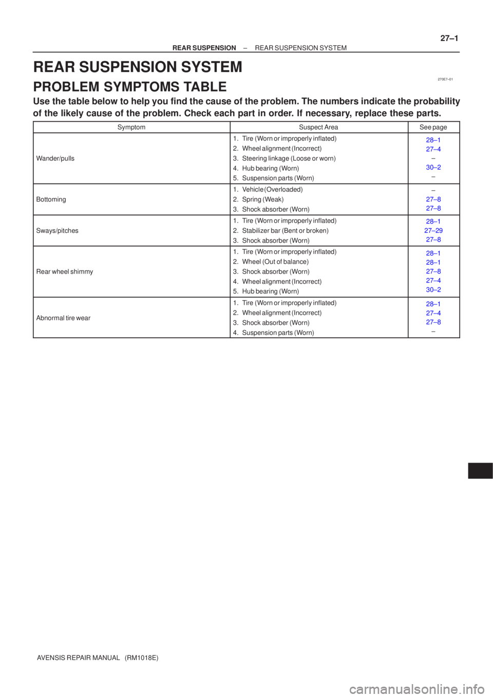
REAR SUSPENSION SYSTEM
PROBLEM SYMPTOMS TABLE
Use the table below to help you find the cause of the problem. The numbers \
indicate the probability
of the likely cause of the problem. Check each part in order. If necessary, replace these parts.
SymptomSuspect AreaSee page
Wander/pulls
1. Tire (Worn or improperly inflated)
2. Wheel alignment (Incorrect)
3. Steering linkage (Loose or worn)
4. Hub bearing (Worn)
5. Suspension parts (Worn)28±1
27±4
±
30±2 ±
Bottoming
1. Vehicle (Overloaded)
2. Spring (Weak)
3. Shock absorber (Worn)±
27±8
27±8
Sways/pitches
1. Tire (Worn or improperly inflated)
2. Stabilizer bar (Bent or broken)
3. Shock absorber (Worn)28±1
27±29 27±8
Rear wheel shimmy
1. Tire (Worn or improperly inflated)
2. Wheel (Out of balance)
3. Shock absorber (Worn)
4. Wheel alignment (Incorrect)
5. Hub bearing (Worn)28±1
28±1
27±8
27±4
30±2
Abnormal tire wear
1. Tire (Worn or improperly inflated)
2. Wheel alignment (Incorrect)
3. Shock absorber (Worn)
4. Suspension parts (Worn)28±1
27±4
27±8
±
Page 2506 of 5135
F45155
A
B
F44620
26±28
±
FRONT SUSPENSION STABILIZER BAR FRONT
AVENSIS REPAIR MANUAL (RM1018E)
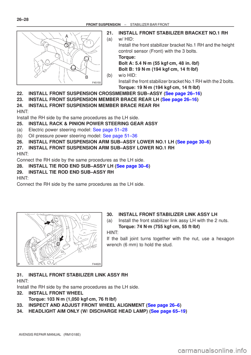
21. INSTALL FRONT STABILIZER BRACKET NO.1 RH
(a) w/ HID: Install the front stabilizer bracket No.1 RH and the height
control sensor (Front) with the 3 bolts.
Torque:
Bolt A: 5.4 N �m (55 kgf �cm, 48 in. �lbf)
Bolt B: 19 N �m (194 kgf �cm, 14 ft �lbf)
(b) w/o HID: Install the front stabilizer bracket No.1 RH with the 2 bolts.
Torque: 19 N �m (194 kgf �cm, 14 ft �lbf)
22.INSTALL FRONT SUSPENSION CROSSMEMBER SUB±ASSY (See page 26±16)
23.INSTALL FRONT SUSPENSION MEMBER BRACE REAR LH (See page 26±16)
24. INSTALL FRONT SUSPENSION MEMBER BRACE REAR RH
HINT:
Install the RH side by the same procedures as the LH side.
25. INSTALL RACK & PINION POWER STEERING GEAR ASSY
(a)Electric power steering model: See page 51±28
(b)Oil pressure power steering model: See page 51±36
26.INSTALL FRONT SUSPENSION ARM SUB±ASSY LOWER NO.1 LH (See page 30±6)
27. INSTALL FRONT SUSPENSION ARM SUB±ASSY LOWER NO.1 RH
HINT:
Connect the RH side by the same procedures as the LH side.
28.INSTALL TIE ROD END SUB±ASSY LH (See page 30±6)
29. INSTALL TIE ROD END SUB±ASSY RH
HINT:
Connect the RH side by the same procedures as the LH side.
30. INSTALL FRONT STABILIZER LINK ASSY LH
(a) Install the front stabilizer link assy LH with the 2 nuts.Torque: 74 N �m (755 kgf �cm, 55 ft �lbf)
HINT:
If the ball joint turns together with the nut, use a hexagon
wrench (6 mm) to hold the stud.
31. INSTALL FRONT STABILIZER LINK ASSY RH
HINT:
Install the RH side by the same procedures as the LH side.
32. INSTALL FRONT WHEEL Torque: 103 N �m (1,050 kgf �cm, 76 ft �lbf)
33.INSPECT AND ADJUST FRONT WHEEL ALIGNMENT (See page 26±6)
34.HEADLIGHT AIM ONLY (W/ DISCHARGE HEAD LAMP) (See page 65±19)