Page 1919 of 5135
A79436
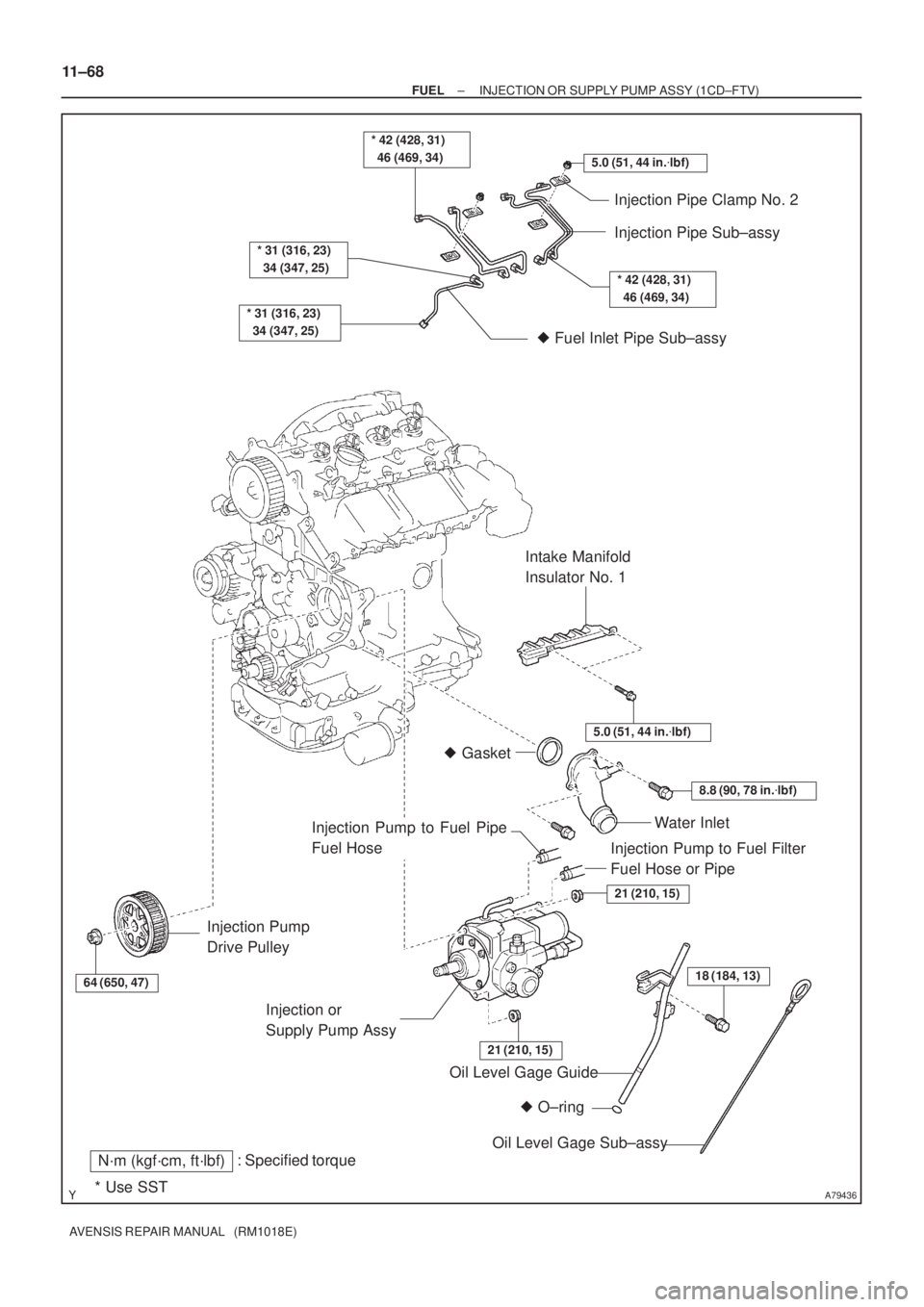
5.0 (51, 44 in.�lbf)
* 42 (428, 31)
46 (469, 34)
* 31 (316, 23)
34 (347, 25)
* 31 (316, 23)
34 (347, 25)
Injection Pipe Clamp No. 2
Injection Pipe Sub±assy
� Fuel Inlet Pipe Sub±assy
64 (650, 47)
Injection Pump
Drive Pulley
� O±ring Oil Level Gage Guide
: Specified torqueN´m (kgf´cm, ft´lbf)
* Use SST
18 (184, 13)
Oil Level Gage Sub±assy Injection or
Supply Pump Assy
21 (210, 15)
21 (210, 15)
Water Inlet
8.8 (90, 78 in.�lbf)
� Gasket
5.0 (51, 44 in.�lbf)
Intake Manifold
Insulator No. 1
* 42 (428, 31)
46 (469, 34)
Injection Pump to Fuel Filter
Fuel Hose or Pipe
Injection Pump to Fuel Pipe
Fuel Hose
11±68
± FUELINJECTION OR SUPPLY PUMP ASSY (1CD±FTV)
AVENSIS REPAIR MANUAL (RM1018E)
Page 1986 of 5135

14±1
AVENSIS REPAIR MANUAL (RM1018E)
ENGINE(1ZZ±FE/3ZZ±FE)
INSPECTION
1.INSPECT COOLANT (See page 16±1)
2.INSPECT ENGINE")
140KR±02
A62199
TCCG
A62200
±
ENGINE MECHANICAL ENGINE(1ZZ±FE/3ZZ±FE)
14±1
AVENSIS REPAIR MANUAL (RM1018E)
ENGINE(1ZZ±FE/3ZZ±FE)
INSPECTION
1.INSPECT COOLANT (See page 16±1)
2.INSPECT ENGINE OIL (See page 17±1)
3.INSPECT BATTERY (See page 19±5)
4.INSPECT AIR CLEANER FILTER ELEMENT SUB±ASSY
5.INSPECT SPARK PLUG (See page 18±3)
6.INSPECT FAN AND GENERATOR V BELT
HINT:
You don't need to check the belt deflection because auto tensioner is ado\
pted.
7.INSPECT IGNITION TIMING
(a)Warm up engine.
(b)When using hand±held tester:
(1)Connect the hand±held tester to the DLC3.
(2)Enter DATA LIST MODE on the hand±held tester.
Ignition timing: 8 to 12 �BTDC
HINT:
Please refer to the hand±held tester operator's manual if you
need help to select DATA LIST.
(c) When not using hand±held tester: (1) Using SST, connect terminal 13 (TC) and 4 (CG) ofthe DLC3.
SST 09843±18040
NOTICE:
�Make sure of the terminal numbers before connecting
them. Connection with a wrong terminal can damage
the engine.
�Turn OFF all electrical systems before connecting the
terminals.
�Operate the inspection after the cooling fan motor is
turned OFF
(2) Remove the 2 nuts, and 2 clips, and then remove the cylinder head cover.
(3) Pull out the wire harness as shown in the illustration.
(4) Connect the clip of the timing light to the engine.
NOTICE:
�Use a timing light which detects the first signal.
�After checking, be sure to wrap the wire harness with
tape.
Page 2044 of 5135

AVENSIS REPAIR MANUAL (RM1018E)
7.REMOVE ENGINE UNDER COVER RH
(a)Remove the 6 screws and 3 clips, then detach the engi")
A78516
A78459
14±28
±
ENGINE MECHANICAL PARTIAL ENGINE ASSY(1ZZ±FE/3ZZ±FE)
AVENSIS REPAIR MANUAL (RM1018E)
7.REMOVE ENGINE UNDER COVER RH
(a)Remove the 6 screws and 3 clips, then detach the engine under cover.
8.DRAIN ENGINE COOLANT(See page 16±7)
9. DRAIN ENGINE OIL
(a) Install a new gasket and the drain plug after draining engine oil. Torque: 37 N �m (377 kgf �cm, 27 ft �lbf)
10.DRAIN MANUAL TRANSAXLE OIL (M/T TRANSAXLE) (See page 41±15)
11.DRAIN AUTOMATIC TRANSAXLE FLUID (A/T TRANSAXLE) (See page 40±42)
12. REMOVE CYLINDER HEAD COVER NO.2
(a) Remove the 2 nuts and 2 clips, then detach cylinder headcover No.2.
13.REMOVE AIR CLEANER ASSEMBLY WITH HOSE (See page 10±9 or 10±15)
14. REMOVE AIR CLEANER FILTER ELEMENT SUB±ASSY
15. REMOVE AIR CLEANER CASE SUB±ASSY
(a) Remove the 3 bolts and the air cleaner case.
16. DISCONNECT RADIATOR HOSE INLET
(a) Disconnect the radiator hose inlet from the radiator.
17. DISCONNECT RADIATOR HOSE OUTLET
(a) Disconnect the radiator hose outlet from the radiator.
18. DISCONNECT OIL COOLER INLET TUBE NO.1 (A/T TRANSAXLE)
(a) Disconnect the oil cooler inlet tube from the radiator.
19. DISCONNECT OIL COOLER OUTLET TUBE NO.1 (A/T TRANSAXLE)
(a) Disconnect the oil cooler outlet tube from the radiator.
Page 2062 of 5135
A76702
Accelerator Control Cable Assy
Heater Inlet Water Hose
Fuel Pipe Clamp
Fuel Tube Sub±assy
Heater Outlet Water Hose
Air Cleaner Cap
W/ Hose
Air Cleaner Filter
Element Sub±assy
Air Cleaner Case Sub±assy Battery Clamp
Sub±assy
Battery
Battery Tray
Battery Carrier
12.8 (131, 9)
N´m (kgf´cm, ft´lbf)
: Specified torque
Union to Connector Tube Hose
Air Cleaner Clamp
Bracket
5.0 (51, 44 in.�lbf)
Fuel Vapor Feed Hose No.1
Fuel Vapor Feed Hose No.3
5.0 (51, 44 in.�lbf)
Oil Cooler
Inlet Hose
Oil Cooler
Outlet Hose
X4
VSV Connector
Mass Air Flow
Meter Connector
14±20
± ENGINE MECHANICALPARTIAL ENGINE ASSY (1ZZ±FE/3ZZ±FE)
AVENSIS REPAIR MANUAL (RM1018E)
Page 2099 of 5135

14±101
AVENSIS REPAIR MANUAL (RM1018E)
ENGINE(1AZ±FE)
INSPECTION
1.INSPECT COOLANT (See page 16±13)
2.INSPECT ENGINE OIL (See pag")
140D1±02
CG
TCA51075
A52004
±
ENGINE MECHANICAL ENGINE(1AZ±FE)
14±101
AVENSIS REPAIR MANUAL (RM1018E)
ENGINE(1AZ±FE)
INSPECTION
1.INSPECT COOLANT (See page 16±13)
2.INSPECT ENGINE OIL (See page 17±6)
3. INSPECT BATTERY
Standard specific gravity: 1.25 to 1.29 at 20 �C (68 �F)
4. INSPECT AIR CLEANER FILTER ELEMENT SUB±ASSY
5.INSPECT SPARK PLUG (See page 18±9)
6. INSPECT V±RIBBED BELT
7. INSPECT IGNITION TIMING
(a) Warm up engine.
(b) When using hand±held tester:(1) Connect the hand±held tester to the DLC3.
(2) Enter DATA LIST MODE on the hand±held tester.
Ignition timing: 8 to 12 � BTDC
HINT:
Please refer to the hand±held tester operator's manual if you
need help to select DATA LIST.
(c) When not using hand±held tester:
(1) Using SST, connect terminals 13 (TC) and 4 (CG)of DLC3.
SST 09843±18040
NOTICE:
�Make sure of the terminal numbers before connecting
them. Connection with a wrong terminal can damage
the engine.
�Turn OFF all electrical systems before connecting the
terminals.
�Operate the inspection after the cooling fan motor is
turned OFF.
(2) Remove the cylinder head cover No.2.
(3) Pull out the wire harness as shown in the illustration.
Connect the clip of the timing light to the engine.
NOTICE:
�Use a timing light which detects the first signal.
�After checking, be sure to wrap the wire harness with
tape.
(4) Inspect ignition timing at idle.
Ignition timing: 8 to 12 � BTDC
NOTICE:
When checking the ignition timing, shift the transmission
to the neutral position.
HINT:
Run the engine at 1,000 to 1,300 rpm for 5 seconds, check that
the engine rpm returns to the idle speed.
Page 2128 of 5135

14±181
AVENSIS REPAIR MANUAL (RM1018E)
ENGINE(1AZ±FSE)
INSPECTION
1.INSPECT COOLANT (See page 16±25)
2.INSPECT ENGINE OIL(See pa")
141CP±01
CG
TCA51075
A79034
±
ENGINE MECHANICAL ENGINE(1AZ±FSE)
14±181
AVENSIS REPAIR MANUAL (RM1018E)
ENGINE(1AZ±FSE)
INSPECTION
1.INSPECT COOLANT (See page 16±25)
2.INSPECT ENGINE OIL(See page 17±13)
3.INSPECT BATTERY
Standard specific gravity: 1.25 to 1.29 at 20 �C (68 �F)
4.INSPECT AIR CLEANER FILTER ELEMENT SUB±ASSY
5.INSPECT SPARK PLUG (See page 18±14)
6.INSPECT V±RIBBED BELT
7.INSPECT IGNITION TIMING
(a)Warm up engine.
(b)When using hand±held tester:(1)Connect the hand±held tester to the DLC3.
(2)Enter DATA LIST MODE on the hand±held tester.
Ignition timing: 8 to 12 � BTDC
HINT:
Please refer to the hand±held tester operator's manual if you
need help to select DATA LIST.
(c) When not using hand±held tester:
(1) Using SST, connect terminals 13 (TC) and 4 (CG)of DLC3.
SST 09843±18040, 09843±18020
NOTICE:
�Make sure of the terminal numbers before connecting
them. Connection with a wrong terminal can damage
the engine.
�Turn OFF all electrical systems before connecting the
terminals.
�Operate the inspection after the cooling fan motor is
turned OFF
(2) Remove the cylinder head cover No.2.
(3) Pull out the wire harness as shown in the illustration.
Connect the clip of the timing light to the engine.
NOTICE:
�Use a timing light which detects the first signal.
�After checking, be sure to wrap the wire harness with
tape.
(4) Inspect ignition timing at idle.
Ignition timing: 8 to 12 � BTDC
NOTICE:
When checking the ignition timing, shift the transmission
to the neutral position.
HINT:
Run the engine at 1,000 to 1,300 rpm for 5 seconds, check that
the engine rpm returns to the idle speed. (5) Disconnect terminals 13 (TC) and 4 (CG) of DLC3.
Page 2241 of 5135
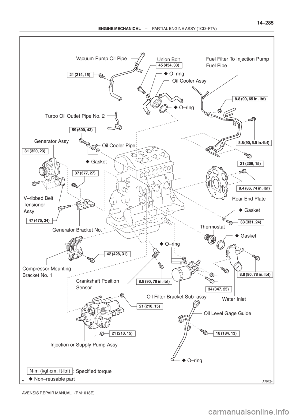
A79424
N´m (kgf´cm, ft´lbf)
: Specified torque
� Non±reusable part
8.8 (90, 65 in.�lbf)
8.8 (90, 6.5 in.�lbf)
8.4 (86, 74 in.�lbf)
21 (209, 15)
8.8 (90, 78 in.�lbf)
34 (347, 25)
18 (184, 13)21 (210, 15)
21 (210, 15)
42 (428, 31)
37 (377, 27)
59 (600, 43)
21 (214, 15)
45 (454, 33)
� O±ring
� O±ring
� Gasket
� O±ring
� O±ring
Vacuum Pump Oil Pipe
Union Bolt
Oil Cooler AssyFuel Filter To Injection Pump
Fuel Pipe
Rear End Plate
Crankshaft Position
Sensor
Thermostat
Water Inlet
Oil Level Gage Guide Oil Filter Bracket Sub±assy
Injection or Supply Pump Assy Compressor Mounting
Bracket No. 1Generator Bracket No. 1 V±ribbed Belt
Tensioner
AssyGenerator Assy
Oil Cooler Pipe
� Gasket
Turbo Oil Outlet Pipe No. 2
31 (320, 23)
� Gasket
33 (331, 24)
8.8 (90, 78 in.�lbf)
47 (475, 34)
± ENGINE MECHANICALPARTIAL ENGINE ASSY (1CD±FTV)
14±285
AVENSIS REPAIR MANUAL (RM1018E)
Page 2250 of 5135

140DD±03
A57063
Measure Point for Belt
Deflection and Tension
Alternator
Crankshaft Compressor
P/S P/S
Alternator Crankshaft
A/C equipped
A/C not equipped
A61173
B
A
14±266
±
ENGINE MECHANICAL ENGINE(1CD±FTV)
AVENSIS REPAIR MANUAL (RM1018E)
ENGINE(1CD±FTV)
INSPECTION
1.INSPECT COOLANT (See page 16±37)
2.INSPECT ENGINE OIL (See page 17±20)
3.INSPECT BATTERY (See page 19±26)
4. INSPECT AIR CLEANER FILTER ELEMENT SUB±ASSY 5. INSPECT DRIVE BELT
(a) Inspect vane pump V belt.(1) Measure the belt deflection
Pressing force: 98 N �m (10 kgf 22 lbf)
New belt
mm (in.)Used belt mm (in.)
A/C equipped9.5 to 11.5
(0.37 to 0.45)12.5 to 15.5
(0.49 to 0.61)
A/C not equipped10 to 12
(0.39 to 0.47)14 to 17
(0.55 to 0.67)
(2) Measure the belt tension
New belt
N (kgf, lbf)Used belt
N (kgf, lbf)
A/C equipped519 to 755
(53 to 77, 117 to 170)196 to 392
(20 to 40, 44 to 88)
A/C not equipped686 to 784
(70 to 80, 154 to 176)294 to 441
(30 to 45, 66 to 99)
NOTICE:
�Check the drive belt deflection at the specified point.
�When installing a new belt, set its tension value as
specified.
�When inspecting the belt which is used over 5 min-
utes, apply the specifications of ºUsed Belt.º
�When reinstalling the belt which is used over 5 min-
utes, adjust its deflection and tension to the medium
value in each specification of ºUsed Belt.º
�V±ribbed belt tension and deflection should be
checked after 2 revolutions of engine cranking.
�When using a belt tension gauge, confirm the accura-
cy by using a master gauge first.
(b) Inspect generator V belt. (1) Check that the tension indicator is within range A onthe auto tensioner scale.
If the tension is not within the A range, replace the belt with a
new one.
HINT:
When replacing the drive belt with a new one, the belt tension
should be within the B range.