Page 11 of 5135

TERMS
ABBREVIATIONS USED IN THIS MANUAL
AbbreviationsMeaning
ABSAnti±Lock Brake System
A/CAir Conditioner
ACAlternating Current")
010B9±11
± INTRODUCTIONTERMS
01±37
AVENSIS REPAIR MANUAL (RM1018E)
TERMS
ABBREVIATIONS USED IN THIS MANUAL
AbbreviationsMeaning
ABSAnti±Lock Brake System
A/CAir Conditioner
ACAlternating Current
ACCAccessory
ACISAcoustic Control Induction System
ACSDAutomatic Cold Start Device
A.D.D.Automatic Disconnecting Differential
A/FAir±Fuel Ratio
AHCActive Height Control Suspension
ALRAutomatic Locking Retractor
ALTAlternator
AMPAmplifier
ANTAntenna
Approx.Approximately
ASSYAssembly
A/T, ATMAutomatic Transmission (Transaxle)
AT FAutomatic Transmission Fluid
AUTOAutomatic
AUXAuxiliary
AV GAverage
AV SAdaptive Variable Suspension
B+Battery Voltage
BABrake Assist
BACSBoost Altitude Compensation System
BATBattery
BDCBottom Dead Center
B/LBi±Level
B/SBore±Stroke Ratio
BTDCBefore Top Dead Center
BVSVBimetallic Vacuum Switching Valve
CANController Area Network
CBCircuit Breaker
CCoCatalytic Converter For Oxidation
CDCompact Disc
CFCornering Force
CGCenter Of Gravity
CHChannel
CKDComplete Knock Down
COMB.Combination
CPECoupe
CPSCombustion Pressure Sensor
CPUCentral Processing Unit
CRSChild Restraint System
CTRCenter
C/VCheck Valve
CVControl Valve
CWCurb Weight
DCDirect Current
Page 13 of 5135
Abbreviations Meaning
H±FUSEHigh Current Fuse
HIHigh
HIDHigh Intensity Discharge (Head Lamp)
HSGHousing
HTHard Top
HWSHeated Windshield Sy")
± INTRODUCTIONTERMS
01±39
AVENSIS REPAIR MANUAL (RM1018E)Abbreviations Meaning
H±FUSEHigh Current Fuse
HIHigh
HIDHigh Intensity Discharge (Head Lamp)
HSGHousing
HTHard Top
HWSHeated Windshield System
ICIntegrated Circuit
IDIIndirect Diesel Injection
IFSIndependent Front Suspension
IGIgnition
IIAIntegrated Ignition Assembly
INIntake (Manifold, Valve)
INTIntermittent
I/PInstrument Panel
IRSIndependent Rear Suspension
ISCIdle Speed Control
J/BJunction Block
J/CJunction Connector
KDKick±Down
LANLocal Area Network
LBLiftback
LCDLiquid Crystal Display
LEDLight Emitting Diode
LHLeft±Hand
LHDLeft±Hand Drive
L/H/WLength, Height, Width
LLCLong±Life Coolant
LNGLiquified Natural Gas
LOLow
LPGLiquified Petroleum Gas
LSDLimited Slip Differential
LSP & PVLoad Sensing Proportioning And Bypass Valve
LSPVLoad Sensing Proportioning Valve
MAPManifold Absolute Pressure
MAX.Maximum
MICMicrophone
MILMalfunction Indicator Lamp
MIN.Minimum
MG1Motor Generator No.1
MG2Motor Generator No.2
MPMultipurpose
MPIMultipoint Electronic Injection
MPXMultiplex Communication System
M/T, MTMManual Transmission (Transaxle)
MTMount
MTGMounting
NNeutral
NANatural Aspiration
No.Number
O2SOxygen Sensor
O/DOverdrive
Page 33 of 5135
Rubber Attachment
AttachmentBAL
Attachment Dimensions
85 mm (3.35 in.)
200 mm (7.87 in.) 100")
D30400
Swing Arm Type Lift
Plate Type LiftCenter of Lift
: CENTER OF VEHICLE
GRAVITY (unloaded condition)Rubber Attachment
AttachmentBAL
Attachment Dimensions
85 mm (3.35 in.)
200 mm (7.87 in.) 100 mm (3.94 in.)70 mm
(2.76 in.)
C
01±20
± INTRODUCTIONREPAIR INSTRUCTION
AVENSIS REPAIR MANUAL (RM1018E)
4. NOTICE FOR USING SWING ARM TYPE LIFT
(a) Follow the instruction manual of the lift for a safe operation.
(b) Use a cradle with a rubber attachment, as shown in the illustration.
(c) Set in the vehicle so as to make its center of gravity as close as possible to the center of the lift. (ºLº
becomes short.)
(d) Place the vehicle horizontally by adjusting the height of the cradle, and match the groove of the cradle
and the safety stand support location accurately.
(e) Be sure to lock the swing arm during the operation.
(f) Lift the vehicle up until the tires float, and shake the vehicle to make sure that the vehicle is stable.
5. NOTICE FOR USING PLATE TYPE LIFT
(a) Follow the instruction manual of the lift for a safe operation.
(b) Use a plate lift attachment.
(c) Be sure to set the vehicle to the specified position.
Right and left set position�Place the vehicle over the center of the lift.
Front and rear set position�Align the cushion gum ends of the plate with the attachment lower ends (A and C).
�Align the attachment upper end (B) with the rocker flange front side notch.
(d) Lift the vehicle up until the tires float a bit, and shake the vehicle to make sure that the vehicle is stable.
Page 145 of 5135
030MU±02
± SERVICE SPECIFICATIONSBRAKE
03±41
AVENSIS REPAIR MANUAL (RM1018E)
BRAKE
SERVICE DATA
Brake pedal height (from asphalt sheet) RHD:
LHD:
M/T
A/T142.5 ± 152.5 mm (5.610 ± 6.004 in.)
148.1 ± 158.1 mm (5.831 ± 6.224 in.)
149.9 ± 159.9 mm (5.902 ± 6.295 in.)
Brake Pedal free play1 ± 6 mm (0.04 ± 0.24 in.)
Stop light switch clearance0.5 ± 2.6 mm (0.020 ± 0.102 in.)
Pedal reserve distance from asphalt sheet at 490 N (50 kgf, 110.2 lbf)More than 60 mm (2.36 in.)
Brake booster push rod to piston clearance (w/ SST)0 mm (0 in.)
Front disc brake pad thickness Standard
Minimum12.5 mm (0.492 in.)
2.0 mm (0.079 in.)
Front brake disc thickness Standard
Minimum26.0 mm (1.024 in.)
24.0 mm (0.945 in.)
Front disc runout Maximum0.05 mm (0.0020 in.)
Rear disc brake pad thickness Standard
Minimum10.0 mm (0.394 in.)
2.0 mm (0.079 in.)
Rear disc thickness Standard
Minimum10.0 mm (0.394 in.)
8.0 mm (0.315 in.)
Rear disc runout Maximum0.05 mm (0.0020 in.)
Page 152 of 5135

FRONT SUSPENSION
SERVICE DATA
Vehicle height
(Normal package) Front: A *1
± B *2
Rear: D *4 ± C *3
(Rou")
0313B±05
03±34
± SERVICE SPECIFICATIONSFRONT SUSPENSION
AVENSIS REPAIR MANUAL (RM1018E)
FRONT SUSPENSION
SERVICE DATA
Vehicle height
(Normal package) Front: A *1
± B *2
Rear: D *4 ± C *3
(Rough road package) Front: A *1
± B *2
Rear: D *4 ± C *3
92 mm (3.62 in.)
61 mm (2.40 in.)
72 mm (2.83 in.)
41 mm (1.61 in.)
Toe±in (total)
Rack end length difference0�06' � 12' (0.1� � 0.2�), 1 � 2 mm (0.04 � 0.08 in.)
1.5 mm (0.059 in.) or less
Wheel angle
[Electric motor power steering]
(Normal package) Inside wheel
Outside wheel: Reference
(Rough road package) Inside wheel
Outside wheel: Reference
��
17' � 2
������
� �
�
32
52' ������
�
��
42' � 2
������
� �
�
33
16' ������
�
Front wheel align-
ment
Wheel angle
[Oil pressure power steering]
(Normal package) Inside wheel
Outside wheel: Reference
(Rough road package) Inside wheel
Outside wheel: Reference
�
47' � 2
�� ���
� �
�
31
15' �����
�
�
09' � 2
��
��
� �
�
31
38' ����
�
�
Camber
Normal package
Rough road package
Right±left error
±0
34' � 45' (±0.57
� 0.75
)
±0
19' � 45' (±0.32
� 0.75
)
45' (0.75
) or less
Caster
Normal package
Rough road package
Right±left error
�
54' � 45' (2.90
� 0.75
)
�
40' � 45' (2.67
� 0.75
)
45' (0.75
) or less
Steering axis inclination
Normal package
Rough road package
Right±left error
12
27' � 45' (12.45
� 0.75
)
11
56' � 45' (11.93
� 0.75
)
45' (0.75
) or less
Front suspensionLower ball joint turning torque0.98 ± 4.9 N´m (10 ± 50 kgf´cm, 9 ± 43 in.´lbf)Front suspensionStabilizer bar link ball joint turning torque0.05 ± 1.96 N´m (0.5 ± 20 kgf´cm, 0.4 ± 17 in.´lbf)
*1: Ground clearance of front wheel center
*2: Ground clearance of lower suspension arm front bolt center
*3: Ground clearance of toe control arm inner bolt center
*4: Ground clearance of rear wheel center
Page 165 of 5135
031HC±01
± SERVICE SPECIFICATIONSLIGHTING
03±65
AVENSIS REPAIR MANUAL (RM1018E)
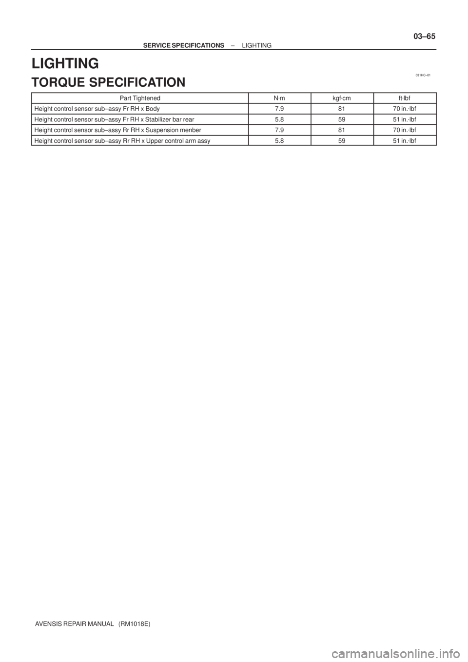
LIGHTING
TORQUE SPECIFICATION
Part TightenedN�mkgf�cmft�lbf
Height control sensor sub±assy Fr RH x Body7.98170 in.�lbf
Height control sensor sub±assy Fr RH x Stabilizer bar rear5.85951 in.�lbf
Height control sensor sub±assy Rr RH x Suspension menber7.98170 in.�lbf
Height control sensor sub±assy Rr RH x Upper control arm assy5.85951 in.�lbf
Page 175 of 5135

CLUTCH
SERVICE DATA
Pedal height from asphalt sheet
LHD steering position type
1CD±FTV engine type w/ intercooler
O")
030L1±03
± SERVICE SPECIFICATIONSCLUTCH
03±55
AVENSIS REPAIR MANUAL (RM1018E)
CLUTCH
SERVICE DATA
Pedal height from asphalt sheet
LHD steering position type
1CD±FTV engine type w/ intercooler
Others
154.0 ± 164.0 mm (6.063 ± 6.457 in.)
139.6 ± 149.6 mm (5.496 ± 5.890 in.)
Pedal height from asphalt sheet
RHD steering position type
1CD±FTV engine type w/ intercooler
Others
158.4 ± 168.4 mm (6.236 ± 6.630 in.)
148.4 ± 158.4 mm (5.843 ± 6.236 in.)
Clutch pedal free play5.0 ± 15.0 mm (0.197 ± 0591 in.)
Clutch pedal push rod play at pedal top1.0 ± 5.0 mm (0.039 ± 0.197 in.)
Slotted spring pin protrusion1.5 ± 3.5 mm (0.059 ± 0.138 in.)
Clutch release point from pedal full stroke end position25 mm (0.98 in.) or more
Clutch disc rivet head depth Maximum0.3 mm (0.012 in.)
Clutch disc assy runout Minimum0.8 mm (0.031 in.)
Diaphragm spring finger wear Maximum depth:
Maximum width:0.5 mm (0.020 in.)
6.0 mm (0.236 in.)
Flywheel sub±assy runout Maximum0.1 mm (0.004 in.)
Diaphragm tip alignment Maximum0.5 mm (0.020 in.)
Page 2288 of 5135

A09569
Measuring Tip
Protrusion Hight
± ENGINE MECHANICALCYLINDER HEAD GASKET (1CD±FTV)
14±335
AVENSIS REPAIR MANUAL (RM1018E)
(b) Lift")
A61194
Pry
A09555
Measuring Point
16 mm (0.63 in.)
A09569
Measuring Tip
Protrusion Hight
± ENGINE MECHANICALCYLINDER HEAD GASKET (1CD±FTV)
14±335
AVENSIS REPAIR MANUAL (RM1018E)
(b) Lift the cylinder head from the dowels on the cylinder
block, and place the cylinder head on wooden blocks on
a work bench.
NOTICE:
Be careful not to damage the contact surfaces of the cylin-
der head and cylinder block.
HINT:
If the cylinder head is lift off, pry between the cylinder head and
cylinder block with a screwdriver.
67. REMOVE CYLINDER HEAD GASKET
68. INSPECT CYLINDER HEAD SET BOLT
(a) Using vernier calipers, measure the tension portion diam-
eter of the bolts.
Standard outside diameter:
10.75 to 11.00 mm (0.4232 to 0.4331 in.)
Minimum outside diameter: 10.40 mm (0.4094 in.)
If the diameter is less than minimum, replace the bolt.
69. INSTALL CYLINDER HEAD GASKET
(a) Measure protrusion height of the piston heads.
(1) Clean the cylinder block with solvent.
(2) Set the piston to be measured to slightly before
TDC.
(3) Place a dial indicator on the cylinder block, and cali-
brate the dial indicator at 0 mm (0 in.).
HINT:
�Place measuring tip of the dial indicator as shown in the
illustration.
�Make sure that the measuring tip is square to the cylinder
block gasket and the piston head when measuring.
(4) Find the most overhung position of the piston head
by slowly turning the crankshaft clockwise and
counterclockwise.

BRAKE
SERVICE DATA
Brake pedal height (from asphalt sheet) RHD:
LHD:
M/T
A/T142.5 ± 152.5 mm (5.610 ± 6.004 in.)
148")