Page 3833 of 5135

A09543
SSTSST
A09541
A09540
Sharp 6 mm
Reamer 14±28
± ENGINE MECHANICALCYLINDER HEAD ASSY (1CD±FTV)
1CD±FTV ENGINE REPAIR MANUAL (RM927E)
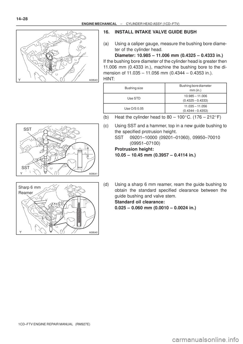
16. INSTALL INTAKE VALVE GUIDE BUSH
(a) Using a caliper gauge, measure the bushing bore diame-
ter of the cylinder head.
Diameter: 10.985 ± 11.006 mm (0.4325 ± 0.4333 in.)
If the bushing bore diameter of the cylinder head is greater then
11.006 mm (0.4333 in.), machine the bushing bore to the di-
mension of 11.035 ± 11.056 mm (0.4344 ± 0.4353 in.).
HINT:
Bushing sizeBushing bore diameter
mm (in.)
Use STD10.985 ± 11.006
(0.4325 ± 0.4333)
Use O/S 0.0511.035 ± 11.056
(0.4344 ± 0.4353)
(b) Heat the cylinder head to 80 ± 100�C. (176 ± 212�F)
(c) Using SST and a hammer, top in a new guide bushing to
the specified protrusion height.
SST 09201±10000 (09201±01060), 09950±70010
(09951±07100)
Protrusion height:
10.05 ± 10.45 mm (0.3957 ± 0.4114 in.)
(d) Using a sharp 6 mm reamer, ream the guide bushing to
obtain the standard specified clearance between the
guide bushing and valve stem.
Standard oil clearance:
0.025 ± 0.060 mm (0.0010 ± 0.0024 in.)
Page 3834 of 5135

A56676
A56677
SST
A56678
Sharp 6 mm
Reamer
± ENGINE MECHANICALCYLINDER HEAD ASSY (1CD±FTV)
14±29
1CD±FTV ENGINE REPAIR MANUAL (RM927E)
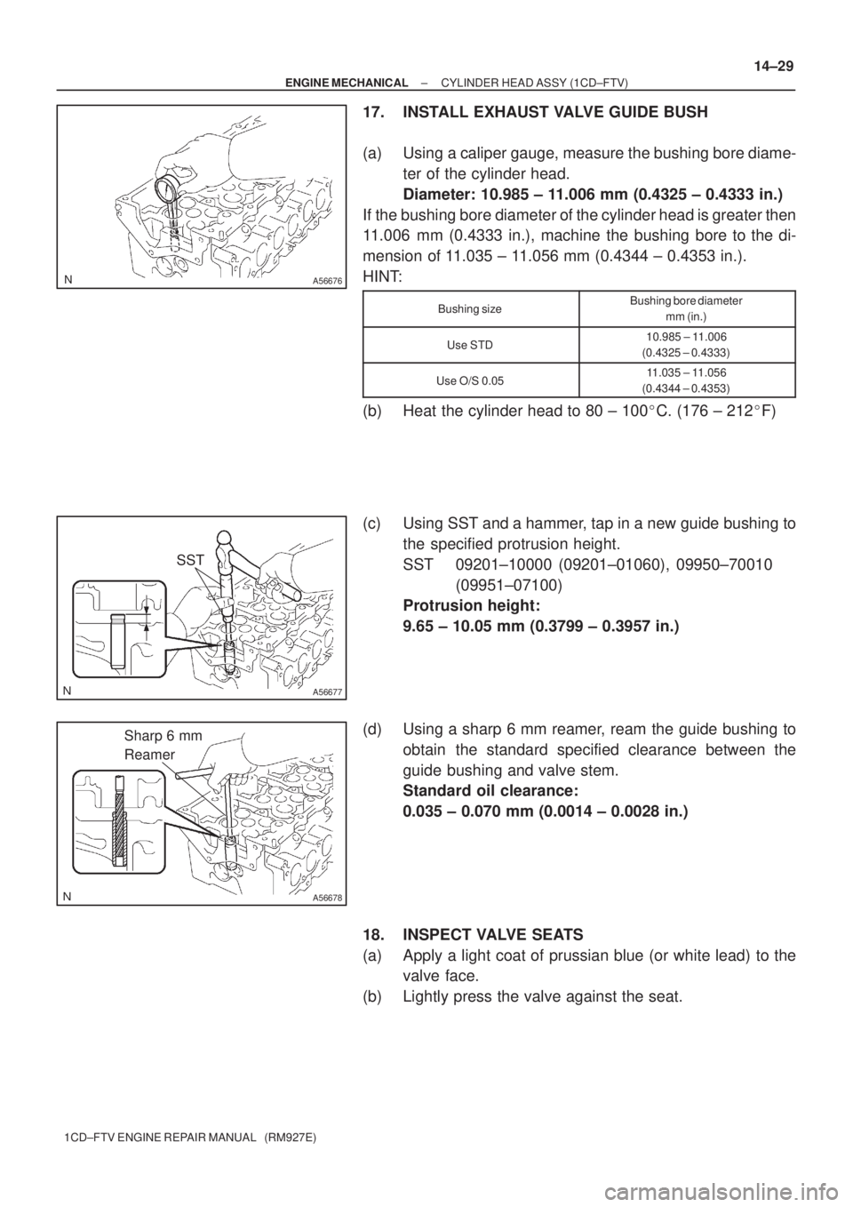
17. INSTALL EXHAUST VALVE GUIDE BUSH
(a) Using a caliper gauge, measure the bushing bore diame-
ter of the cylinder head.
Diameter: 10.985 ± 11.006 mm (0.4325 ± 0.4333 in.)
If the bushing bore diameter of the cylinder head is greater then
11.006 mm (0.4333 in.), machine the bushing bore to the di-
mension of 11.035 ± 11.056 mm (0.4344 ± 0.4353 in.).
HINT:
Bushing sizeBushing bore diameter
mm (in.)
Use STD10.985 ± 11.006
(0.4325 ± 0.4333)
Use O/S 0.0511.035 ± 11.056
(0.4344 ± 0.4353)
(b) Heat the cylinder head to 80 ± 100�C. (176 ± 212�F)
(c) Using SST and a hammer, tap in a new guide bushing to
the specified protrusion height.
SST 09201±10000 (09201±01060), 09950±70010
(09951±07100)
Protrusion height:
9.65 ± 10.05 mm (0.3799 ± 0.3957 in.)
(d) Using a sharp 6 mm reamer, ream the guide bushing to
obtain the standard specified clearance between the
guide bushing and valve stem.
Standard oil clearance:
0.035 ± 0.070 mm (0.0014 ± 0.0028 in.)
18. INSPECT VALVE SEATS
(a) Apply a light coat of prussian blue (or white lead) to the
valve face.
(b) Lightly press the valve against the seat.
Page 3837 of 5135

A09550
A09551
A09552
A09546
Plastigage
A09557
14±32
± ENGINE MECHANICALCYLINDER HEAD ASSY (1CD±FTV)
1CD±FTV ENGINE REPAIR MANUAL (RM927E)
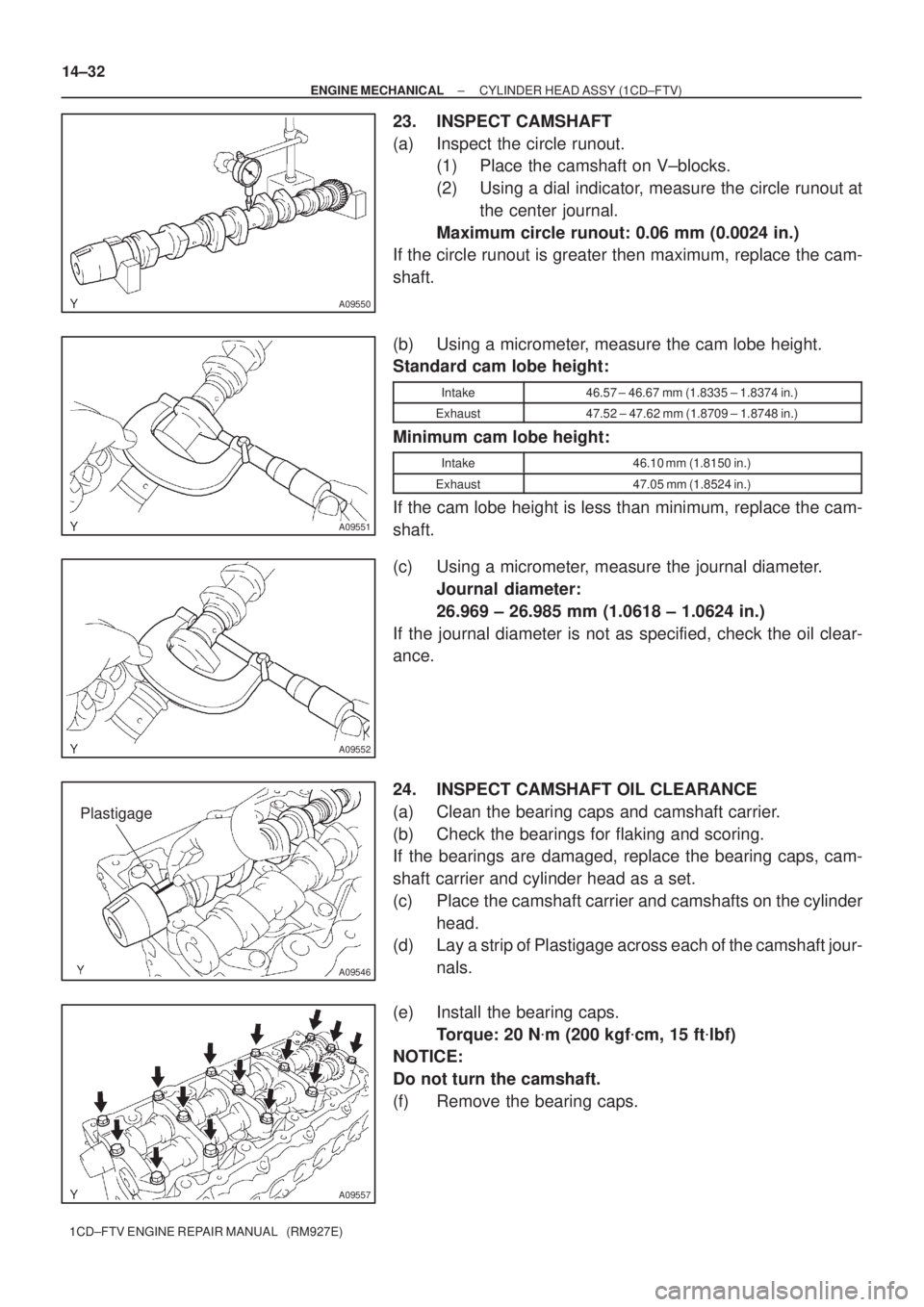
23. INSPECT CAMSHAFT
(a) Inspect the circle runout.
(1) Place the camshaft on V±blocks.
(2) Using a dial indicator, measure the circle runout at
the center journal.
Maximum circle runout: 0.06 mm (0.0024 in.)
If the circle runout is greater then maximum, replace the cam-
shaft.
(b) Using a micrometer, measure the cam lobe height.
Standard cam lobe height:
Intake46.57 ± 46.67 mm (1.8335 ± 1.8374 in.)
Exhaust47.52 ± 47.62 mm (1.8709 ± 1.8748 in.)
Minimum cam lobe height:
Intake46.10 mm (1.8150 in.)
Exhaust47.05 mm (1.8524 in.)
If the cam lobe height is less than minimum, replace the cam-
shaft.
(c) Using a micrometer, measure the journal diameter.
Journal diameter:
26.969 ± 26.985 mm (1.0618 ± 1.0624 in.)
If the journal diameter is not as specified, check the oil clear-
ance.
24. INSPECT CAMSHAFT OIL CLEARANCE
(a) Clean the bearing caps and camshaft carrier.
(b) Check the bearings for flaking and scoring.
If the bearings are damaged, replace the bearing caps, cam-
shaft carrier and cylinder head as a set.
(c) Place the camshaft carrier and camshafts on the cylinder
head.
(d) Lay a strip of Plastigage across each of the camshaft jour-
nals.
(e) Install the bearing caps.
Torque: 20 N�m (200 kgf�cm, 15 ft�lbf)
NOTICE:
Do not turn the camshaft.
(f) Remove the bearing caps.
Page 3840 of 5135
A56681
Intake Side: Upper Side:
Protrusion Height: 3 mm
11 m m8 mm
12.5 mm8 mmProtrusion Height: 3 mm
A56682
Upper Side:
11 m m Front Side:
16 mm
7 mm
7 mm
Protrusion Height: 11 mm Protrusion Height: 6 mm
± ENGINE MECHANICALCYLINDER HEAD ASSY (1CD±FTV)
14±35
1CD±FTV ENGINE REPAIR MANUAL (RM927E)
28. INSTALL RING PIN
(a) Using a plastic±faced hammer, tap in new ring pins to the
specified protrusion height.
29. INSTALL STRAIGHT PIN
(a) Using a plastic±faced hammer, tap in the straight pin.
Page 4030 of 5135
A87940
Cylinder Head Side: Lower Side:
Front Side:
A
11 mm (0.433 in.)
20 mm
(0.787 in.)
14 mm (0.55 in.) 8mm
(0.315 in.)
AAA
B B
Protrusion Height: 5.0 mm (0.197 in.)
Protrusion Height: 13 mm (0.512 in.)
BA 14−56
− ENGINE MECHANICALCYLINDER BLOCK ASSY (1CD−FTV)(From September,
2003)
1CD−FTV ENGINE REPAIR MANUAL (RM1046E)
22. INSTALL RING PIN
(a) Using a plastic−faced hammer, tap in new ring pins until
their protrusion heights are as specified.
Page 4618 of 5135

A09555
Measuring Point
16 mm (0.63 in.)
A09569
Measuring Tip
Protrusion Height
A09571
Front
X Measuring Point 14−170
− ENGINE MECHANICALCYLINDER HEAD GASKET (1CD−FTV)(From
September, 2003)
AVENSIS Supplement (RM1045E)
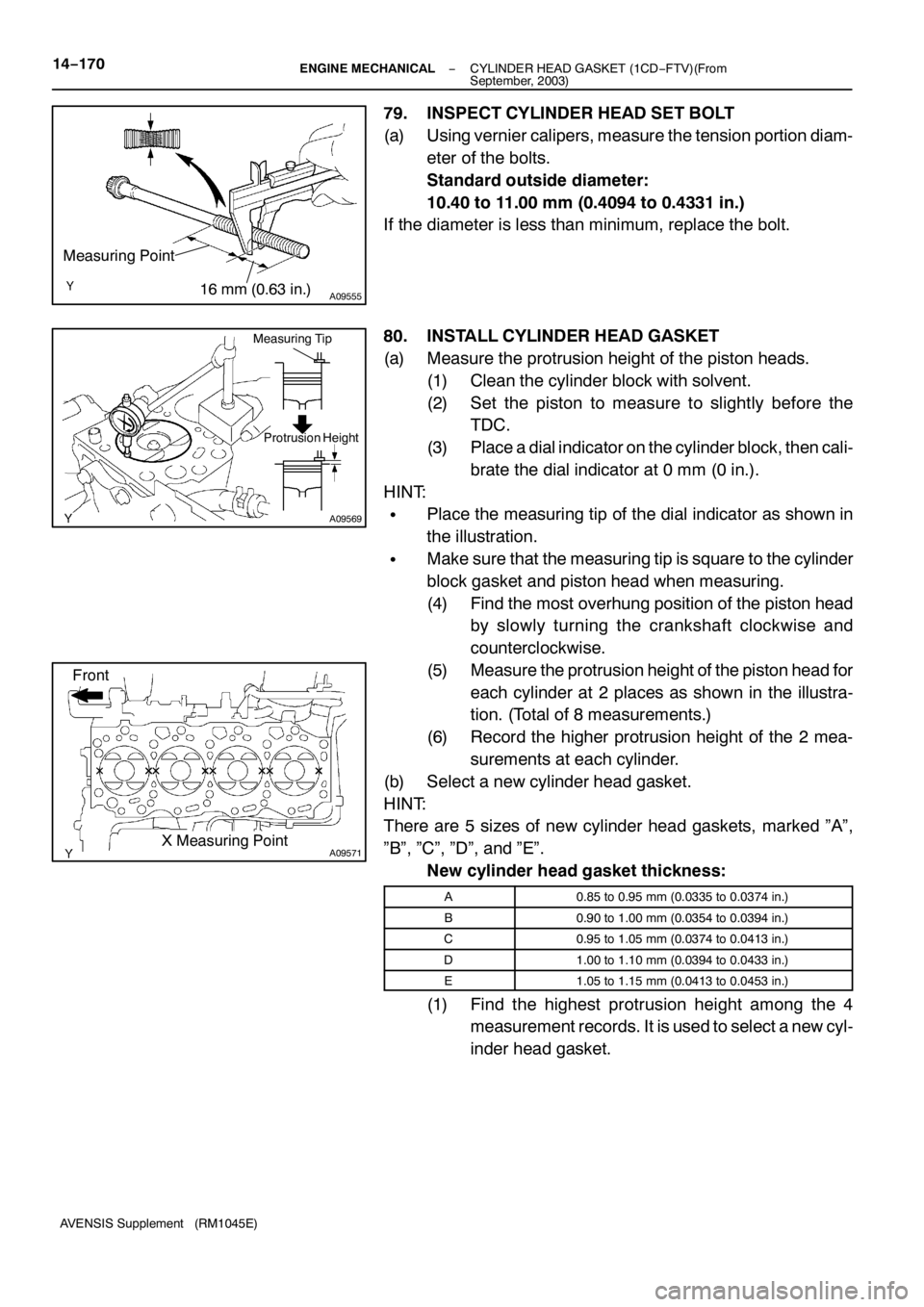
79. INSPECT CYLINDER HEAD SET BOLT
(a) Using vernier calipers, measure the tension portion diam-
eter of the bolts.
Standard outside diameter:
10.40 to 11.00 mm (0.4094 to 0.4331 in.)
If the diameter is less than minimum, replace the bolt.
80. INSTALL CYLINDER HEAD GASKET
(a) Measure the protrusion height of the piston heads.
(1) Clean the cylinder block with solvent.
(2) Set the piston to measure to slightly before the
TDC.
(3) Place a dial indicator on the cylinder block, then cali-
brate the dial indicator at 0 mm (0 in.).
HINT:
SPlace the measuring tip of the dial indicator as shown in
the illustration.
SMake sure that the measuring tip is square to the cylinder
block gasket and piston head when measuring.
(4) Find the most overhung position of the piston head
by slowly turning the crankshaft clockwise and
counterclockwise.
(5) Measure the protrusion height of the piston head for
each cylinder at 2 places as shown in the illustra-
tion. (Total of 8 measurements.)
(6) Record the higher protrusion height of the 2 mea-
surements at each cylinder.
(b) Select a new cylinder head gasket.
HINT:
There are 5 sizes of new cylinder head gaskets, marked ”A”,
”B”, ”C”, ”D”, and ”E”.
New cylinder head gasket thickness:
A0.85 to 0.95 mm (0.0335 to 0.0374 in.)
B0.90 to 1.00 mm (0.0354 to 0.0394 in.)
C0.95 to 1.05 mm (0.0374 to 0.0413 in.)
D1.00 to 1.10 mm (0.0394 to 0.0433 in.)
E1.05 to 1.15 mm (0.0413 to 0.0453 in.)
(1) Find the highest protrusion height among the 4
measurement records. It is used to select a new cyl-
inder head gasket.
Page 4653 of 5135
A79184
A85928
A61177
A59793
A59792
14−11 2− ENGINE MECHANICALPARTIAL ENGINE ASSY (1CD−FTV)(From September,
2003)
AVENSIS Supplement (RM1045E)
46. REMOVE ENGINE ASSEMBLY WITH TRANSAXLE
(a) Disconnect the height control sensor connector (with dis-
charge head lamp).
(b) Set the engine lifter.
(c) Remove the 3 bolts, 3 nuts and engine mounting insulator
sub−assembly RH.
(d) Remove the through bolt and nut, then detach the engine
mounting insulator LH from the vehicle.
(e) Remove the 8 bolts and front suspension member brace
rear RH and LH.
(f) Remove the 2 bolts and 2 nuts.
(g) Carefully remove the engine together with the transaxle
from the vehicle.
Page 4730 of 5135
− BRAKEBRAKE BOOSTER ASSY (RHD) (2AZ−FSE)
32−7
AVENSIS Supplement (RM1045E)
20. INSTALL ENGINE COVER NO.1
21. INSTALL FRONT WHEEL RH
Torque:103 N�m(1,050 kgf�cm, 76 ft�lbf)
22. FILL RESERVOIR WITH BRAKE FLUID
23. BLEED MASTER CYLINDER
SST 09023−00100
24. BLEED BRAKE LINE
25. CHECK AND ADJUST BRAKE PEDAL HEIGHT
26. CHECK PEDAL FREE PLAY
27. CHECK PEDAL RESERVE DISTANCE
28. CHECK FLUID LEVEL IN RESERVOIR
29. CHECK BRAKE FLUID LEAKAGE