Page 3097 of 5135
650T4±01
I35240
I35240
A
B
A
±
LIGHTING HEIGHT CONTROL SENSOR SUB±ASSY REAR RH
65±29
AVENSIS REPAIR MANUAL (RM1018E)
HEIGHT CONTROL SENSOR SUB±ASSY REAR RH
REPLACEMENT
1.REMOVE HEIGHT CONTROL SENSOR SUB±ASSY
REAR RH
(a)Disconnect the connector.
(b)Remove the 2 bolts, the nut and height control sensor sub±assy rear RH.
2.INSTALL HEIGHT CONTROL SENSOR SUB±ASSY REAR RH
(a)Install the height control sensor sub±assy rear RH with the 2 bolts and the nut.
Torque:
Bolt (A): 7.9 N �m (81 kgf �cm, 70 in. �lbf)
Nut (B): 5.8 N �m (59 kgf �cm, 51 in. �lbf)
(b)Connect the connector.
3.HEADLIGHT AIM ONLY (See page 65±19)
Page 3098 of 5135
650T3±01
I35231
I35231
AB
A
65±28
±
LIGHTING HEIGHT CONTROL SENSOR SUB±ASSY FR RH
AVENSIS REPAIR MANUAL (RM1018E)
HEIGHT CONTROL SENSOR SUB±ASSY FR RH
REPLACEMENT
1.REMOVE HEIGHT CONTROL SENSOR SUB±ASSY FR RH
(a)Disconnect the connector.
(b)Remove the 3 nuts and height control sensor sub±assy front RH.
2.INSTALL HEIGHT CONTROL SENSOR SUB±ASSY FR RH
(a)Install the height control sensor sub±assy front RH with the 3 nuts.
Torque:
A: 7.9 N �m (81 kgf �cm, 70 in. �lbf)
B: 5.8 N �m (59 kgf �cm, 51 in. �lbf)
(b)Connect the connector.
3.HEADLIGHT AIM ONLY (See page 65±19)
Page 3106 of 5135

ADJUSTMENT
1. HEADLIGHT AIM ONLY
HINT:
�Perform aiming adjustment with Low�")
650SV±01
I33423
V LH LineV RH LineV Line
Ground
H Line
± LIGHTINGHEADLAMP UNIT LH
65±19
AVENSIS REPAIR MANUAL (RM1018E)
ADJUSTMENT
1. HEADLIGHT AIM ONLY
HINT:
�Perform aiming adjustment with Low±beam.
�Since the Low±beam light and the High±beam light is a
unit, if aiming on either side is connect, the other side
should also be connect.
However, check both beams just to make sure.
(a) Prepare vehicle in the following conditions.
�Check that any damage or deformation does not exist on
the body around the headlights.
�Fuel tank is full.
�The tire inflation pressure is at the specified level.
�Vehicle is parked at a level surface.
�A person having an average weight sits in the driver's
seat.
�Vehicle is bounced up and down to stabilize the suspen-
sion to the normal position.
(b) Prepare a thick white paper (Draw base lines).
HINT:
�Stand the paper perpendicular as against a wall.
�The base lines differ for ºLow±beam inspectionº and
ºHigh±beam inspectionº.
(1) V line (Vehicle Center position)
Draw a vertical line down the center of the paper in
order to align it with the center of the vehicle.
(2) H line (Headlight height)
Draw horizontal line across the paper at the same
height from the ground as the center mark for the
Low±beam lights.
(3) V LH line, V RH line (Center mark position of right
and left headlights)
Draw vertical lines, for left & right, at the same posi-
tion as the center mark for the Low±beam lights.
HINT:
Follow the same procedures when adjusting the High±beam
lights.
Page 3107 of 5135

I37308
Low Beam:V LH Line
V RH Line
30mm
(1.18 in.)84 mm
(3.3 in.)
H Line6mm
(0.23 in.)
I37102
High Beam:V LH Line
V RH Line
H Line
I35802Adjusting B")
I35248
V LH Line
V RH Line
V Line90�
3 m (9.84 ft)
I37308
Low Beam:V LH Line
V RH Line
30mm
(1.18 in.)84 mm
(3.3 in.)
H Line6mm
(0.23 in.)
I37102
High Beam:V LH Line
V RH Line
H Line
I35802Adjusting Bolt A
Adjusting Bolt B
65±20
± LIGHTINGHEADLAMP UNIT LH
AVENSIS REPAIR MANUAL (RM1018E)
(c) Check the headlight aiming.
(1) Align the paper with the center of the vehicle.
�Make a distance of 3 m ( 9.84 ft) between the head-
lights and the paper, and put the paper against a
wall with the H line being at the same height as the
center mark.
�Align the center of the vehicle with the V line on the
paper, and ensure that the paper is at a 90� angle
in accordance to the V line.
(2) Start the engine.
(3) Turn on the headlights and check that the aim is with
in the specified valves shown in the illustration.
NOTICE:
�When covering the headlights, finish it within 3 mi-
nuites.
�The headlight lens is made of synthetic resin, so it is
easily.
HINT:
When checking the aiming of the High±beam, shut off the Low±
beam or disconnect the Low±beam headlight connector.
(d) Adjust the aim in the vertical direction:
Using a screwdriver, adjust the headlight aim within the
specified range by turning the aiming screw A.
NOTICE:
�Adjust the headlight aim by turning the screw in the
tightening direction.
�When the screw is tightened excessively, loosen it
once and re±tighten it to adjust the headlight aim.
HINT:
The optical axis aim moves downward when turning the screw-
driver clockwise, and it moves upward when turning the screw-
driver counterclockwise.
(e) Adjust the aim in the horizontal direction:
Using a screwdriver, adjust the headlight aim within the
specified range by turning the aiming screw B.
NOTICE:
�Adjust the headlight aim by turning the screw in the
tightening direction.
�When the screw is tightened excessively, loosen it
once and re±tighten it to adjust the headlight aim.
Page 3117 of 5135
E68134
20��6�
0� +45�
±45�(Low) (High)
E68135
21.3��6� 0�
+45� ±45�(Low)
(High)
65±14
± LIGHTINGLIGHTING SYSTEM
AVENSIS REPAIR MANUAL (RM1018E)
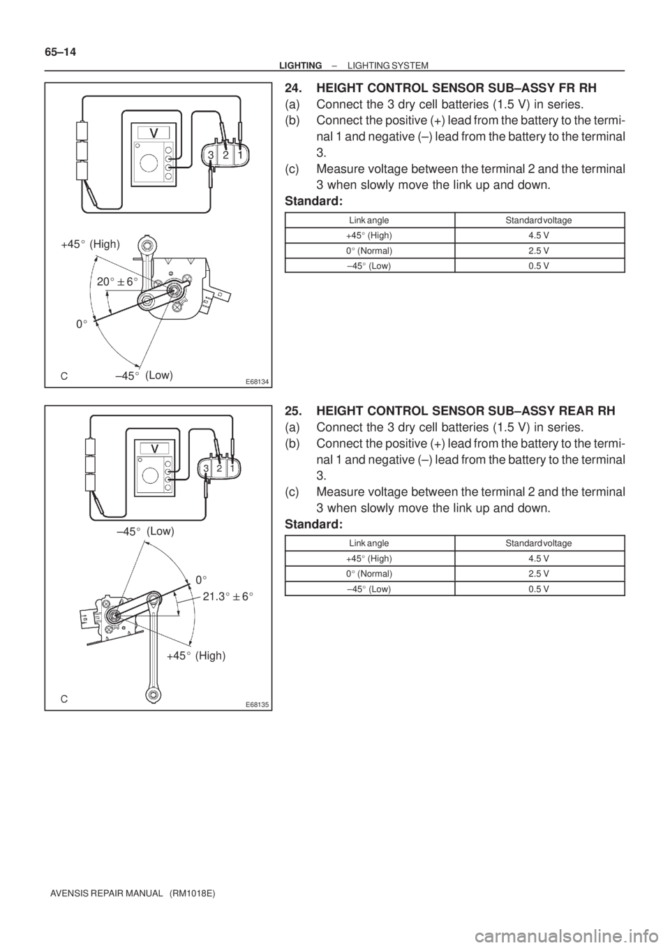
24. HEIGHT CONTROL SENSOR SUB±ASSY FR RH
(a) Connect the 3 dry cell batteries (1.5 V) in series.
(b) Connect the positive (+) lead from the battery to the termi-
nal 1 and negative (±) lead from the battery to the terminal
3.
(c) Measure voltage between the terminal 2 and the terminal
3 when slowly move the link up and down.
Standard:
Link angleStandard voltage
+45� (High)4.5 V
0� (Normal)2.5 V
±45� (Low)0.5 V
25. HEIGHT CONTROL SENSOR SUB±ASSY REAR RH
(a) Connect the 3 dry cell batteries (1.5 V) in series.
(b) Connect the positive (+) lead from the battery to the termi-
nal 1 and negative (±) lead from the battery to the terminal
3.
(c) Measure voltage between the terminal 2 and the terminal
3 when slowly move the link up and down.
Standard:
Link angleStandard voltage
+45� (High)4.5 V
0� (Normal)2.5 V
±45� (Low)0.5 V
Page 3369 of 5135

(2)Adjust the clearance by moving the hood, so that it
will be in the standard range.
Standard range (A)")
B66963
A
Aligned
B66964
B62401
±
ENGINE HOOD/DOOR HOOD
75±3
AVENSIS REPAIR MANUAL (RM1018E)
(2)Adjust the clearance by moving the hood, so that it
will be in the standard range.
Standard range (A): 3.5 � 1.5 mm (0.138 � 0.059 in.)
(3)Tighten the hood side hinge bolts after the adjust- ment.
Torque: 13 N �m (133 kgf �cm, 10 ft �lbf)
(b)Adjust the height of the hood front end using the cushion rubber.
(1)Adjust the cushion rubber so that the hood and thefender will be aligned.
HINT:
The cushion rubber goes up and down by turning it.
(c)Adjust the hood lock.
(1)Using a clip remover, remove the 6 clips and frontend seal.
(2)Remove the retainer and battery service hole cover.
(3)Using a clip remover, remove the 3 clips and radia-
tor cover.
(4)Using a clip remover, remove the 3 clips and engine room side cover RH.
(5)Remove the front bumper (See page 76±3).
(6) Adjust the hood lock position by moving the striker, so that the striker can enter smoothly.
(7) Tighten the hood lock bolts after the adjustment.
Torque: 8.0 N �m (82 kgf �cm, 71 in. �lbf)
Page 3462 of 5135

TERMS
ABBREVIATIONS USED IN THIS MANUAL
AbbreviationsMeaning
ABSAnti±Lock Brake System
A/CAir Conditioner
ACAlternating")
010B9±09
± INTRODUCTIONTERMS
01±7
1AZ±FSE ENGINE REPAIR MANUAL (RM1019E)
TERMS
ABBREVIATIONS USED IN THIS MANUAL
AbbreviationsMeaning
ABSAnti±Lock Brake System
A/CAir Conditioner
ACAlternating Current
ACCAccessory
ACISAcoustic Control Induction System
ACSDAutomatic Cold Start Device
A.D.D.Automatic Disconnecting Differential
A/FAir±Fuel Ratio
AHCActive Height Control Suspension
ALRAutomatic Locking Retractor
ALTAlternator
AMPAmplifier
ANTAntenna
Approx.Approximately
ASSYAssembly
A/T, ATMAutomatic Transmission (Transaxle)
AT FAutomatic Transmission Fluid
AUTOAutomatic
AUXAuxiliary
AV GAverage
AV SAdaptive Variable Suspension
B+Battery Voltage
BABrake Assist
BACSBoost Altitude Compensation System
BATBattery
BDCBottom Dead Center
B/LBi±Level
B/SBore±Stroke Ratio
BTDCBefore Top Dead Center
BVSVBimetallic Vacuum Switching Valve
CBCircuit Breaker
CCoCatalytic Converter For Oxidation
CDCompact Disc
CFCornering Force
CGCenter Of Gravity
CHChannel
CKDComplete Knock Down
COMB.Combination
CPECoupe
CPSCombustion Pressure Sensor
CPUCentral Processing Unit
CRSChild Restraint System
CTRCenter
C/VCheck Valve
CVControl Valve
CWCurb Weight
DCDirect Current
DEFDefogger
Page 3464 of 5135
Abbreviations Meaning
HIHigh
HIDHigh Intensity Discharge (Head Lamp)
HSGHousing
HTHard Top
HWSHeated Windshield System
ICIntegrated")
± INTRODUCTIONTERMS
01±9
1AZ±FSE ENGINE REPAIR MANUAL (RM1019E)Abbreviations Meaning
HIHigh
HIDHigh Intensity Discharge (Head Lamp)
HSGHousing
HTHard Top
HWSHeated Windshield System
ICIntegrated Circuit
IDIIndirect Diesel Injection
IFSIndependent Front Suspension
IGIgnition
IIAIntegrated Ignition Assembly
INIntake (Manifold, Valve)
INTIntermittent
I/PInstrument Panel
IRSIndependent Rear Suspension
ISCIdle Speed Control
J/BJunction Block
J/CJunction Connector
KDKick±Down
LANLocal Area Network
LBLiftback
LCDLiquid Crystal Display
LEDLight Emitting Diode
LHLeft±Hand
LHDLeft±Hand Drive
L/H/WLength, Height, Width
LLCLong±Life Coolant
LNGLiquified Natural Gas
LOLow
LPGLiquified Petroleum Gas
LSDLimited Slip Differential
LSP & PVLoad Sensing Proportioning And Bypass Valve
LSPVLoad Sensing Proportioning Valve
MAPManifold Absolute Pressure
MAX.Maximum
MICMicrophone
MILMalfunction Indicator Lamp
MIN.Minimum
MG1Motor Generator No.1
MG2Motor Generator No.2
MPMultipurpose
MPIMultipoint Electronic Injection
MPXMultiplex Communication System
M/T, MTMManual Transmission (Transaxle)
MTMount
MTGMounting
NNeutral
NANatural Aspiration
No.Number
O2SOxygen Sensor
O/DOverdrive
OEMOriginal Equipment Manufacturing

HEIGHT CONTROL SENSOR SUB±ASSY REAR RH
REPLACEMENT
1.REMOVE HEIGHT CONTROL S")

HEIGHT CONTROL SENSOR SUB±ASSY FR RH
REPLACEMENT
1.REMOVE HEIGHT CONTROL SENSOR")