Page 15 of 5135
± INTRODUCTIONTERMS
01±41
AVENSIS REPAIR MANUAL (RM1018E)Abbreviations Meaning
TFTToyota Free±Tronic
TISTotal Information System For Vehicle Development
T/MTransmission
TMCTOYOTA Motor Corporation
TMMKTOYOTA Motor Manufacturing Kentucky, Inc.
TRCTraction Control System
TURBOTurbocharge
TWCThree±Way Catalyst
U/DUnderdrive
U/SUndersize
VCVVacuum Control Valve
VENTVentilator
VINVehicle Identification Number
VPSVariable Power Steering
VSCVehicle Stability Control
VSVVacuum Switching Valve
VTVVacuum Transmitting Valve
VVT±iVariable Valve Timing±intelligent
w/With
WGNWagon
W/HWire Harness
w/oWithout
WU±TWCWarm Up Three±way Catalytic Converter
WU±OCWarm Up Oxidation Catalytic Converter
1stFirst
2ndSecond
2WDTwo Wheel Drive Vehicle (4 x 2)
3rdThird
4thFourth
4WDFour Wheel Drive Vehicle (4 x 4)
4WSFour Wheel Steering System
5thFifth
Page 46 of 5135
D25081
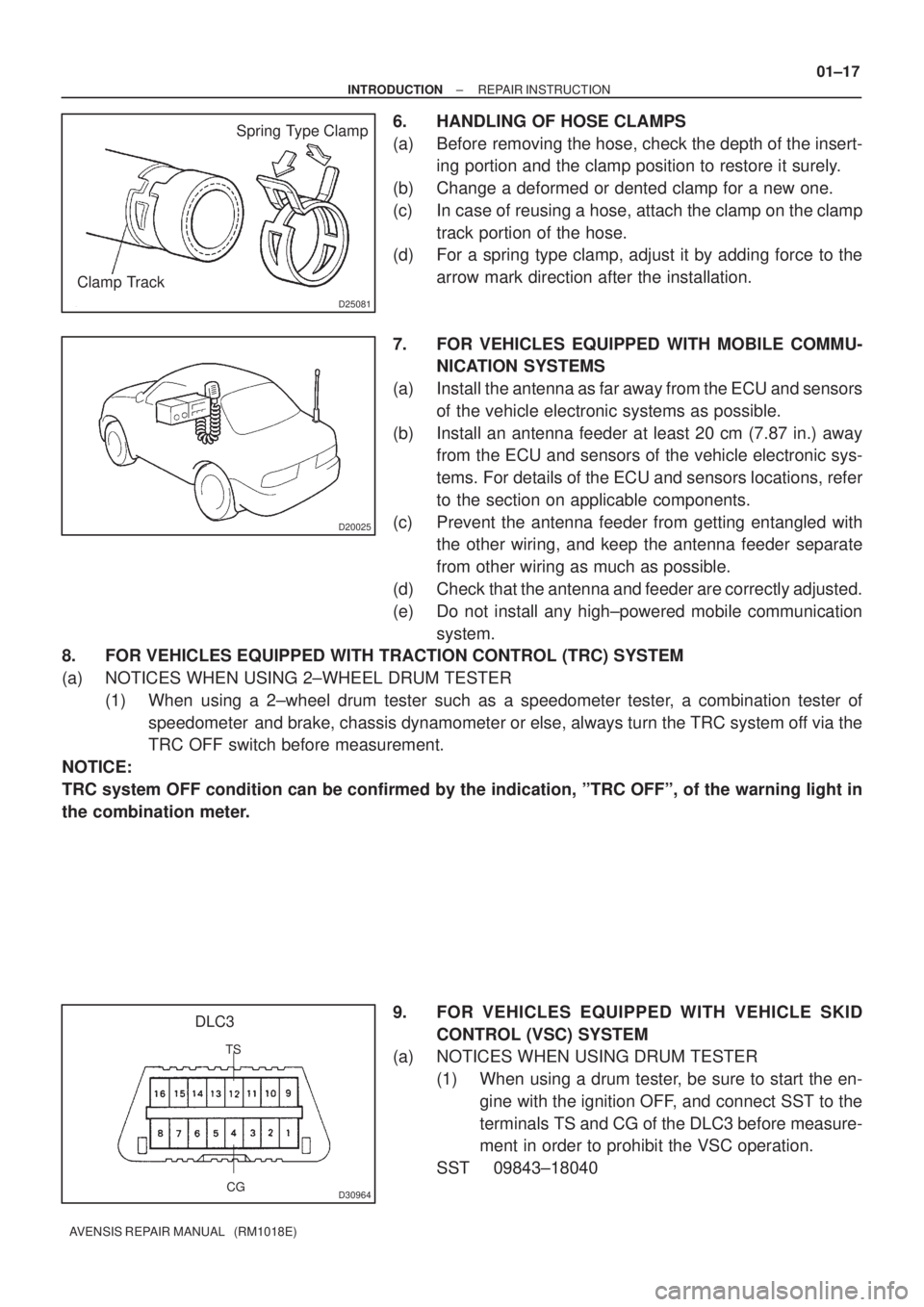
Spring Type Clamp
Clamp Track
D20025
CG
DLC3
TS
D30964
± INTRODUCTIONREPAIR INSTRUCTION
01±17
AVENSIS REPAIR MANUAL (RM1018E)
6. HANDLING OF HOSE CLAMPS
(a) Before removing the hose, check the depth of the insert-
ing portion and the clamp position to restore it surely.
(b) Change a deformed or dented clamp for a new one.
(c) In case of reusing a hose, attach the clamp on the clamp
track portion of the hose.
(d) For a spring type clamp, adjust it by adding force to the
arrow mark direction after the installation.
7. FOR VEHICLES EQUIPPED WITH MOBILE COMMU-
NICATION SYSTEMS
(a) Install the antenna as far away from the ECU and sensors
of the vehicle electronic systems as possible.
(b) Install an antenna feeder at least 20 cm (7.87 in.) away
from the ECU and sensors of the vehicle electronic sys-
tems. For details of the ECU and sensors locations, refer
to the section on applicable components.
(c) Prevent the antenna feeder from getting entangled with
the other wiring, and keep the antenna feeder separate
from other wiring as much as possible.
(d) Check that the antenna and feeder are correctly adjusted.
(e) Do not install any high±powered mobile communication
system.
8. FOR VEHICLES EQUIPPED WITH TRACTION CONTROL (TRC) SYSTEM
(a) NOTICES WHEN USING 2±WHEEL DRUM TESTER
(1) When using a 2±wheel drum tester such as a speedometer tester, a combination tester of
speedometer and brake, chassis dynamometer or else, always turn the TRC system off via the
TRC OFF switch before measurement.
NOTICE:
TRC system OFF condition can be confirmed by the indication, ºTRC OFFº, of the warning light in
the combination meter.
9. FOR VEHICLES EQUIPPED WITH VEHICLE SKID
CONTROL (VSC) SYSTEM
(a) NOTICES WHEN USING DRUM TESTER
(1) When using a drum tester, be sure to start the en-
gine with the ignition OFF, and connect SST to the
terminals TS and CG of the DLC3 before measure-
ment in order to prohibit the VSC operation.
SST 09843±18040
Page 852 of 5135
±
DIAGNOSTIC SABS WITH EBD & BA & TRC & VSC SYSTEM
05±807
AVENSIS RE PAIR MANUAL (RM1018E)
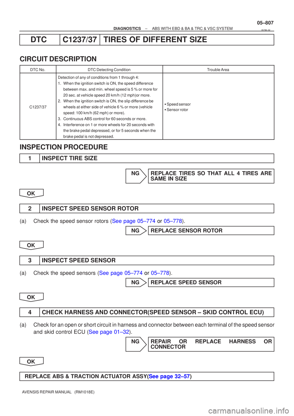
DT C C1237/3 7TIRE S OF DIFFERENT SIZE
CIRCUI T DESCRIPTION
DT C No.DTC Detecting ConditionTrouble Area
C1237/37
Detection of any of conditions from 1 through 4:
1. When the ignition switch is ON, the speed di fference
between max. and min. wheel speed is 5 % or more for
20 sec. at vehicle speed 20 km/h (12 mph)or more.
2 . When the ignition switch is ON, the slip di fference be
wheels at either side of vehicle 6 % or more (vehicle
speed: 100 km/h (62 mph) or more).
3 . Continuous ABS control for 60 seconds or more.
4 . Interference on 1 or more wheels for 20 seconds with
the brake pedal depressed, or for 5 seconds when the
brake pedal is not depressed.
�Speed sensor
� Senso rrotor
INSPECTIO N PROCEDURE
1 INSPEC T TIRE SIZE
N G REPLAC E TIRES SO TH AT ALL 4 TIRES ARE
SAM E IN SIZE
OK
2 INSPECT SPEED SENSOR RO TOR
(a ) Check the speed sensor rotors ( See page 05±774 or 05±778 ).
N G REPLACE SENSOR RO TOR
OK
3 INSPECT SPEED SENSOR
(a) Check the speed sensors ( See page 05±774 or 05±778 ).
N G REPLACE SPEED SENSOR
OK
4 CHECK HARNESS AND CONNEC TOR(SPEED SENSOR ± SKID CONTROL ECU)
(a ) Chec k for an open or short circuit in harness and connector between each terminal of the speed sensor
an d skid control ECU ( See page 01±32).
N G REPAIR OR REPLACE HARNESS OR
CONNEC TOR
OK
REPLAC E ABS & TRACTION ACTU ATOR ASSY( See page 32±57 )
05786±02
Page 854 of 5135
F45132
Battery
FL MAIN Skid Control ECU
with Actuator
B±G (*1)L (*1) 1
ALT
Engine Room R/B No.4 & Engine Room J/B No.4
1
4B
W±BS1
S1 10
9
+BM
12
1
2
GND1 GND2
S1 6
W±B W±B
*1: 1AZ±FSE
*2: 1CD±FTV EA4
L (*2)
W (*2)
2
12
331
1B1
VSC
ALT
Engine Room R/B No.3
Engine Room R/B No.1 &
Engine Room J/B No.1
B (*2)
B±G (*1) VSC
05±806
±
DIAGNOSTICS ABS WITH EBD & BA & TRC & VSC SYSTEM
AVENSIS REPAIR MANUAL (RM1018E)
WIRING DIAGRAM
INSPECTION PROCEDURE
1RECONFIRM DTC
(a)Check if other DTCs are detected (See page 05±756). YES REPAIR CIRCUIT INDICATED BY OUTPUTCODE
NO
REPLACE ABS & TRACTION ACTUATOR ASSY(See page 32±57)
Page 858 of 5135
05±804
±
DIAGNOSTICS ABS WITH EBD & BA & TRC & VSC SYSTEM
AVENSIS REPAIR MANUAL (RM1018E)
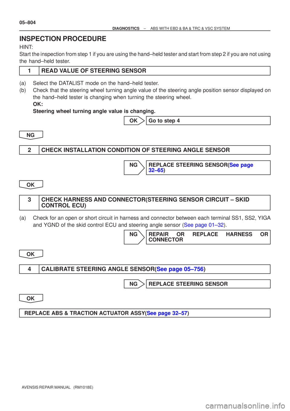
INSPECTION PROCEDURE
HINT:
Start the inspection from step 1 if you are using the hand±held tester and\
start from step 2 if you are not using
the hand±held tester.
1READ VALUE OF STEERING SENSOR
(a)Select the DATALIST mode on the hand±held tester.
(b)Check that the steering wheel turning angle value of the steering angle position sensor displayed on the hand±held tester is changing when turning the steering wheel.
OK:
Steering wheel turning angle value is changing.
OKGo to step 4
NG
2CHECK INSTALLATION CONDITION OF STEERING ANGLE SENSOR
NGREPLACE STEERING SENSOR(See page 32±65)
OK
3 CHECK HARNESS AND CONNECTOR(STEERING SENSOR CIRCUIT ± SKID CONTROL ECU)
(a) Check for an open or short circuit in harness and connector between each term\
inal SS1, SS2, YIGA
and YGND of the skid control ECU and steering angle sensor (See page 01±32).
NG REPAIR OR REPLACE HARNESS ORCONNECTOR
OK
4CALIBRATE STEERING ANGLE SENSOR(See page 05±756)
NG REPLACE STEERING SENSOR
OK
REPLACE ABS & TRACTION ACTUATOR ASSY(See page 32±57)
Page 860 of 5135
05±800
±
DIAGNOSTICS ABS WITH EBD & BA & TRC & VSC SYSTEM
AVENSIS REPAIR MANUAL (RM1018E)
INSPECTION PROCEDURE
1CHECK HARNESS AND CONNECTOR(ECM ± SKID CONTROL ECU)
(a)Check for an open or short circuit in harness and connector between each of t\
erminals ENG+, ENG±, TRC+, TRC± of the skid control ECU and the same one of the ECM (See page 01±32).
NG REPAIR OR REPLACE HARNESS ORCONNECTOR
OK
2 CHECK OPERATION OF MALFUNCTION INDICATOR
(a) Check the MIL. (1) The MIL comes on when the ignition switch is turned ON and the engine is\
not running.
NG CHECK AND REPLACE ECM
OK
CHECK AND REPLACE ABS & TRACTION ACTUATOR ASSY(See page 32±57)
Page 866 of 5135
C95217
±
DIAGNOSTICS ABS WITH EBD & BA & TRC & VSC SYSTEM
05±795
AVENSIS REPAIR MANUAL (RM1018E)
INSPECTION PROCEDURE
HINT:
Start the inspection from step 1 if you are using the hand±held tester and\
start from step 2 if you are not using
the hand±held tester.
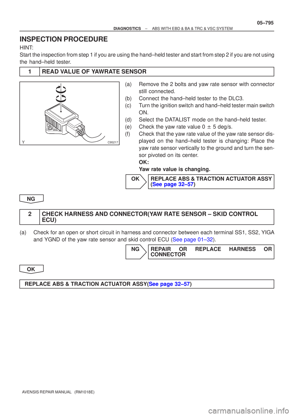
1READ VALUE OF YAWRATE SENSOR
(a)Remove the 2 bolts and yaw rate sensor with connector
still connected.
(b)Connect the hand±held tester to the DLC3.
(c)Turn the ignition switch and hand±held tester main switch ON.
(d)Select the DATALIST mode on the hand±held tester.
(e)Check the yaw rate value 0 � 5 deg/s.
(f)Check that the yaw rate value of the yaw rate sensor dis- played on the hand±held tester is changing: Place the
yaw rate sensor vertically to the ground and turn the sen-
sor pivoted on its center.
OK:
Yaw rate value is changing.
OKREPLACE ABS & TRACTION ACTUATOR ASSY (See page 32±57)
NG
2 CHECK HARNESS AND CONNECTOR(YAW RATE SENSOR ± SKID CONTROL ECU)
(a) Check for an open or short circuit in harness and connector between each term\
inal SS1, SS2, YIGA
and YGND of the yaw rate sensor and skid control ECU (See page 01±32).
NG REPAIR OR REPLACE HARNESS ORCONNECTOR
OK
REPLACE ABS & TRACTION ACTUATOR ASSY(See page 32±57)
Page 869 of 5135
C95216
05±792
±
DIAGNOSTICS ABS WITH EBD & BA & TRC & VSC SYSTEM
AVENSIS REPAIR MANUAL (RM1018E)
INSPECTION PROCEDURE
HINT:
Start the inspection from step 1 if you are using the hand±held tester and\
start from step 2 if you are not using
the hand±held tester.
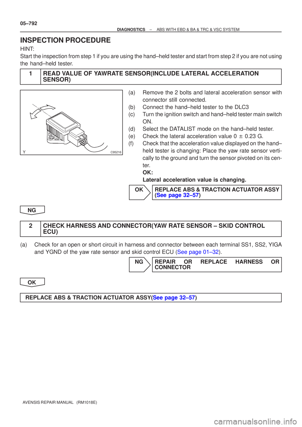
1READ VALUE OF YAWRATE SENSOR(INCLUDE LATERAL ACCELERATION SENSOR)
(a)Remove the 2 bolts and lateral acceleration sensor with
connector still connected.
(b)Connect the hand±held tester to the DLC3
(c)Turn the ignition switch and hand±held tester main switch ON.
(d)Select the DATALIST mode on the hand±held tester.
(e)Check the lateral acceleration value 0 � 0.23 G.
(f)Check that the acceleration value displayed on the hand±
held tester is changing: Place the yaw rate sensor verti-
cally to the ground and turn the sensor pivoted on its cen-
ter.
OK:
Lateral acceleration value is changing.
OKREPLACE ABS & TRACTION ACTUATOR ASSY (See page 32±57)
NG
2 CHECK HARNESS AND CONNECTOR(YAW RATE SENSOR ± SKID CONTROL ECU)
(a) Check for an open or short circuit in harness and connector between each term\
inal SS1, SS2, YIGA
and YGND of the yaw rate sensor and skid control ECU (See page 01±32).
NG REPAIR OR REPLACE HARNESS ORCONNECTOR
OK
REPLACE ABS & TRACTION ACTUATOR ASSY(See page 32±57)