Page 877 of 5135
F45132
Battery
FL MAIN Skid Control ECU
with Actuator
B±G (*1)R (*1) 1
ALTVSC
Engine Room R/B No.4 & Engine Room J/B No.4
1
4B
W±BS1
S1
10 5
+BS
12
1
2
GND1 GND2
S1 6
W±B W±B
*1: 1AZ±FSE
*2: 1CD±FTV EA4
R (*2)
W (*2)
2
12
331
1B1
ALT
Engine Room R/B No.3
Engine Room R/B No.1 &
Engine Room J/B No.1
B (*2)
B±G (*1) VSC
±
DIAGNOSTICS ABS WITH EBD & BA & TRC & VSC SYSTEM
05±783
AVENSIS REPAIR MANUAL (RM1018E)
WIRING DIAGRAM
INSPECTION PROCEDURE
1RECONFIRM DTC
(a)Check if other DTCs are detected (See page 05±756).
YES REPAIR CIRCUIT INDICATED BY OUTPUTCODE
NO
REPLACE ABS & TRACTION ACTUATOR ASSY(See page 32±57)
Page 880 of 5135

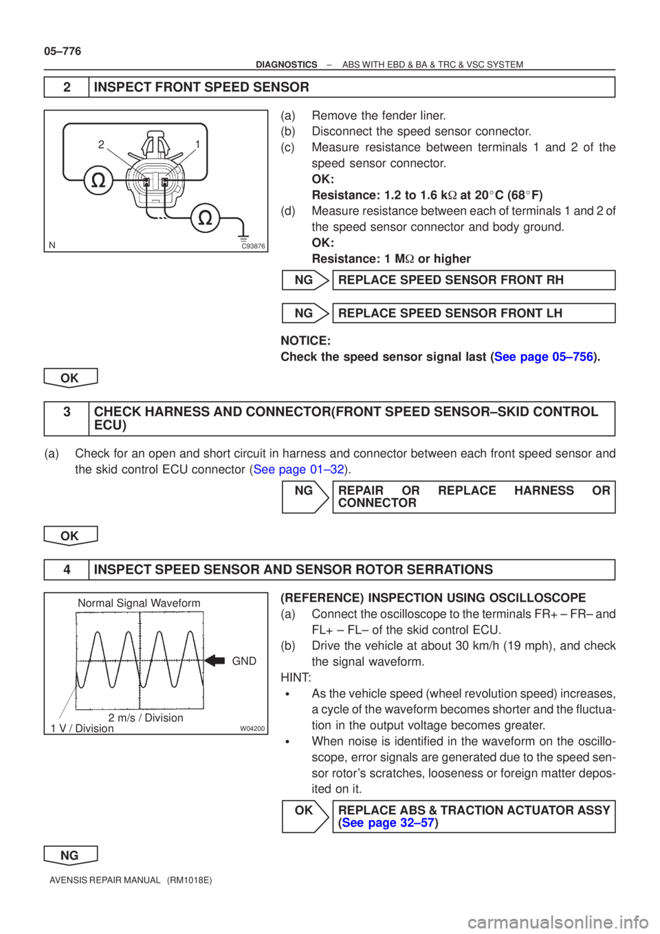
C93876
21
W04200
Normal Signal Waveform
1 V / Division 2 m/s / Division GND
05±776
±
DIAGNOSTICS ABS WITH EBD & BA & TRC & VSC SYSTEM
AVENSIS REPAIR MANUAL (RM1018E)
2INSPECT FRONT SPEED SENSOR
(a)Remove the fender liner.
(b)Disconnect the speed sensor connector.
(c)Measure resistance between terminals 1 and 2 of the speed sensor connector.
OK:
Resistance: 1.2 to 1.6 k �at 20 �C (68 �F)
(d)Measure resistance between each of terminals 1 and 2 of
the speed sensor connector and body ground.
OK:
Resistance: 1 M � or higher
NGREPLACE SPEED SENSOR FRONT RH
NGREPLACE SPEED SENSOR FRONT LH
NOTICE:
Check the speed sensor signal last (See page 05±756).
OK
3CHECK HARNESS AND CONNECTOR(FRONT SPEED SENSOR±SKID CONTROL ECU)
(a)Check for an open and short circuit in harness and connector between each fro\
nt speed sensor and
the skid control ECU connector (See page 01±32).
NGREPAIR OR REPLACE HARNESS ORCONNECTOR
OK
4INSPECT SPEED SENSOR AND SENSOR ROTOR SERRATIONS
(REFERENCE) INSPECTION USING OSCILLOSCOPE
(a)Connect the oscilloscope to the terminals FR+ ± FR± and FL+ ± FL± of the skid control ECU.
(b)Drive the vehicle at about 30 km/h (19 mph), and check
the signal waveform.
HINT:
�As the vehicle speed (wheel revolution speed) increases,
a cycle of the waveform becomes shorter and the fluctua-
tion in the output voltage becomes greater.
�When noise is identified in the waveform on the oscillo-
scope, error signals are generated due to the speed sen-
sor rotor's scratches, looseness or foreign matter depos-
ited on it.
OKREPLACE ABS & TRACTION ACTUATOR ASSY (See page 32±57)
NG
Page 891 of 5135
05±824
±
DIAGNOSTICS ABS WITH EBD & BA & TRC & VSC SYSTEM
AVENSIS REPAIR MANUAL (RM1018E)
INSPECTION PROCEDURE
1CHECK HARNESS AND CONNECTOR(YAW RATE SENSOR ± SKID CONTROL ECU)
(a)Check for an open or short circuit in harness and connector between the \
yaw rate sensor and skid
control ECU (See page 01±32).
NG REPAIR OR REPLACE HARNESS ORCONNECTOR
OK
2 CHECK HARNESS AND CONNECTOR(STEERING ANGLE SENSOR ± SKID CONTROL ECU)
(a) Check for an open or short circuit in harness and connector between the steer\
ing angle sensor and
skid control ECU (See page 01±32).
NG REPAIR OR REPLACE HARNESS ORCONNECTOR
OK
REPLACE ABS & TRACTION ACTUATOR ASSY(See page 32±57)
Page 892 of 5135

C94397
GND
IG1
±
DIAGNOSTICS ABS WITH EBD & BA & TRC & VSC SYSTEM
05±819
AVENSIS REPAIR MANUAL (RM1018E)
DTCC1300/62SKID CONTROL ECU MALFUNCTION
CIRCUIT DESCRIPTION
DTC No.DTC Detecting ConditionTrouble Area
C1300/62
1.Skid control ECU continuously detects the continuous
operation of ABS at all 4 wheels for max. 1.28 sec.
2.Continuos VSC operation for 10 sec. or more.
3.Internal malfunction in ECU.
� ECU
INSPECTION PROCEDURE
1RECONFIRM DTC
ADTC C1300/62
BExcept DTC C1300/62
BREPAIR CIRCUIT INDICATED BY OUTPUT
CODE
A
2INSPECT SKID CONTROL ECU CONNECTOR(IG1 TERMINAL VOLTAGE)
WITH USING HAND±HELD TESTER:
(a)Check the voltage condition, which is output from the ECU and displayed \
on the hand±held tester. OK:
ºNormalº is displayed.
WITHOUT USING HAND±HELD TESTER:
(a)Disconnect the skid control connector.
(b)Turn the ignition switch ON.
(c)Measure the voltage between terminals IG1 and GND ofthe skid control ECU harness side connector.
OK:
Voltage: 10 to 14 V
OKREPLACE ABS & TRACTION ACTUATOR ASSY (See page 32±57)
NG
05789±02
Page 894 of 5135
05±818
±
DIAGNOSTICS ABS WITH EBD & BA & TRC & VSC SYSTEM
AVENSIS REPAIR MANUAL (RM1018E)
DTCC1288/88ECU VERSION MISS MATCHI
CIRCUIT DESCRIPTION
DTC No.DTC Detecting ConditionTrouble Area
C1288/88
When either of the following 1 or 2 is detected:
1.ECM does not match.
2.Steering angle sensor is not calibrated.� ECM
� Steering angle sensor calibration.
INSPECTION PROCEDURE
1PERFORM STEERING ANGLE SENSOR ZERO POINT CALIBRATION
(a)Perform the steering angle sensor zero point calibration (See page 05±756).
2 RECONFIRM DTC
(a) Check if the same DTC is stored in the memory.
NO END
YES
3 CHECK HARNESS AND CONNECTOR(STEERING ANGLE SENSOR ± SKID CONTROL ECU)
(a) Check for an open or short circuit in harness and connector between the \
steering angle sensor and
skid control ECU (See page 01±32).
NG REPAIR OR REPLACE HARNESS ORCONNECTOR
OK
REPLACE ABS & TRACTION ACTUATOR ASSY(See page 32±57)
05788±02
Page 897 of 5135

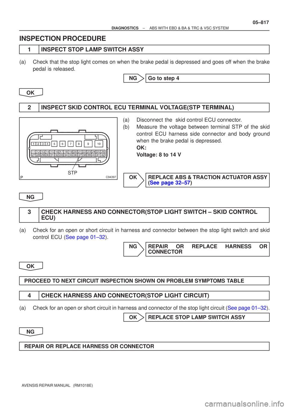
C94397STP
±
DIAGNOSTICS ABS WITH EBD & BA & TRC & VSC SYSTEM
05±817
AVENSIS REPAIR MANUAL (RM1018E)
INSPECTION PROCEDURE
1INSPECT STOP LAMP SWITCH ASSY
(a)Check that the stop light comes on when the brake pedal is depressed and goes\
off when the brake
pedal is released.
NGGo to step 4
OK
2INSPECT SKID CONTROL ECU TERMINAL VOLTAGE(STP TERMINAL)
(a)Disconnect the skid control ECU connector.
(b)Measure the voltage between terminal STP of the skid control ECU harness side connector and body ground
when the brake pedal is depressed.
OK:
Voltage: 8 to 14 V
OKREPLACE ABS & TRACTION ACTUATOR ASSY (See page 32±57)
NG
3 CHECK HARNESS AND CONNECTOR(STOP LIGHT SWITCH ± SKID CONTROL ECU)
(a) Check for an open or short circuit in harness and connector between the stop light switch and skid
control ECU (See page 01±32).
NG REPAIR OR REPLACE HARNESS ORCONNECTOR
OK
PROCEED TO NEXT CIRCUIT INSPECTION SHOWN ON PROBLEM SYMPTOMS TABLE
4 CHECK HARNESS AND CONNECTOR(STOP LIGHT CIRCUIT)
(a)Check for an open or short circuit in harness and connector of the stop light\
circuit (See page 01±32). OK REPLACE STOP LAMP SWITCH ASSY
NG
REPAIR OR REPLACE HARNESS OR CONNECTOR
Page 900 of 5135
C94397STP
05±814
±
DIAGNOSTICS ABS WITH EBD & BA & TRC & VSC SYSTEM
AVENSIS REPAIR MANUAL (RM1018E)
4INSPECT SKID CONTROL ECU TERMINAL VOLTAGE(STP TERMINAL)
(a)Disconnect the skid control ECU connector.
(b)Measure the voltage between terminal STP of the skid control ECU harness side connector and body ground
when the brake pedal is depressed.
OK:
Voltage: 8 to 14 V
NGREPAIR OR REPLACE HARNESS OR CONNECTOR
OK
REPLACE ABS & TRACTION ACTUATOR ASSY(See page 32±57)
Page 903 of 5135
F45090
Driver Side J/BECU±IG
C94397
GND
IG1
05±810
±
DIAGNOSTICS ABS WITH EBD & BA & TRC & VSC SYSTEM
AVENSIS REPAIR MANUAL (RM1018E)
INSPECTION PROCEDURE
1INSPECT FUSE(ECU±IG FUSE)
(a)Remove the ECU±IG fuse from the driver side J/B.
(b)Check continuity of the ECU±IG fuse. OK:
Continuity
NGINSPECT FOR SHORT CIRCUIT IN ALL HARNESS AND COMPONENTS CONNECTED
TO ECU±IG FUSE
OK
2INSPECT BATTERY
OK:
Voltage: 10 to 14 V NGINSPECT CHARGING SYSTEM
OK
3INSPECT SKID CONTROL ECU TERMINAL VOLTAGE(IG1 TERMINAL)
IN CASE OF USING HAND±HELD TESTER:
(a)Check the voltage condition, which is output from the ECU and displayed \
on the hand±held tester. OK:
ºNormalº is displayed. IN CASE OF NOT USING HAND±HELD TESTER:
(a)Disconnect the skid control connector.
(b)Turn the ignition switch ON.
(c)Measure the voltage between terminals IG1 and GND ofthe skid control ECU harness side connector.
OK:
Voltage: 10 to 14 V
OKREPLACE ABS & TRACTION ACTUATOR ASSY (See page 32±57)
NG