Page 2289 of 5135
A09571
Front
X Measuring Point
A80117
A
B
C
D
E
A56055
14±336
± ENGINE MECHANICALCYLINDER HEAD GASKET (1CD±FTV)
AVENSIS REPAIR MANUAL (RM1018E)
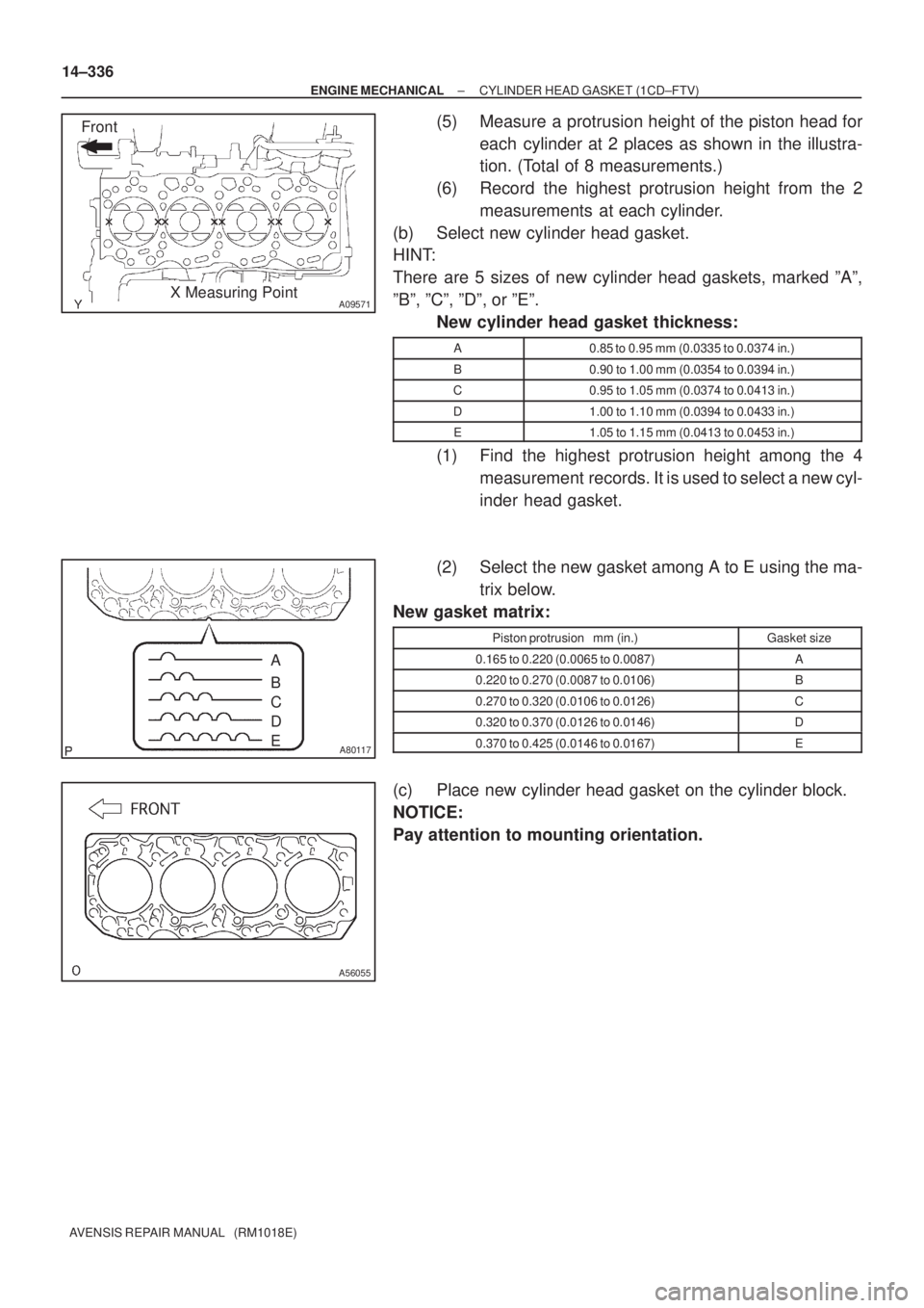
(5) Measure a protrusion height of the piston head for
each cylinder at 2 places as shown in the illustra-
tion. (Total of 8 measurements.)
(6) Record the highest protrusion height from the 2
measurements at each cylinder.
(b) Select new cylinder head gasket.
HINT:
There are 5 sizes of new cylinder head gaskets, marked ºAº,
ºBº, ºCº, ºDº, or ºEº.
New cylinder head gasket thickness:
A0.85 to 0.95 mm (0.0335 to 0.0374 in.)
B0.90 to 1.00 mm (0.0354 to 0.0394 in.)
C0.95 to 1.05 mm (0.0374 to 0.0413 in.)
D1.00 to 1.10 mm (0.0394 to 0.0433 in.)
E1.05 to 1.15 mm (0.0413 to 0.0453 in.)
(1) Find the highest protrusion height among the 4
measurement records. It is used to select a new cyl-
inder head gasket.
(2) Select the new gasket among A to E using the ma-
trix below.
New gasket matrix:
Piston protrusion mm (in.)Gasket size
0.165 to 0.220 (0.0065 to 0.0087)A
0.220 to 0.270 (0.0087 to 0.0106)B
0.270 to 0.320 (0.0106 to 0.0126)C
0.320 to 0.370 (0.0126 to 0.0146)D
0.370 to 0.425 (0.0146 to 0.0167)E
(c) Place new cylinder head gasket on the cylinder block.
NOTICE:
Pay attention to mounting orientation.
Page 2324 of 5135
A79140
A79184
14±288
±
ENGINE MECHANICAL PARTIAL ENGINE ASSY(1CD±FTV)
AVENSIS REPAIR MANUAL (RM1018E)
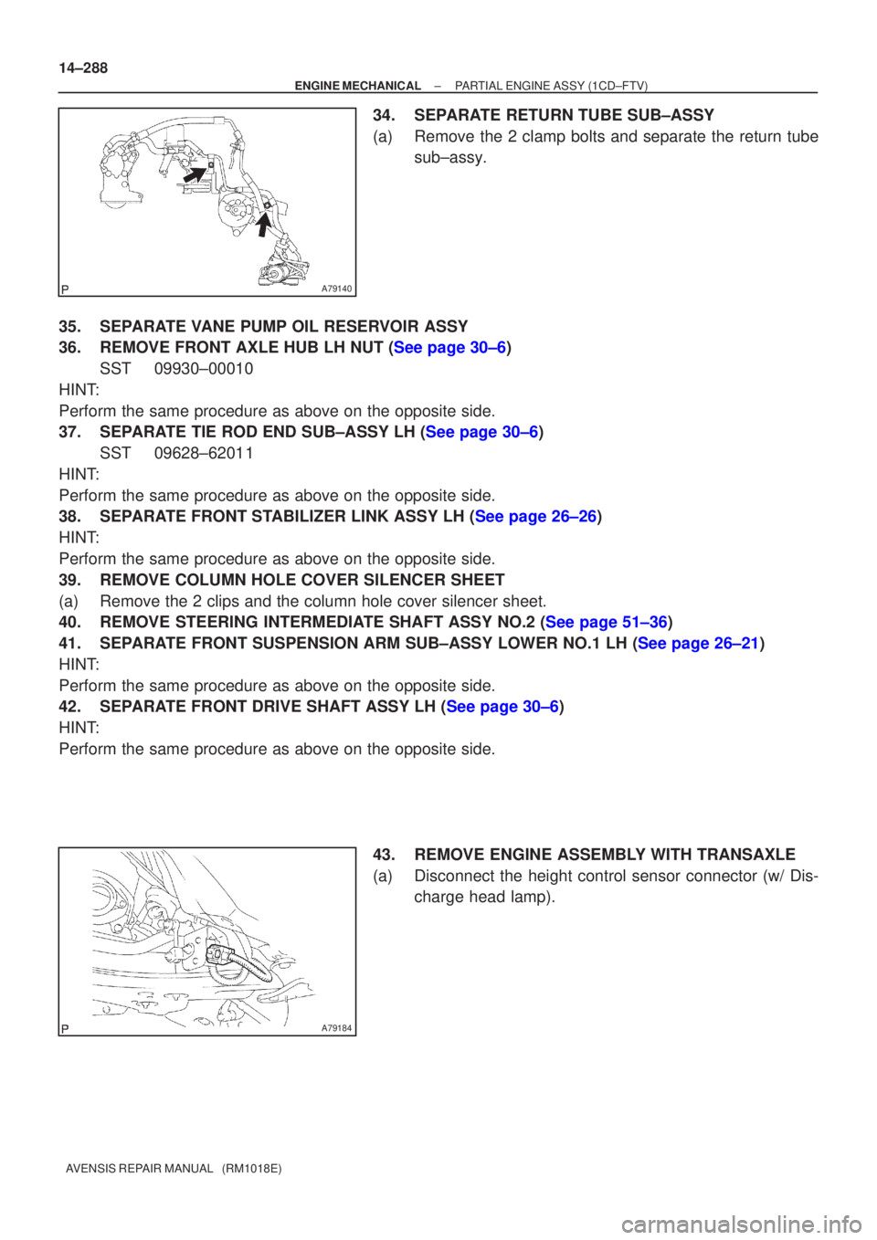
34.SEPARATE RETURN TUBE SUB±ASSY
(a)Remove the 2 clamp bolts and separate the return tube sub±assy.
35.SEPARATE VANE PUMP OIL RESERVOIR ASSY
36.REMOVE FRONT AXLE HUB LH NUT (See page 30±6) SST09930±00010
HINT:
Perform the same procedure as above on the opposite side.
37.SEPARATE TIE ROD END SUB±ASSY LH (See page 30±6) SST 09628±62011
HINT:
Perform the same procedure as above on the opposite side.
38.SEPARATE FRONT STABILIZER LINK ASSY LH (See page 26±26)
HINT:
Perform the same procedure as above on the opposite side.
39. REMOVE COLUMN HOLE COVER SILENCER SHEET
(a) Remove the 2 clips and the column hole cover silencer sheet.
40.REMOVE STEERING INTERMEDIATE SHAFT ASSY NO.2 (See page 51±36)
41.SEPARATE FRONT SUSPENSION ARM SUB±ASSY LOWER NO.1 LH (See page 26±21)
HINT:
Perform the same procedure as above on the opposite side.
42.SEPARATE FRONT DRIVE SHAFT ASSY LH (See page 30±6)
HINT:
Perform the same procedure as above on the opposite side.
43. REMOVE ENGINE ASSEMBLY WITH TRANSAXLE
(a) Disconnect the height control sensor connector (w/ Dis-charge head lamp).
Page 2462 of 5135
F45154
Rack & Pinion
Power Steering Gear Assy
Tie Rod End
Sub±assy LH
Front Stabilizer Link
Assy LH
Stabilizer Bar Front Front Stabilizer Link
Assy RH
Front Suspension Arm
Sub±assy Lower No.1 RH
Front Suspension
Member Brace
Rear RHFront Stabilizer
Bar Bush No.1
Front Suspension
Crossmember Sub±assy
Front Suspension
Arm Sub±assy
Lower No.1 LH
Body Mounting
Stopper Rear
Front Suspension
Member Body
Mounting Stopper FR
Front Suspension
Member Brace Rear LH
Cotter Pin �
89 (908, 66)
133 (1,360, 98)
49 (500, 36)
74 (755, 55)
80 (816, 59)
133 (1,360, 98)
74 (755, 55)
49 (500, 36)
80 (816, 59)
19 (194, 14)
19 (194, 14)
133 (1,360, 98)
80 (816, 59)
133 (1,360, 98)
80 (816, 59)
19 (194, 14)
49 (500, 36)
74 (755, 55)
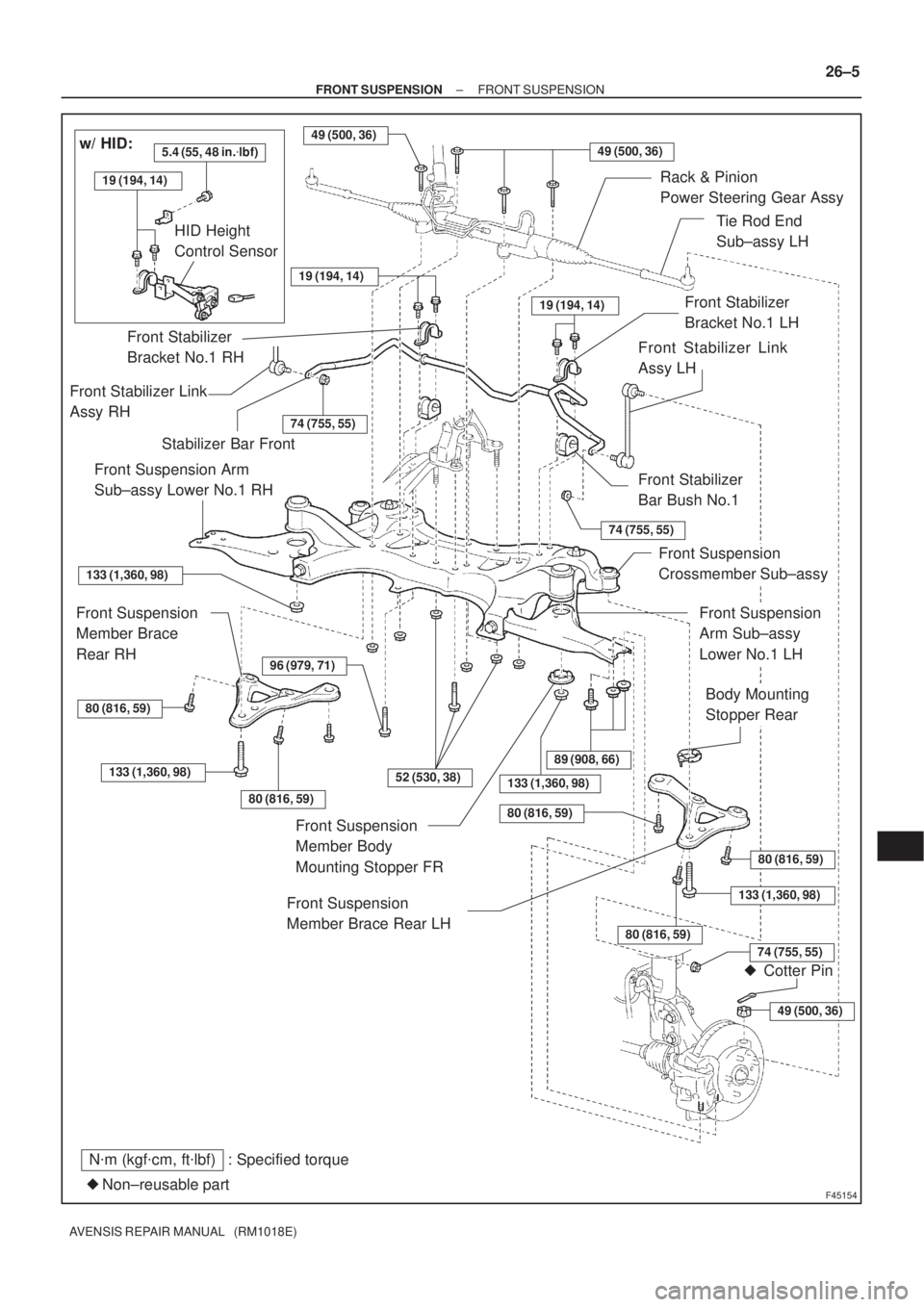
N�m (kgf�cm, ft�lbf) : Specified torque
Non±reusable part �
5.4 (55, 48 in.�lbf)w/ HID:
HID Height
Control Sensor
Front Stabilizer
Bracket No.1 RH
Front Stabilizer
Bracket No.1 LH
96 (979, 71)
80 (816, 59)
52 (530, 38)
± FRONT SUSPENSIONFRONT SUSPENSION
26±5
AVENSIS REPAIR MANUAL (RM1018E)
Page 2497 of 5135
270E1±01
SA3213
AD B
Front
C
G23862
27±4
±
REAR SUSPENSION REAR WHEEL ALIGNMENT
AVENSIS REPAIR MANUAL (RM1018E)
REAR WHEEL ALIGNMENT
ADJUSTMENT
1.INSPECT TIRE (See page 28±1)
2.MEASURE VEHICLE HEIGHT (See page 26±6)
NOTICE:
Before inspecting the wheel alignment, adjust the vehicle height to the \
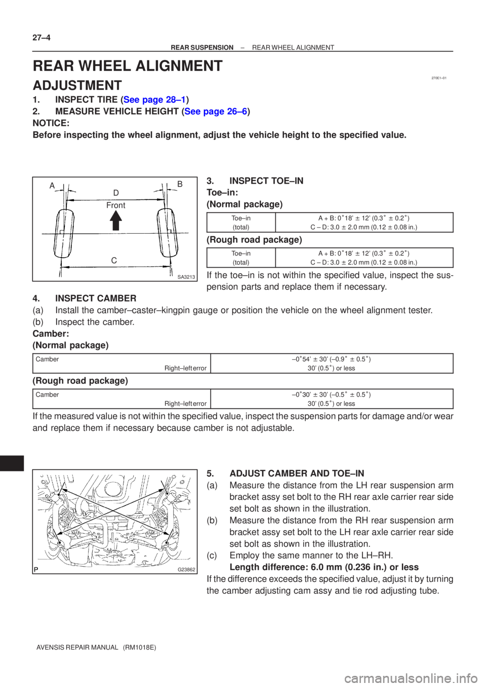
specified value. 3. INSPECT TOE±IN
Toe±in:
(Normal package)
Toe±in(total)A + B: 0 �18' \b 12' (0.3 � \b 0.2 �)
C ± D: 3.0 \b 2.0 mm (0.12 \b 0.08 in.)
(Rough road package)
Toe±in
(total)A + B: 0 ���' \b 12' (0.3 � \b 0.2 �)
C ± D: 3.0 \b 2.0 mm (0.12 \b 0.08 in.)
If the toe±in is not within the specified value, inspect the sus-
pension parts and replace them if necessary.
4. INSPECT CAMBER
(a) Install the camber±caster±kingpin gauge or position the vehicle on\
the wheel alignment tester.
(b) Inspect the camber.
Camber:
(Normal package)
Camber
Right±left error±0��� ' \b 30' (±0.9 � \b 0.5 �)
30' (0.5 �) or less
(Rough road package)
Camber
Right±left error±0��� ' \b 30' (±0.5 � \b 0.5 �)
30' (0.5 �) or less
If the measured value is not within the specified value, inspect the suspension parts for damage and/or wear
and replace them if necessary because camber is not adjustable.
5. ADJUST CAMBER AND TOE±IN
(a) Measure the distance from the LH rear suspension armbracket assy set bolt to the RH rear axle carrier rear side
set bolt as shown in the illustration.
(b) Measure the distance from the RH rear suspension arm bracket assy set bolt to the LH rear axle carrier rear side
set bolt as shown in the illustration.
(c) Employ the same manner to the LH±RH.
Length difference: 6.0 mm (0.236 in.) or less
If the difference exceeds the specified value, adjust it by turning
the camber adjusting cam assy and tie rod adjusting tube.
Page 2501 of 5135
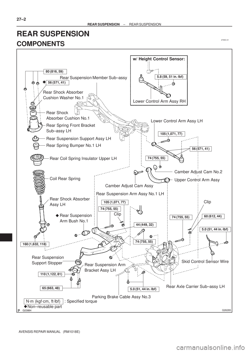
270E0±01
������G26285
w/ Height Control Sensor:
5.8 (59, 51 in.�lbf)
80 (816, 59)
Rear Suspension Member Sub±assy
Rear Shock Absorber
Cushion Washer No.1
Coil Rear Spring
Rear Coil Spring Insulator Upper LH
Rear Spring Bumper No.1 LH
Rear Suspension Support Assy LH
Rear Spring Front Bracket
Sub±assy LH
Rear Shock
Absorber Cushion No.1
Lower Control Arm Assy RH
Rear Shock Absorber
Assy LH
160 (1,632, 118)
110 (1,122, 81)
65 (663, 48)
Rear Suspension
Support Stopper
Rear Suspension Arm
Bracket Assy LH
Rear Suspension
Arm Bush No.1�Camber Adjust Cam Assy
Rear Suspension Arm Assy No.1 LH
74 (755, 55)
105 (1,071, 77)
44 (449, 32)
74 (755, 55)
74 (755, 55)
Parking Brake Cable Assy No.3
5.0 (51, 44 in.�lbf)Rear Axle Carrier Sub±assy LH
Skid Control Sensor Wire
74 (755, 55)
Upper Control Arm Assy
Camber Adjust Cam No.2
Lower Control Arm Assy LH
105 (1,071, 77)
5.0 (51, 44 in.�lbf)
60 (612, 44)
N�m (kgf�cm, ft�lbf) : Specified torque
Non±reusable part �
56 (571, 41)
�56 (571, 41)
Clip
Clip 27±2
± REAR SUSPENSIONREAR SUSPENSION
AVENSIS REPAIR MANUAL (RM1018E)
REAR SUSPENSION
COMPONENTS
Page 2505 of 5135
F45155
������F40197
Inner SideRear
Side
±
FRONT SUSPENSION STABILIZER BAR FRONT
26±27
AVENSIS REPAIR MANUAL (RM1018E)
10. SUSPEND ENGINE ASSY
(a)1ZZ, 3ZZ Engine: See page 41±15
(b)1AZ Engine: See page 41±24
(c)1CD Engine: See page 41±33
11.REMOVE FRONT SUSPENSION MEMBER BRACE REAR LH (See page 26±16)
12. REMOVE FRONT SUSPENSION MEMBER BRACE REAR RH
HINT:
Remove the RH side by the same procedures as the LH side.
13.SEPARATE FRONT SUSPENSION CROSSMEMBER SUB±ASSY (See page 26±16)
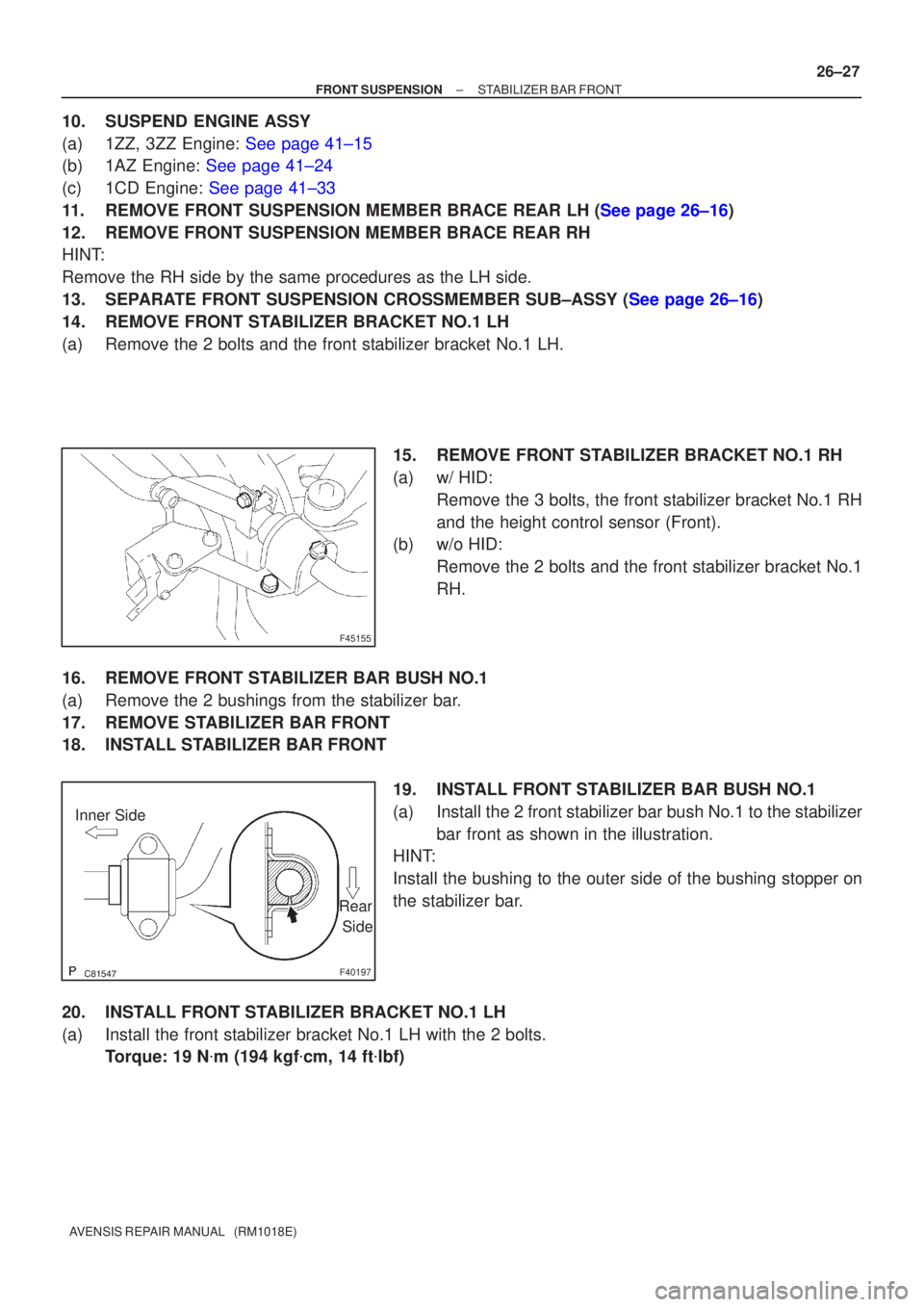
14. REMOVE FRONT STABILIZER BRACKET NO.1 LH
(a) Remove the 2 bolts and the front stabilizer bracket No.1 LH.
15. REMOVE FRONT STABILIZER BRACKET NO.1 RH
(a) w/ HID:Remove the 3 bolts, the front stabilizer bracket No.1 RH
and the height control sensor (Front).
(b) w/o HID:
Remove the 2 bolts and the front stabilizer bracket No.1
RH.
16. REMOVE FRONT STABILIZER BAR BUSH NO.1
(a) Remove the 2 bushings from the stabilizer bar.
17. REMOVE STABILIZER BAR FRONT
18. INSTALL STABILIZER BAR FRONT 19. INSTALL FRONT STABILIZER BAR BUSH NO.1
(a) Install the 2 front stabilizer bar bush No.1 to the stabilizerbar front as shown in the illustration.
HINT:
Install the bushing to the outer side of the bushing stopper on
the stabilizer bar.
20. INSTALL FRONT STABILIZER BRACKET NO.1 LH
(a) Install the front stabilizer bracket No.1 LH with the 2 bolts. Torque: 19 N �m (194 kgf �cm, 14 ft �lbf)
Page 2506 of 5135
F45155
A
B
F44620
26±28
±
FRONT SUSPENSION STABILIZER BAR FRONT
AVENSIS REPAIR MANUAL (RM1018E)
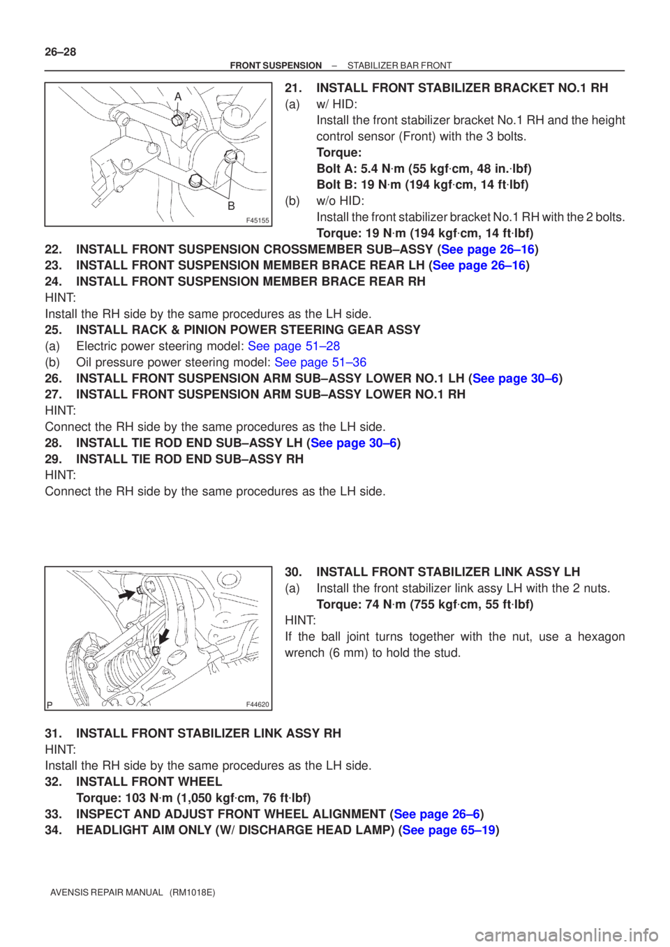
21. INSTALL FRONT STABILIZER BRACKET NO.1 RH
(a) w/ HID: Install the front stabilizer bracket No.1 RH and the height
control sensor (Front) with the 3 bolts.
Torque:
Bolt A: 5.4 N �m (55 kgf �cm, 48 in. �lbf)
Bolt B: 19 N �m (194 kgf �cm, 14 ft �lbf)
(b) w/o HID: Install the front stabilizer bracket No.1 RH with the 2 bolts.
Torque: 19 N �m (194 kgf �cm, 14 ft �lbf)
22.INSTALL FRONT SUSPENSION CROSSMEMBER SUB±ASSY (See page 26±16)
23.INSTALL FRONT SUSPENSION MEMBER BRACE REAR LH (See page 26±16)
24. INSTALL FRONT SUSPENSION MEMBER BRACE REAR RH
HINT:
Install the RH side by the same procedures as the LH side.
25. INSTALL RACK & PINION POWER STEERING GEAR ASSY
(a)Electric power steering model: See page 51±28
(b)Oil pressure power steering model: See page 51±36
26.INSTALL FRONT SUSPENSION ARM SUB±ASSY LOWER NO.1 LH (See page 30±6)
27. INSTALL FRONT SUSPENSION ARM SUB±ASSY LOWER NO.1 RH
HINT:
Connect the RH side by the same procedures as the LH side.
28.INSTALL TIE ROD END SUB±ASSY LH (See page 30±6)
29. INSTALL TIE ROD END SUB±ASSY RH
HINT:
Connect the RH side by the same procedures as the LH side.
30. INSTALL FRONT STABILIZER LINK ASSY LH
(a) Install the front stabilizer link assy LH with the 2 nuts.Torque: 74 N �m (755 kgf �cm, 55 ft �lbf)
HINT:
If the ball joint turns together with the nut, use a hexagon
wrench (6 mm) to hold the stud.
31. INSTALL FRONT STABILIZER LINK ASSY RH
HINT:
Install the RH side by the same procedures as the LH side.
32. INSTALL FRONT WHEEL Torque: 103 N �m (1,050 kgf �cm, 76 ft �lbf)
33.INSPECT AND ADJUST FRONT WHEEL ALIGNMENT (See page 26±6)
34.HEADLIGHT AIM ONLY (W/ DISCHARGE HEAD LAMP) (See page 65±19)
Page 2513 of 5135
C95317
C86742
C87504
C95318
± FRONT SUSPENSIONFRONT SUSPENSION ARM SUB±ASSY LOWER NO.1
LH (ATM)26±17
AVENSIS REPAIR MANUAL (RM1018E)
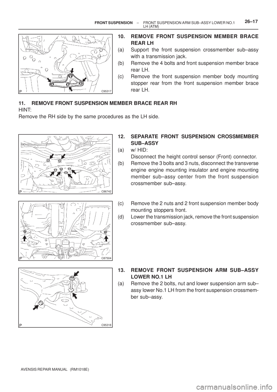
10. REMOVE FRONT SUSPENSION MEMBER BRACE
REAR LH
(a) Support the front suspension crossmember sub±assy
with a transmission jack.
(b) Remove the 4 bolts and front suspension member brace
rear LH.
(c) Remove the front suspension member body mounting
stopper rear from the front suspension member brace
rear LH.
11. REMOVE FRONT SUSPENSION MEMBER BRACE REAR RH
HINT:
Remove the RH side by the same procedures as the LH side.
12. SEPARATE FRONT SUSPENSION CROSSMEMBER
SUB±ASSY
(a) w/ HID:
Disconnect the height control sensor (Front) connector.
(b) Remove the 3 bolts and 3 nuts, disconnect the transverse
engine engine mounting insulator and engine mounting
member sub±assy center from the front suspension
crossmember sub±assy.
(c) Remove the 2 nuts and 2 front suspension member body
mounting stoppers front.
(d) Lower the transmission jack, remove the front suspension
crossmember sub±assy.
13. REMOVE FRONT SUSPENSION ARM SUB±ASSY
LOWER NO.1 LH
(a) Remove the 2 bolts, nut and lower suspension arm sub±
assy lower No.1 LH from the front suspension crossmem-
ber sub±assy.