Page 180 of 5135

A79052
A6
Mass Air Flow MeterECM
1
3 EVG
VG
L±Y
G
2
B±R 12
EA1 32
E12
24
E12
B±R
From
Terminal 2 of
EFI No.1 Fuse
(See Page 05±124)
±
DIAGNOSTICS SFI SYSTEM(1ZZ±FE/3ZZ±FE)
05±25
AVENSIS REPAIR MANUAL (RM1018E)
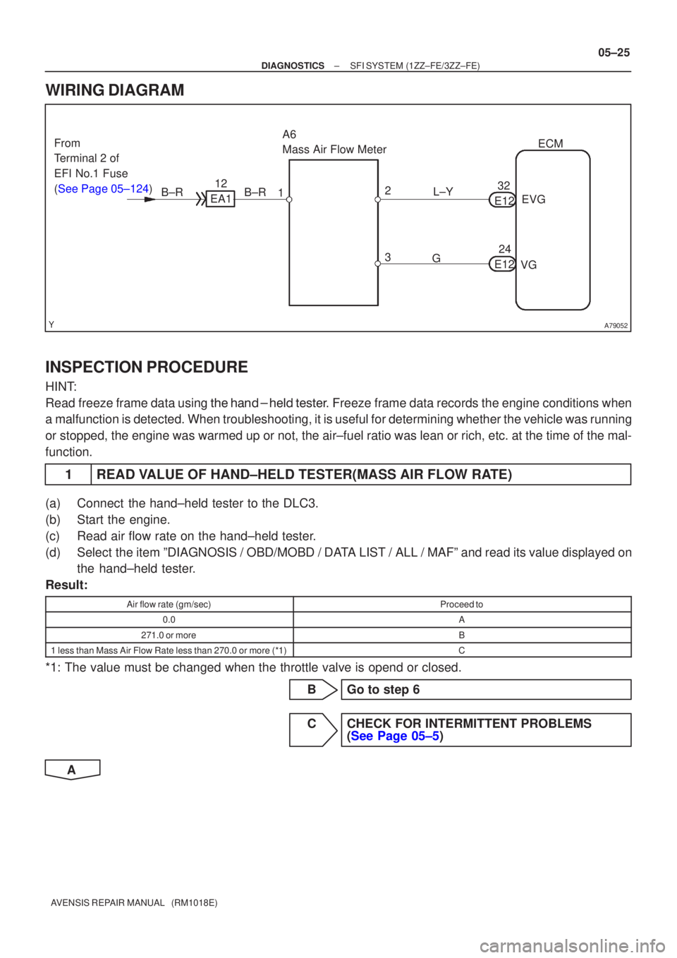
WIRING DIAGRAM
INSPECTION PROCEDURE
HINT:
Read freeze frame data using \f���� ����\b�\f��\f�
� Freeze frame data records the engine conditions when
a malfunction is detected. When troubleshooting, it is useful for determi\
ning whether the vehicle was running
or stopped, the engine was warmed up or not, the air±fuel ratio was lea\
n or rich, etc. at the time of the mal-
function.
1READ VALUE OF HAND±HELD TESTER(MASS AIR FLOW RATE)
(a)Connect the hand±held tester to the DLC3.
(b)Start the engine.
(c)Read air flow rate on the hand±held tester.
(d)Select the item ºDIAGNOSIS / OBD/MOBD / DATA LIST / ALL / MAFº and read its value displayed on the hand±held tester.
Result:
Air flow rate (gm/sec)Proceed to
0.0A
271.0 or moreB
1 less than Mass Air Flow Rate less than 270.0 or more (*1)C
*1: The value must be changed when the throttle valve is opend or closed.
BGo to step 6
CCHECK FOR INTERMITTENT PROBLEMS(See Page 05±5)
A
Page 215 of 5135

±
DIAGNOSTICS SFI SYSTEM(1ZZ±FE/3ZZ±FE)
05±65
AVENSIS REPAIR MANUAL (RM1018E)
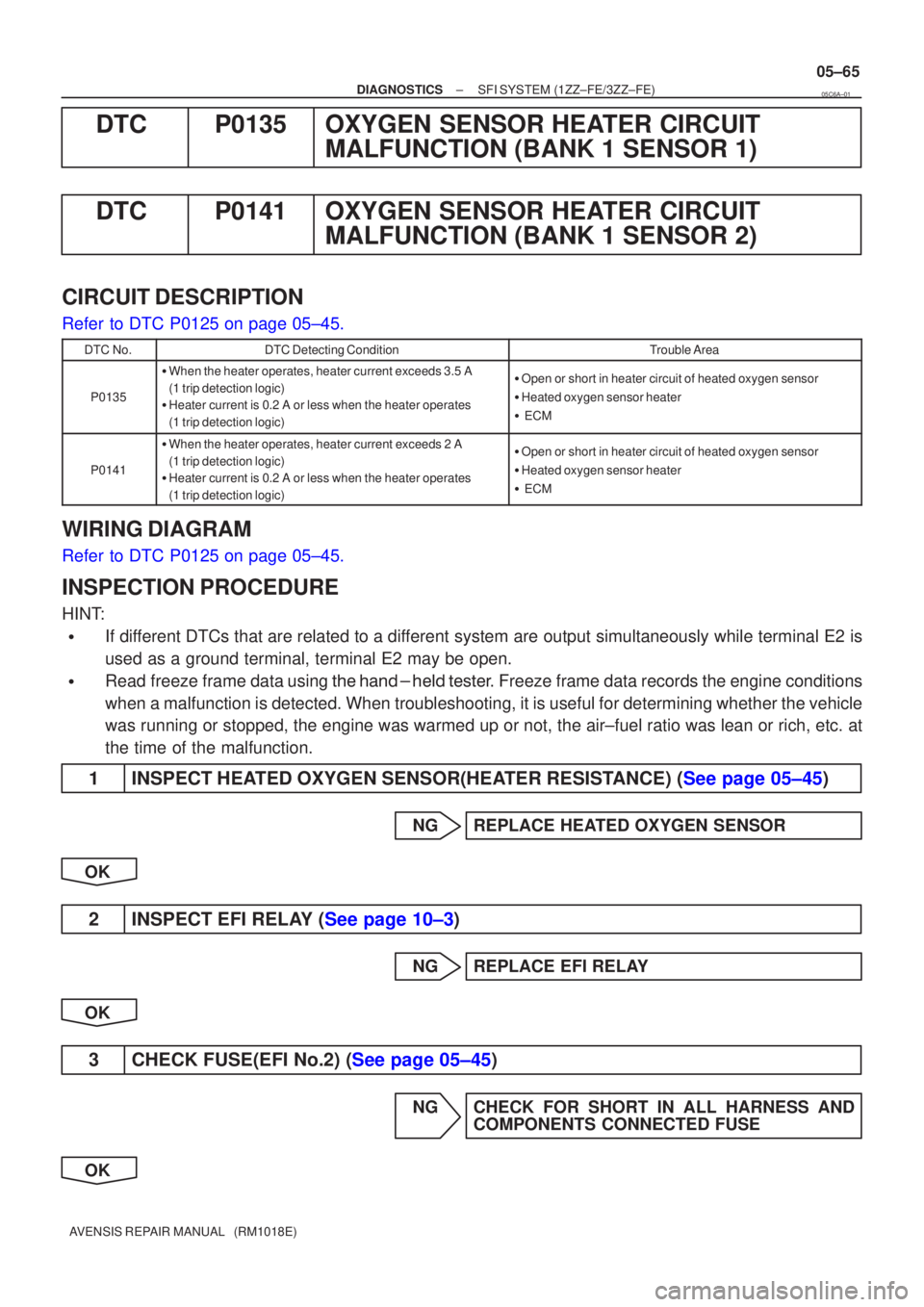
DTCP0135OXYGEN SENSOR HEATER CIRCUIT
MALFUNCTION (BANK 1 SENSOR 1)
DTCP0141OXYGEN SENSOR HEATER CIRCUIT MALFUNCTION (BANK 1 SENSOR 2)
CIRCUIT DESCRIPTION
Refer to DTC P0125 on page 05±45.
DTC No.DTC Detecting ConditionTrouble Area
P0135
�When the heater operates, heater current exceeds 3.5 A
(1 trip detection logic)
� Heater current is 0.2 A or less when the heater operates
(1 trip detection logic)�Open or short in heater circuit of heated oxygen sensor
� Heated oxygen sensor heater
� ECM
P0141
�When the heater operates, heater current exceeds 2 A
(1 trip detection logic)
� Heater current is 0.2 A or less when the heater operates
(1 trip detection logic)�Open or short in heater circuit of heated oxygen sensor
� Heated oxygen sensor heater
� ECM
WIRING DIAGRAM
Refer to DTC P0125 on page 05±45.
INSPECTION PROCEDURE
HINT:
�If different DTCs that are related to a different system are output simultaneously while terminal E2 is
used as a ground terminal, terminal E2 may be open.
�Read freeze frame data using \f���� ����\b�\f��\f�
� Freeze frame data records the engine conditions
when a malfunction is detected. When troubleshooting, it is useful for d\
etermining whether the vehicle
was running or stopped, the engine was warmed up or not, the air±fuel ra\
tio was lean or rich, etc. at
the time of the malfunction.
1INSPECT HEATED OXYGEN SENSOR(HEATER RESISTANCE) (See page 05±45)
NG REPLACE HEATED OXYGEN SENSOR
OK
2INSPECT EFI RELAY (See page 10±3)
NG REPLACE EFI RELAY
OK
3CHECK FUSE(EFI No.2) (See page 05±45)
NG CHECK FOR SHORT IN ALL HARNESS AND COMPONENTS CONNECTED FUSE
OK
05C6A±01
Page 269 of 5135

A58697
Intake Air
Chamber
Throttle Valve
To Cylinder
ISC Valve
Valve
ECM
Signal From
Air
Cleaner
From
Terminal 2 of
EFI No.1 Fuse
(See Page 05±124)
A79101
2 VISC DUTY1
GND 3
I10
ISC Valve
G±R5
E13 RSDECM
B±R 12
EA1 B±R
W±B7
E13 E01
W±B
EG
05±100
±
DIAGNOSTICS SFI SYSTEM (1ZZ±FE/3ZZ±FE)
AVENSIS REPAIR MANUAL (RM1018E)
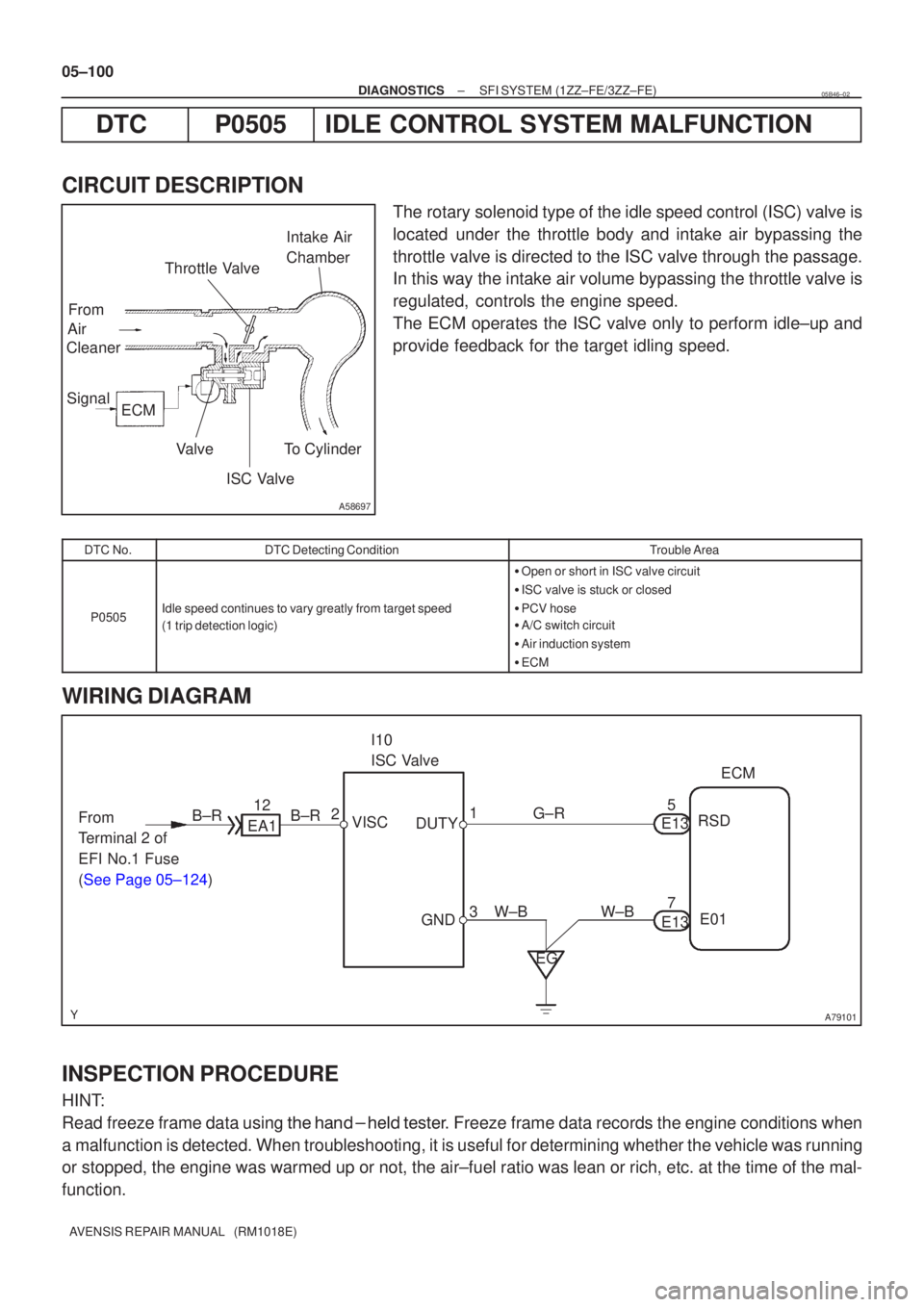
DTC P0505 IDLE CONTROL SYSTEM MALFUNCTION
CIRCUIT DESCRIPTION
The rotary solenoid type of the idle speed control (ISC) valve is
located under the throttle body and intake air bypassing the
throttle valve is directed to the ISC valve through the passage.
In this way the intake air volume bypassing the throttle valve is
regulated, controls the engine speed.
The ECM operates the ISC valve only to perform idle±up and
provide feedback for the target idling speed.
DTC No.DTC Detecting ConditionTrouble Area
P0505Idle speed continues to vary greatly from target speed
(1 trip detection logic)
� Open or short in ISC valve circuit
� ISC valve is stuck or closed
� PCV hose
� A/C switch circuit
� Air induction system
� ECM
WIRING DIAGRAM
INSPECTION PROCEDURE
HINT:
Read freeze frame data using \f�� �� ����\b� \f��\f�
� Freeze frame data records the engine conditions when
a malfunction is detected. When troubleshooting, it is useful for determi\
ning whether the vehicle was running
or stopped, the engine was warmed up or not, the air±fuel ratio was lea\
n or rich, etc. at the time of the mal-
function.
05B46±02
Page 310 of 5135
A79100
I13
Ignition Switch
45
B±RB±Y
6
1
ST
2
6Fuse
Block
B±W
B±R B±R
1
1
IP1 IE4
(*1)
(*2)
B±R
1
2
1
1A 1AM2Engine
Room
R/B No.1
and
Engine
Room
J/B No.1
B±GB±Y
55
ST
Relay 51
32
55J13J12 BB
CA9
6N1
Neutral
Start
SwitchB±Y
(*4)
ECM
STA B±Y9
E12 B±W
(*3)
B±Y
(*3)
A J13 J12
J12
Junction
Connector
Engine
Room
J/B No.4 4A 1
1
4B
B±G
FL MAIN
BatteryB±R
IJDriver
Side R/B
BW±B
Driver
Side J/B DJ 2
DA 9
W±B B
S4
S511
Stater IK1
7*1: LHD
*2: RHD
*3: A/T
*4: M/T 05±136
± DIAGNOSTICSSFI SYSTEM (1ZZ±FE/3ZZ±FE)
AVENSIS REPAIR MANUAL (RM1018E)
WIRING DIAGRAM
Page 324 of 5135

���\b�A79115
Reference (Bank 1 Sensor 2 System Drawing)Heated Oxygen Sensor
EFI Relay
Heater
SensorOX1B HT1BECM
From
Battery EFI Fuse
O1B±
MREL
EFI No.2 Fuse
05±218
±
DIAGNOSTICS SFI SYSTEM(1AZ±FE)
AVENSIS REPAIR MANUAL (RM1018E)
DTCP0141/27OXYGEN SENSOR HEATER CIRCUIT MALFUNCTION (BANK 1 SENSOR 2)
DTCP0161/29OXYGEN SENSOR HEATER CIRCUIT (BANK 2 SENSOR 2)
CIRCUIT DESCRIPTION
Refer to DTC P0136/27 on page 05±211.
HINT:
The ECM provides a pulse width modulated control circuit to adjust current \
through the heater. The heated
oxygen sensor heater circuit uses a relay on the B+ side of the circuit.
DTC No.DTC Detection ConditionTrouble Area
P0141/27
Heated current is 0.2 A or less when heater operates
(1 trip detection logic)�Open or short in heater circuit of heated oxygen sensor
� Heated oxygen sensor heater
P0141/27
P0161/29When heater operates, heated current exceeds 2 A
(1 trip detection logic)
yg
�EFI relay
� ECM
HINT:
�Bank 1 refers to the bank that includes cylinder No.1.
�Bank 2 refers to the bank that does not include cylinder No.1.
�Sensor 1 refers to the sensor closest to the engine assembly.
�Sensor 2 refers to the sensor farthest away from the engine assembly.
WIRING DIAGRAM
Refer to DTC P0136/27 on page 05±211.
INSPECTION PROCEDURE
HINT:
�If different DTCs that are related to a different system are output simultaneously while terminal E2 is
used as a ground terminal, terminal E2 may be open.
�Read freeze frame data using �
\f
���
\f�� �\f��\f�� Freeze frame data records the engine conditions
when a malfunction is detected. When troubleshooting, it is useful for d\
etermining whether the vehicle
was running or stopped, the engine was warmed up or not, the air±fuel ra\
tio was lean or rich, etc. at
the time of the malfunction.
05C6Y±01
Page 378 of 5135
A76869
Engine Room R/B No.1
Engine Room J/B No.1
EFI
12
1 1A1
B±G
4A
4B 11
Engine
Room J/B No.4
B±G
FL MAIN
Battery
EFBR B±Y
IE3
IO1 77
(LHD)(RHD)B±Y3
E9 BATTECM
E1 7
E12
A66054
Engine Room R/B No.1
EFI Fuse
05±262
± DIAGNOSTICSSFI SYSTEM (1AZ±FE)
AVENSIS REPAIR MANUAL (RM1018E)
ECM BACK±UP POWER SOURCE CIRCUIT
CIRCUIT DESCRIPTION
While the ignition switch is OFF, the battery positive voltage is supplied to terminal BATT of the ECM for the
DTCs memory and air±fuel ratio adaptive control value memory, etc.
WIRING DIAGRAM
INSPECTION PROCEDURE
1 CHECK FUSE(EFI FUSE)
(a) Remove the EFI fuse from the engine room R/B No.1.
(b) Check for continuity in the EFI fuse.
Standard: Continuity
NG CHECK FOR SHORT IN ALL HARNESSES AND
COMPONENTS CONNECTED FUSE
OK
05C78±01
Page 395 of 5135

A58697
Intake Air
Chamber
Throttle Valve
To Cylinder
ISC Valve
Valve
ECM
Signal From
Air
Cleaner
From
Terminal 2 of
EFI No.1 Fuse
(See Page 05±257)
A79101
2 +B DUTY1
GND 3
I10
ISC Valve
G±R10
E12 RSDECM
B±R 12
EA1 B±R
W±B7
E12 E1
BR
EF
±
DIAGNOSTICS SFI SYSTEM (1AZ±FE)
05±243
AVENSIS REPAIR MANUAL (RM1018E)
DTC P0511/33 IDLE AIR CONTROL CIRCUIT
CIRCUIT DESCRIPTION
The rotary solenoid type idle speed control (ISC) valve is lo-
cated under the throttle body and intake air bypassing the
throttle valve is directed to the idle speed control (ISC) valve
through the passage.
In this way the intake air volume bypassing the throttle valve is
regulated, controls the engine speed.
The ECM operates the idle speed control (ISC) valve only to
perform idle±up and provide feedback for the target idling
speed.
DTC No.DTC Detecting ConditionTrouble Area
P0511/33Idle speed continues to vary greatly from target speed
(1 trip detection logic)
�Open or short in idle speed control (ISC) valve circuit
� Idle speed control (ISC) valve is stuck or closed
� A/C switch circuit
� Air induction system
� ECM
WIRING DIAGRAM
INSPECTION PROCEDURE
HINT:
Read freeze frame data using \f�� �� ����\b� \f��\f�
� Freeze frame data records the engine conditions when
a malfunction is detected. When troubleshooting, it is useful for determi\
ning whether the vehicle was running
or stopped, the engine was warmed up or not, the air±fuel ratio was lea\
n or rich, etc. at the time of the mal-
function.
05C74±01
Page 453 of 5135
A76870
ECM
STA
E129
B±Y
IJW±BJ12
B B J13
J/C W±B 1 5
32 1AM2 2
B±G
B±R1
S51S4
Starter
Battery7
IK1
FL MAIN 4B 4A
Engine Room
J/B No. 4
BB 55
55 1
11A
B±GB±R
IE41
(LHD)IP11
(RHD)B±R
Engine
Room
R/B No. 1
Engine
Room
J/B No.1
Driver
Side R/BST
Relay
2DJ
9DA Driver
Side J/B B±R
B±RI13
Ignition Switch
45B±Y
B±Y
6
2ST 1
6 Fuse
Block
B±WB±YB±Y B±Y
J12 A C J13
A
J12 1
1
(M/T)
B±W
(A/T)
N1
Neutral Start SW96B±Y
(A/T) 05±278
± DIAGNOSTICSSFI SYSTEM (1AZ±FE)
AVENSIS REPAIR MANUAL (RM1018E)
STARTER SIGNAL CIRCUIT
CIRCUIT DESCRIPTION
When the engine is cranked, the intake air flow becomes slow, so fuel vaporization is poor. A rich mixture
is therefore necessary in order to achieve good startability. While the engine is being cranked, the battery
voltage is applied to terminal STA of the ECM. The starter signal is mainly used to increase the fuel injection
volume for the starting injection control and after±start injection control.
WIRING DIAGRAM
05C7B±01