Page 4155 of 5135

A76877
ECM
+BM
FL MAINTHROTTLE Engine Room J/B No.1
Engine Room R/B No.1
E10
IE2 1A 4B15
2 Engine Room J/B No. 4
6
B−G
Battery4A1
B−G
1 1
1G−RG−Y
A82233
THROTTLE Fuse Engine Room R/B No.1:
A67446
+BM (+) E1(−)
E10E11
ECM Connector
05−220
− DIAGNOSTICSSFI SYSTEM (2AZ−FSE)
AVENSIS Supplement (RM1045E)
WIRING DIAGRAM
INSPECTION PROCEDURE
HINT:
Read freeze frame data usingthe hand−held tester. Freeze frame data records the engine conditions when
a malfunction is detected. When troubleshooting, freeze frame data can help determine if the vehicle was
running or stopped, if the engine was warmed up or not, if the air−fuel ratio was lean or rich, and other data
from the time the malfunction occurred.
1CHECK FUSE(THROTTLE FUSE)
(a) Remove the THROTTLE fuse from the engine room R/B
No.1.
(b) Check for continuity in the THROTTLE fuse.
Standard: Continuity
(c) Reinstall the THROTTLE fuse.
NG CHECK FOR SHORT IN ALL HARNESSES AND
COMPONENTS CONNECTED TO FUSE
OK
2 INSPECT ECM(+BM VOLTAGE)
(a) Measure the voltage between the specified terminals of
the E10 and E11ECM connectors.
Standard:
Tester ConnectionSpecified Condition
+BM (E10−6)−E1(E11−1)9to14V
Page 4169 of 5135

A76870
I13
Ignition SW
B−R
StarterECM
FL MAIN
BatterySTA E1317 B−Y
B−Y
B−W
W−B 1
2 35
9
W−B 1
1
B−R B−G 1
1B−G
4A 1A 2
DA Engine
Room
R/B No. 4Driver
Side J/B
S4
S5 14B1AM2Engine
Room
R/B No. 1 1IE41
(LHD)IP11
(RHD)B−RB−R
B−R
55
55
2DJ
IJ IK1 7B
BST
RelayDriver
Side
R/B5
4
AM2 ST2
B−Y
B−Y
A J12 B J12C J13 B J13
A J12
B−Y
(M/T) 6
6 1
2STFuse
Block
J/C
B−Y
(A/T) B−W
(A/T)
96
N1
Park/Neutral Position SwitchB−Y
− DIAGNOSTICSSFI SYSTEM (2AZ−FSE)
05−203
AVENSIS Supplement (RM1045E)
DTC P0617 STARTER RELAY CIRCUIT HIGH
CIRCUIT DESCRIPTION
While the engine is being cranked, the positive battery voltage is applied to terminal STA of the ECM.
If the vehicle is being driven and the ECM detects the starter control signal (STA), the ECM concludes that
the starter control circuit is malfunctioning. The ECM will turn on the CHK ENG and a DTC is set.
DTC No.DTC Detection ConditionTrouble Area
P0617
When all conditions (a), (b) and (c) are satisfied with battery
(+B) voltage 10.5 V or more for 20 seconds:
(a) Vehicle speed greater than 12 mph (20 km/h)
(b) Engine speed greater than 1,000 rpm
(c) STA signal ONSShort in Park/Neutral position switch (A/T)
SPark/Neutral position switch (A/T)
SIgnition switch
SECM
WIRING DIAGRAM
05HIO−01
Page 4293 of 5135
A91217
MREL
W
GRE9
IE5
B
Battery FL MAINAF2+ 8
1 126
Engine Room
R/B No. 1ECM
6AGR
3AF2−
HAF2
E1 E1035
E1034 1
IP1 (RHD)(LHD) 1
2
W
1
2
1
11B
W
2
1
325
3
W−B
A
A
A
W−B(RHD)
(LHD)W−B
A
IP IKEI J17
J/C
J15
J/C B−R
Fuse Block
A/F AM1 No. 1 140A ALT
A35
A/F Sensor
Relay B−R
W
(*1)W
(*2)
IH2 1
B−W
(*1)A34A34 A34 A34A34
A34
A34
A34 2
2 11 3
44
3
+B AF+
AF−
HT B
(*1)
(*2)
(*1)
(*2) (*2)
B(*1)
(*3)W(*1)
W
(*2) IH2 3
IH2 4
B
(*1)BR
(*1)
A34
A/F sensor BR
E12
E127 5
IK1 3
L−RL−R
(*2)
L−R
(*1) IH2
2R
(*1)
BR J/C J13
J12 D
E
BR
*1: w/ Headlight Beam Level Control
*2: w/o Headlight Beam Level Control
*3: Shielded
− DIAGNOSTICSECD SYSTEM (1CD−FTV)(From September, 2003)
05−307
AVENSIS Supplement (RM1045E)
WIRING DIAGRAM
Page 4369 of 5135
A81016
ECM
STA
E97
B−Y
IJW−BJ12
B B
J13
J/C W−B 1 5
32 1AM2 2
B
B−R1
S51
S4
Starter
Battery7IK1
FL MAIN 3 3
Engine Room
R/B No. 3
B B 55
55 1
11A
BB−R
IE41
(LHD)IP11
(RHD)B−R
Engine
Room
R/B No. 1
Driver
Side R/B ST
Relay
2
DJ
9
DADriver
Side J/B B−R
B−RI13
Ignition Switch
4
5
AM2 ST2B−Y
B−Y
6
2ST 1
6 Fuse
Block
B−WB−YB−Y B−Y
J12
A C
J13C
J13 05−494
− DIAGNOSTICSECD SYSTEM (1CD−FTV)(From September, 2003)
AVENSIS Supplement (RM1045E)
STARTER SIGNAL CIRCUIT
CIRCUIT DESCRIPTION
HINT:
While the engine is being cranked, current flows from terminal ST2 of the ignition switch to the ST relay coil
and also current flows to terminal STA of the ECM (STA signal).
WIRING DIAGRAM
05I7V−01
Page 4460 of 5135

A81506
From Battery
Glow System Wiring Diagram:
Glow Plug Relay
Glow Plug ECM
GREL
GLOW Fuse
−
DIAGNOSTICS ECD SYSTEM (1CD−FTV)(From September, 2003)
05 −389
AVENSIS Supplement (RM1045E)
INSPECTION PROCEDURE
HINT:
S After completing repairs, confirm that P0380 is not present again.
S Read freeze frame data using the hand −held tester. Freeze frame data records the engine conditions
when a malfunction is detected. When troubleshooting, freeze frame data can help determine if the
vehicle was running or stopped, if the engine was warmed up or not, if the air −fuel ratio was lean or
rich, and other data from the time the malfunction occurred.
1 CHECK OTHER DTC OUTPUT(IN ADDITION TO DTC P0380)
(a) Connect the hand −held tester to the DLC3.
(b) Turn the ignition switch to ON and turn the hand −held tester ON.
(c) Select the item ”DIAGNOSIS / OBD/MOBD / DTC INFO / CURRENT CODES”.
(d) Read DTCs.
Result:
Display (DTC output)Proceed to
P0380A
P0380 and P0622B
HINT:
If any other codes besides P0380 and P0622 are output, perform troubleshooting for those DTCs first.
B GO TO RELEVANT DTC CHART(See page 05 −299)
A
Page 4527 of 5135
G30839
E9
N
D 6ECM
E10
E9
E10
E13
E10
E10
E10P
R
STA
SPT1
SFTD
SFTU W−L
J5 J/C
R−Y
CC
J/C
J23C A IK220
5
R W−L
R−Y 1 PL
RL
NL
DL
6 75 RBIK1
IK1 1
R−W
J/C
J13J12 BB
B−W
Fuse Block
66
21 ST
B−Y
Center J/B
CG
CDCA
CA87
1 1
I13 Ignition SW
AM2 ST2
AM1IG1 4
3
1G−Y
G−R
B−RDHDHDN DA DB
DA
AM12 13 5IG1Relay GAUGE2 GAUGE1
1 277
5
1Driver Side J/B
11
IE4IP1 3
IG S
SFTD
SFTU
E52 R−WT7 Transmission Control SW
L
B
R
J17
J/CA
A
B−R
11A
Engine Room J/B No.4AM2
2
1
B−G
W−B
J15 J/C
W−B
IP A IK IJ
4B 4A1
1 1 2ALT
1
4D
Battery
B−G
FL MAIN
*1: LHD *2: RHD(*1) R−Y(*1)
J22 2
R
LG−B
B−Y
A IK2
IK2 R−W
9
10
LG−B
B−Y
A J12 J/C
B−W
9
7
1
W−B
(*1) (*2)
1
W−B
(*1)
(*2) B−G
911
7
10
17
20
21
22
Engine Room R/B and J/B No.1
R−Y
(*2)R−Y
(*2) N1
Neutral Start SW
3
R−W
R−W
− DIAGNOSTICSELECTRONIC CONTROLLED AUTOMATIC
TRANSAXLE [ECT] (U151E)05−567
AVENSIS Supplement (RM1045E)
WIRING DIAGRAM
Page 4919 of 5135

A79114
Wire Harness Side:
Sensor 1H7
Heated Oxygen Sensor Connector
HT
OX
E1
Front View
A65746
HT1A
ECM Connector E12
OX1AE2 E13
A78602
Reference (Sensor 1 System Diagram):
Heated Oxygen Sensor
EFI Relay
Heater
Sensor
OX1A HT1AECM
From
Battery
EFI Fuse
E2
MREL OX HT
E1 +B
05–114
– DIAGNOSTICSSFI SYSTEM (1ZZ–FE/3ZZ–FE)(From February, 2004)
AVENSIS REPAIR MANUAL SUPPLEMENT
(RM1098E)
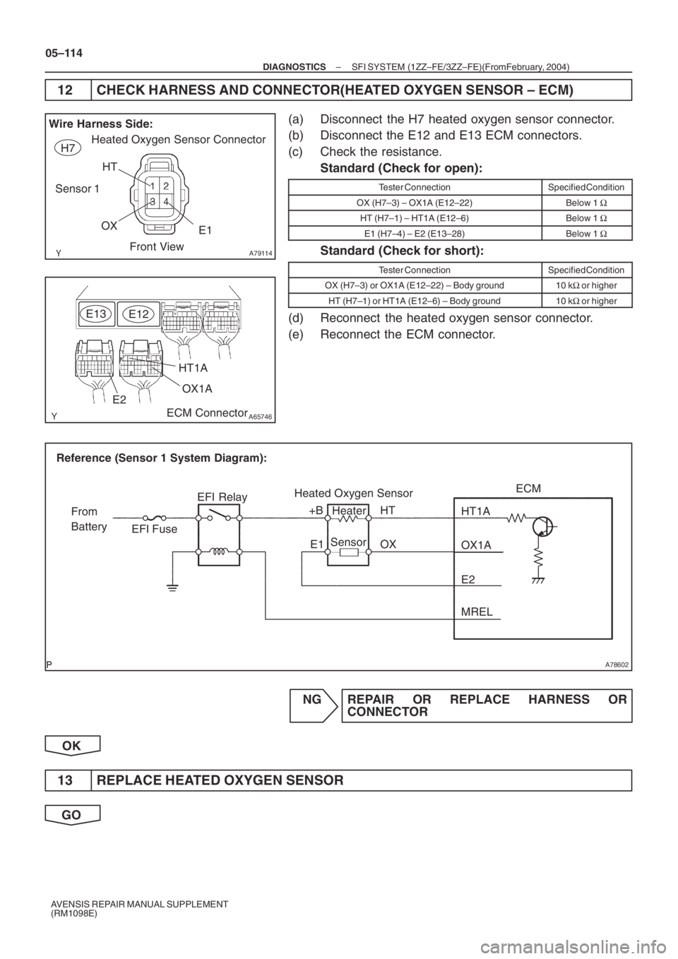
12 CHECK HARNESS AND CONNECTOR(HEATED OXYGEN SENSOR – ECM)
(a) Disconnect the H7 heated oxygen sensor connector.
(b) Disconnect the E12 and E13 ECM connectors.
(c) Check the resistance.
Standard (Check for open):
Tester ConnectionSpecified Condition
OX (H7–3) – OX1A (E12–22)Below 1 Ω
HT (H7–1) – HT1A (E12–6)Below 1 Ω
E1 (H7–4) – E2 (E13–28)Below 1 Ω
Standard (Check for short):
Tester ConnectionSpecified Condition
OX (H7–3) or OX1A (E12–22) – Body ground10 kΩ or higher
HT (H7–1) or HT1A (E12–6) – Body ground10 kΩ or higher
(d) Reconnect the heated oxygen sensor connector.
(e) Reconnect the ECM connector.
NG REPAIR OR REPLACE HARNESS OR
CONNECTOR
OK
13 REPLACE HEATED OXYGEN SENSOR
GO
Page 4923 of 5135

A78602
Reference (Sensor 2 System Diagram):Heated Oxygen Sensor
EFI Relay
Heater
Sensor OX1B
HT1BECM
From
Battery EFI Fuse
E2MREL
OX
HT
E1
+B
05–46
–
DIAGNOSTICS SFI SYSTEM (1ZZ–FE/3ZZ–FE)(From February, 2004)
AVENSIS REPAIR MANUAL SUPPLEMENT
(RM1098E)
DTC P0037 OXYGEN SENSOR HEATER CONTROL CIRCUIT LOW (BANK 1 SENSOR 2)
DTC P0038 OXYGEN SENSOR HEATER CONTROL CIRCUIT HIGH (BANK 1 SENSOR 2)
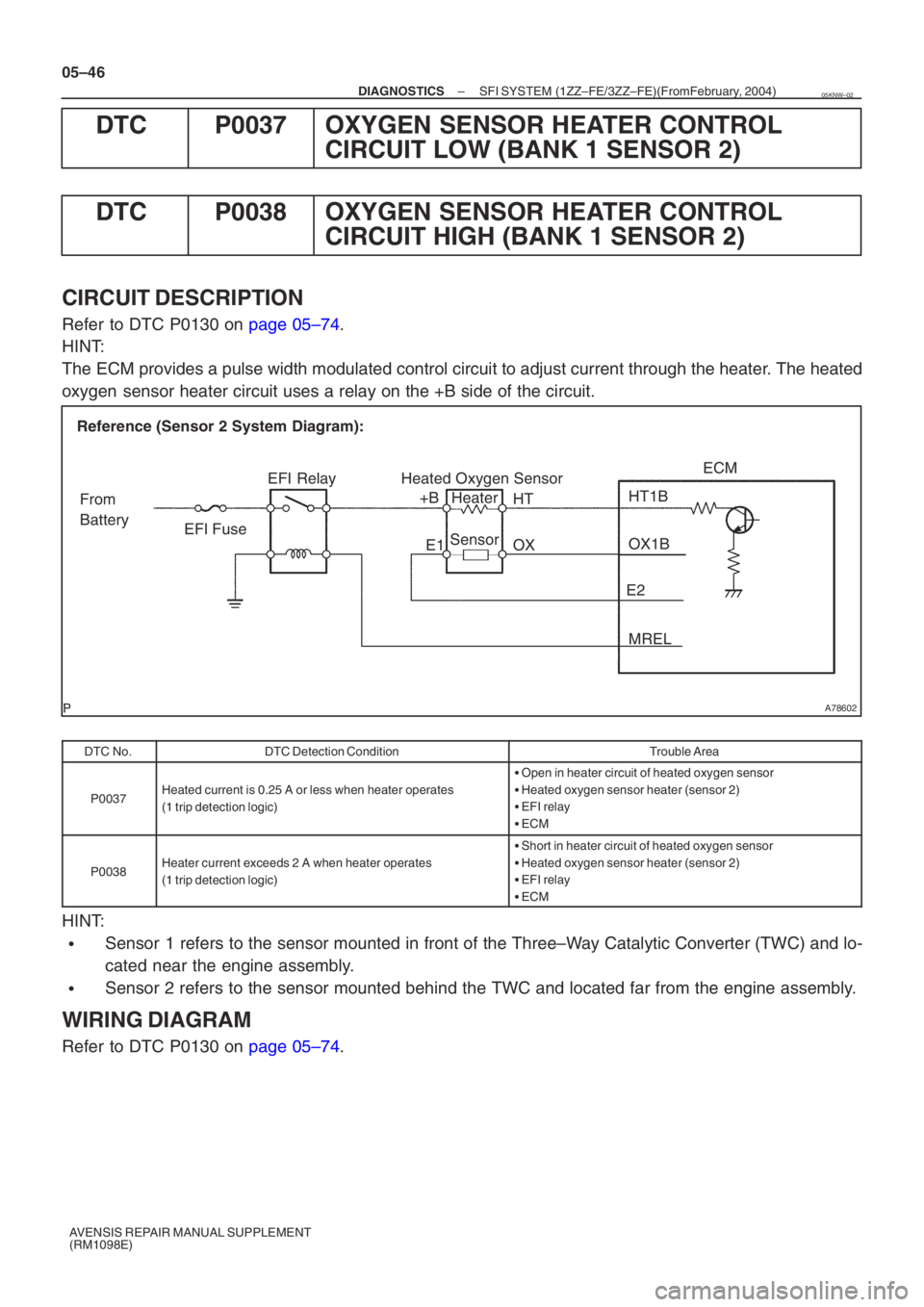
CIRCUIT DESCRIPTION
Refer to DTC P0130 on page 05–74.
HINT:
The ECM provides a pulse width modulated control circuit to adjust current \
through the heater. The heated
oxygen sensor heater circuit uses a relay on the +B side of the circuit.
DTC No.DTC Detection ConditionTrouble Area
P0037Heated current is 0.25 A or less when heater operates
(1 trip detection logic)
� Open in heater circuit of heated oxygen sensor
� Heated oxygen sensor heater (sensor 2)
� EFI relay
� ECM
P0038Heater current exceeds 2 A when heater operates
(1 trip detection logic)
�Short in heater circuit of heated oxygen sensor
� Heated oxygen sensor heater (sensor 2)
� EFI relay
� ECM
HINT:
�Sensor 1 refers to the sensor mounted in front of the Three–Way Catalytic Converter (TWC) and lo-
cated near the engine assembly.
�Sensor 2 refers to the sensor mounted behind the TWC and located far fro\
m the engine assembly.
WIRING DIAGRAM
Refer to DTC P0130 on page 05–74.
05KNW–02