Page 491 of 5135

A72920
Reference (Bank 1 Sensor 1 System Drawing)Heated Oxygen Sensor
EFI Relay
Heater
SensorOX1A HT1A
Duty
Control
ECM
From
Battery EFI Fuse
E2
EFI No. 2
Fuse
MREL
OX HT
E1
+B
±
DIAGNOSTICS SFI SYSTEM(1AZ±FSE)
05±331
AVENSIS REPAIR MANUAL (RM1018E)
CIRCUIT DESCRIPTION
Refer to DTC P0130 on page 05±363.
HINT:
The ECM provides a pulse width modulated control circuit to adjust current \
through the heater. The heated
oxygen sensor heater circuit uses a relay on the B+ side of the circuit.
DTC No.DTC Detection ConditionTrouble Area
P0031
P0037Heated current is 0.2 A or less when heater operates with +B >
10.5 V and < 11.5 V (1 trip detection logic)�Open in heater circuit of heated oxygen sensor
� Heated oxygen sensor heater
� EFI relay
P0037
P0051
P0057Heated current is 0.25 A or less when heater operates with +B
� 11.5 V (1 trip detection logic)
EFI relay
�EFI fuse
� EFI No. 2 fuse
� ECM
P0032
P0038
P0052
P0058
Heated current exceeds 2 A when heater operates.
(1 trip detection logic)�Short in heater circuit of heated oxygen sensor
� Heated oxygen sensor heater
� ECM
HINT:
�Bank 1 refers to the No. 1 and No. 4 cylinders.
�Bank 2 refers to the No. 2 and No. 3 cylinders.
�Sensor 1 refers to the sensor closest to the engine assembly.
�Sensor 2 refers to the sensor farthest away from the engine assembly.
WIRING DIAGRAM
Refer to DTC P0130 on page 05±363.
INSPECTION PROCEDURE
HINT:
�If different DTCs related to different systems that have terminal E2 as the ground terminal are output
simultaneously, terminal E2 may be open.
�Read freeze frame data using the hand±held tester. Freeze frame data records the engine conditions
when a malfunction is detected. When troubleshooting, it is useful for deter\
mining whether the vehicle
was running or stopped, the engine was warmed up or not, the air±fuel ra\
tio was lean or rich, etc. at
the time of the malfunction.
Page 553 of 5135

A76870
I13
Ignition SW
B±R
StarterECM
FL MAIN
BatterySTA E1317 B±Y
B±Y
B±W
W±B 1
2 35
9
W±B 1
1
B±R B±G 1
1B±G
4A 1A 2
DA Engine
Room
R/B No. 4Driver
Side J/B
S4
S5 14B1AM2Engine
Room
R/B No. 1 1IE41
(LHD)IP11
(RHD)B±R B±R
B±R
55
55
2DJ
IJ IK1 7B
BST
RelayDriver
Side
R/B5
4
AM2 ST2
B±Y
B±Y
A J12 B J12C J13 B J13
A J12
B±Y
(M/T) 6
6 1
2STFuse
Block
J/C
B±Y
(A/T) B±W
(A/T)
96
N1
Park/Neutral Position SwitchB±Y
± DIAGNOSTICSSFI SYSTEM (1AZ±FSE)
05±471
AVENSIS REPAIR MANUAL (RM1018E)
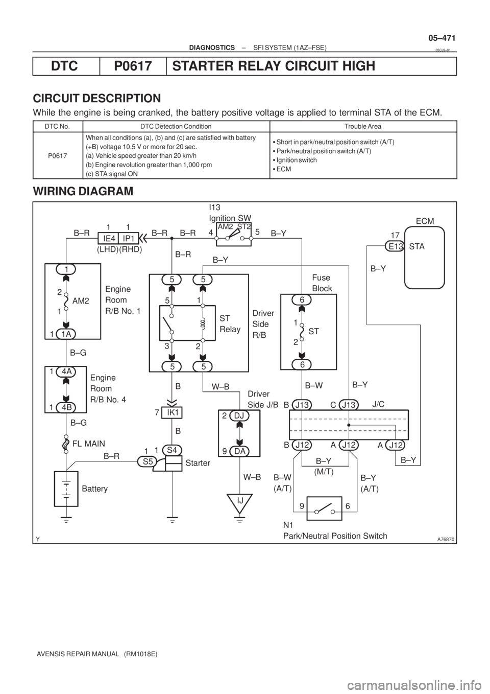
DTC P0617 STARTER RELAY CIRCUIT HIGH
CIRCUIT DESCRIPTION
While the engine is being cranked, the battery positive voltage is applied to terminal STA of the ECM.
DTC No.DTC Detection ConditionTrouble Area
P0617
When all conditions (a), (b) and (c) are satisfied with battery
(+B) voltage 10.5 V or more for 20 sec.
(a) Vehicle speed greater than 20 km/h
(b) Engine revolution greater than 1,000 rpm
(c) STA signal ON�Short in park/neutral position switch (A/T)
�Park/neutral position switch (A/T)
�Ignition switch
�ECM
WIRING DIAGRAM
05CJ9±01
Page 1126 of 5135

F44862
Engine Room R/B No.1 and Engine Room J/B No.1Power Steering
ECU Assy
Engine Room R/B No.4 EMPS Relay
W±R
FL MAIN
BatteryPIG
RLY
PGND R
R
RIE1L
1 1 1
1
1
1A
1 22 1
1
EMPS 53
51
E14
3
E15
2
E14 W±R
W±B
B±G
4B1
4A1
IM B±G 05±1076
± DIAGNOSTICSELECTRONIC MOTOR POWER STEERING SYSTEM
AVENSIS REPAIR MANUAL (RM1018E)
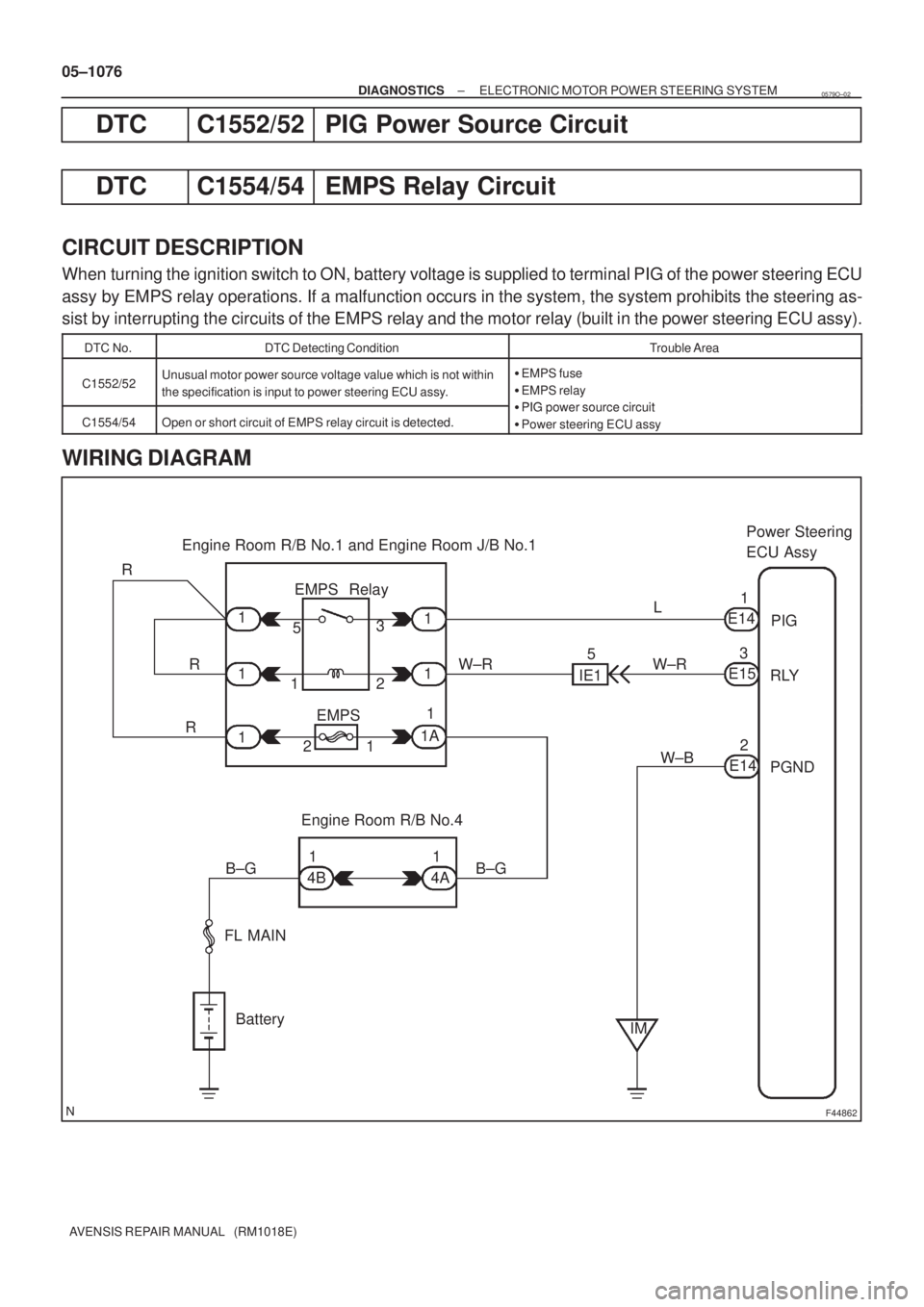
DTC C1552/52 PIG Power Source Circuit
DTC C1554/54 EMPS Relay Circuit
CIRCUIT DESCRIPTION
When turning the ignition switch to ON, battery voltage is supplied to terminal PIG of the power steering ECU
assy by EMPS relay operations. If a malfunction occurs in the system, the system prohibits the steering as-
sist by interrupting the circuits of the EMPS relay and the motor relay (built in the power steering ECU assy).
DTC No.DTC Detecting ConditionTrouble Area
C1552/52Unusual motor power source voltage value which is not within
the specification is input to power steering ECU assy.�EMPS fuse
�EMPS relay
�PIG power source circuitC1554/54Open or short circuit of EMPS relay circuit is detected.�PIG power source circuit
�Power steering ECU assy
WIRING DIAGRAM
0579O±02
Page 1130 of 5135
F44867
Engine Room R/B No. 4 I13
Ignition SWDriver Side J/B
ECU±IG
AM1
ALT
FL MAIN
BatteryIG1Relay
AM1 IG1IG
PGND R±W
R±WR±W
W±B
W±B
W±B B±G B±GG±Y
G±RJ10G
J20C
J11G
J21C
E156
E142 DB 18
DH5
DH1
DN1 DA9
4B1
4D1
IJ IM 12125 3
31J/C
(*1)
(*2)(*1)
(*2)
*1: LHD
*2: RHDPower Steering
ECU Assy
± DIAGNOSTICSELECTRONIC MOTOR POWER STEERING SYSTEM
05±1073
AVENSIS REPAIR MANUAL (RM1018E)
DTC C1551/51 IG Power Source Circuit Malfunction
CIRCUIT DESCRIPTION
The power steering ECU assy identifies ON or OFF status of the ignition switch by this circuit.
DTC No.DTC Detecting ConditionTrouble Area
C1551/51Unusual IG voltage value which exceeds the specification is
inputed to power steering ECU assy.
�ECU±IG fuse
�IG power source circuit
�Charging system
�Power steering ECU assy
WIRING DIAGRAM
0579N±02
Page 1194 of 5135
I35431
Buner Motor
Glow Plug
Surface Sensor
Temp.Control Sensor
Flame Sensor13
Power
Heater
ECU
Connector BTerminal L
of AlternatorBattery
Metering Pump
Fuse (20 A)
Vehicle Side SW 14
9
12
5
6
3
4
1
2BR
G
L±Y
L B±R
Y
L±WR
1
2
3
4 5
6
7
8W±B Connector A
IG
R±G
R±L (*1)
R±Y (*2)
R±B
W±R (*1)
Y±R (*2)
*1: TMC Made
*2: TMUK Made
± DIAGNOSTICSCOMBUSTION TYPE POWER HEATER SYSTEM
05±1165
AVENSIS REPAIR MANUAL (RM1018E)
2. DESCRIPTION OF DISPLAY AND BUTTONS
(a) AF: Current Value Malfunction (Blinking at current failure)
Diag: DTC (Example: 064 Flame sensor break)
Memory Clear button: Deletion of faulty memory (Press both buttons together for longer than 2 sec.)
> Button: Scroll up of faulty memory (The past 5 codes can be stored.)
< Button: Scroll down of faulty memory (The past 5 codes can be stored.)
3. FAULTY MEMORY
(a) The ECU is able to store upto 5 pieces of faulty memory. If it is full, the new data is written over F5.
4. WIRING DIAGRAM
Page 1198 of 5135
I35396
R±W (*2) R±W (*2, *1) G±Y (*1)
W±B (*1)
W±B
(*1) R±W (*3, *1)
R±W (*3)
R±W (*2)CB1
CK 12 Center J/BP5
Power Heater SWA/C Control Assembly
A1611
J/C
J26H
J27F3IG
IN 6
E2
A
A J16
J/C
Driver Side J/B
DC6
From
HTR Fuse
ILHOTGASIN
*1: 1CD±FTV
*2: LHD
*3: RHD
± DIAGNOSTICSAIR CONDITIONING SYSTEM
05±1159
AVENSIS REPAIR MANUAL (RM1018E)
HOT GAS HEATER SWITCH CIRCUIT
CIRCUIT DESCRIPTION
Hot gas heater performs only when its switch turns to ON and fulfill the following 6 conditions.
�Hot gas heater switch is ON.
�Recirculation damper position is FRS.
�Blower motor switch is in the position other than OFF.
�Ambient temperature varies according to the following condition;
A/C switch ONBelow ±1.5�C (32�F)
A/C switch OFFBelow 8�C (46�F)
�Air mix damper position is MAX HOT.
�Water temperature is 70�C (158�F) or less.
WIRING DIAGRAM
05C7S±01
Page 1200 of 5135
I35380
R±W
(*2)J26 J26HH
IE111
IE218
A157
MGV A/C Control Assembly
R±W
(*2)R±W R±B R±Y J/CC4
Condenser
Assembly
12
Driver Side J/B
DC6
DB5
R±W
(*1)
From
HTR Fuse
*1: LHD
*2: RHD
± DIAGNOSTICSAIR CONDITIONING SYSTEM
05±1157
AVENSIS REPAIR MANUAL (RM1018E)
HOT GAS HEATER MAGNETIC VALVE CIRCUIT
CIRCUIT DESCRIPTION
For the hot gas heater, it is necessary to fulfill the following 6 conditions.
�Hot gas heater switch is ON.
�Recirculation damper position is FRS.
�Blower motor switch is in the position other than OFF.
�Ambient temperature varies according to the following condition;
A/C switch ONBelow ±1.5�C (32�F)
A/C switch OFFBelow 8�C (46�F)
�Air mix damper position is MAX HOT.
�Water temperature is 70�C (158�F) or less.
WIRING DIAGRAM
05C7R±01
Page 1202 of 5135
I35397
R±W (*1)1
CB A15 RECR±Y A21
Air Inlet Control
Servo Motor
5 A/C Control Assembly
3 Center J/B
Driver Side J/B
From
HTR Fuse J266
CER±W (*1)
+
1
R±W (*2)
A15 FRS P±B6
R±W (*2)
J26 HHJ/C
2
R±W (*2)
R±W (*2)
DC6
*1: LHD
*2: RHD
± DIAGNOSTICSAIR CONDITIONING SYSTEM
05±1153
AVENSIS REPAIR MANUAL (RM1018E)
RECIRCULATION DAMPER SERVOMOTOR CIRCUIT
CIRCUIT DESCRIPTION
The recirculation damper servomotor is controlled by the A/C amplifier and moves the air inlet damper to the
desired position.
WIRING DIAGRAM
05C7Q±01