Page 108 of 5135

TORQUE SPECIFICATION
1ZZ±FE/3ZZ±FE:
Part TightenedN�mkgf�cmft�lbf
Radiator drain plug131309
Water pump x Cylinder")
031H4±01
03±26
± SERVICE SPECIFICATIONSCOOLING
AVENSIS REPAIR MANUAL (RM1018E)
TORQUE SPECIFICATION
1ZZ±FE/3ZZ±FE:
Part TightenedN�mkgf�cmft�lbf
Radiator drain plug131309
Water pump x Cylinder block Bolt A
Bolt B9.0
1192
11 38.0 in.lbf
8
Water inlet x Cylinder block sub±assy1111 28
Radiator x Radiator support upper1919414
1AZ±FE:
Part TightenedN�mkgf�cmft�lbf
Water pump x Cylinder block9.09280 in.�lbf
Water pump x Water pump pulley2626519
Water inlet x Cylinder block9.09280 in.�lbf
Radiator support upper x body1919414
1AZ±FSE:
Part TightenedN�mkgf�cmft�lbf
Water pump x Cylinder block9.09280 in.�lbf
Water pump x Water pump pulley2626519
Water inlet x Cylinder block9.09280 in.�lbf
Radiator support upper x body1919414
1CD±FTV:
Part TightenedN�mkgf�cmft�lbf
Drain plug1313310
Water pump x Cylinder block3132023
Fuel inlet pipe sub±assy x Common rail assy
Used pipe using SST
Used pipe not using SST
New pipe using SST
New pipe not using SST
42
46
31
34428
469
316
34731
34
23
25
Fuel inlet pipe sub±assy x Injection pump
Used pipe using SST
Used pipe not using SST
New pipe using SST
New pipe not using SST
42
46
31
34428
469
316
34731
34
23
25
Engine cover No. 1 x Cylinder head cover sub±assy8.08271 in.�lbf
Engine cover No. 1 x Intake manifold8.08271 in.�lbf
Timing belt idler Sub±assy No.1 x Cylinder block3535726
Water inlet x Cylinder block8.89078 in.�lbf
Radiator reserve tank assy x Radiator assy6.06153 in.�lbf
Fan assy w/ motor x Fan shroud assy7.57666 in.�lbf
Upper support x Body1919414
Relay box x Radiator assy5.35447 in.�lbf
Front wheel1031,05076
Page 1904 of 5135

AVENSIS REPAIR MANUAL (RM1018E)
REPLACEMENT
1.DRAIN ENGINE COOLANT(See page 16±44)
2. REMOVE RADIATOR SUPPORT OPENING COVER")
110UC±01
A79148
SST
A79143
SST
11±78
±
FUEL COMMON RAIL ASSY(1CD±FTV)
AVENSIS REPAIR MANUAL (RM1018E)
REPLACEMENT
1.DRAIN ENGINE COOLANT(See page 16±44)
2. REMOVE RADIATOR SUPPORT OPENING COVER
3. REMOVE ENGINE COVER NO.1
(a) Remove the 5 nuts and the engine cover.
4.REMOVE RADIATOR RESERVE TANK ASSY(See page 16±50) 5. REMOVE FUEL INLET PIPE SUB±ASSY
NOTICE:
After removing the fuel inlet pipe, cover the common rail
and the injection pump with vinyl tape to prevent dust from
being introduced.
(a) Using SST, remove the fuel inlet pipe from the commonrail.
SST 09023±12700
(b) Using SST, remove the fuel inlet pipe from the injection pump.
SST 09023±12700
6. REMOVE INJECTION PIPE SUB±ASSY NO.1
(a) Remove the 2 nuts and the 2 upper infection pipe clamps from the intake manifold.
(b) Using SST, remove the injection pipe from the common
rail side.
SST 09023±12700
(c) Using SST, remove the injection pipe from the injector side.
SST 09023±12700
(d) After removing the fuel pipe, to prevent dust or foreign ob- jects from being introduced, cover the common rail with
vinyl tape and protect the injector inlet with a vinyl or plas-
tic bag.
7. REMOVE INJECTION PIPE SUB±ASSY NO.2 SST 09023±12700
HINT:
Perform the same procedures as injection pipe No. 1.
8. REMOVE INJECTION PIPE SUB±ASSY NO.3 SST 09023±12700
HINT:
Perform the same procedures as injection pipe No. 1.
Page 1907 of 5135

SST
±
FUEL COMMON RAIL ASSY(1CD±FTV)
11±81
AVENSIS REPAIR MANUAL (RM1018E)
19.INSTALL FUEL INLET PIPE SUB±ASSY
NOTICE:
�In case of having the common rail replaced, must")
A79149
30 cm
(11.81 in.)
SST
±
FUEL COMMON RAIL ASSY(1CD±FTV)
11±81
AVENSIS REPAIR MANUAL (RM1018E)
19.INSTALL FUEL INLET PIPE SUB±ASSY
NOTICE:
�In case of having the common rail replaced, must re-
place fuel inlet pipe, too.
�When assembling the pipe, perform the operation
with the engine cold under room temperature.
(a)Temporarily install the fuel inlet pipe.
(b)Using SST, tighten the nut of the fuel inlet pipe to the com-
mon rail side.
SST09023±12700
Torque:
42 N�m (428 kgf �cm, 31 ft �lbf) for a used pipe using SST
46 N �m (469 kgf �cm, 34 ft �lbf) for a used pipe not using
SST
31 N �m (316 kgf �cm, 23 ft �lbf) for a new pipe using SST
34 N �m (347 kgf �cm, 25 ft �lbf) for a new pipe not using
SST
HINT:
�Use a torque wrench with a fulcrum length of 30 cm
(11.81 in.)
�Check if the used pipe has deflection or is installed prop-
erly after inlet pipe is reassembled. If there is deflection
or if it can not be installed properly, replace the used pipe
with a new pipe.
(c)Using SST, tighten the nut of the fuel inlet pipe to the injec-
tion pump side.
SST09023±12700
Torque:
42 N�m (428 kgf �cm, 31 ft �lbf) for a used pipe using SST
46 N �m (469 kgf �cm, 34 ft �lbf) for a used pipe not using
SST
31 N �m (316 kgf �cm, 23 ft �lbf) for a new pipe using SST
34 N �m (347 kgf �cm, 25 ft �lbf) for a new pipe not using
SST
HINT:
�Use a torque wrench with a fulcrum length of 30 cm
(11.81 in.)
�Check if the used pipe has deflection or is installed prop-
erly after inlet pipe is reassembled. If there is deflection
or if it can not be installed properly, replace the used pipe
with a new pipe.
20.INSTALL RADIATOR RESERVE TANK ASSY(See page 16±50)
21. INSTALL ENGINE COVER NO.1 Torque: 8.0 N �m (82 kgf �cm, 71 in. �lbf)
22.ADD ENGINE COOLANT(See page 16±44)
23.CHECK FOR ENGINE COOLANT LEAKS(See page 16±37)
24.CHECK FOR FUEL LEAKS(See page 11±60)
Page 1908 of 5135
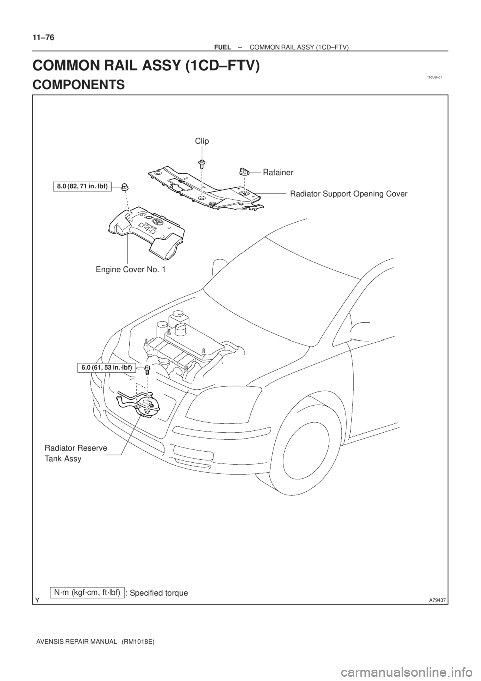
110UB±01
A79437
8.0 (82, 71 in.�lbf)
Engine Cover No. 1Radiator Support Opening Cover
N´m (kgf´cm, ft´lbf)
: Specified torque
6.0 (61, 53 in.�lbf)
Radiator Reserve
Tank Assy
Clip
Ratainer
11±76
± FUELCOMMON RAIL ASSY (1CD±FTV)
AVENSIS REPAIR MANUAL (RM1018E)
COMMON RAIL ASSY (1CD±FTV)
COMPONENTS
Page 1910 of 5135

11±69
AVENSIS REPAIR MANUAL (RM1018E)
REPLACEMENT
1.REMOVE FRONT WHEEL RH
2.DRAIN ENGINE COOLANT(See page 16±44)
3.REMOVE ENGINE UN")
110UA±01
A15950
±
FUEL INJECTION OR SUPPLY PUMP ASSY(1CD±FTV)
11±69
AVENSIS REPAIR MANUAL (RM1018E)
REPLACEMENT
1.REMOVE FRONT WHEEL RH
2.DRAIN ENGINE COOLANT(See page 16±44)
3.REMOVE ENGINE UNDER COVER SUB±ASSY NO.1
4.REMOVE ENGINE UNDER COVER RH
5.REMOVE RADIATOR SUPPORT OPENING COVER
6.REMOVE ENGINE ROOM COVER SIDE
7.REMOVE AIR CLEANER ASSY (See page 11±60)
8.REMOVE ENGINE COVER NO.1
(a)Remove the 5 nuts and the engine cover.
9.REMOVE RADIATOR RESERVE TANK ASSY(See page 16±50)
10.DISCONNECT RADIATOR HOSE OUTLET
(a)Disconnect the radiator hose outlet from the water inlet.
11.REMOVE V (COOLER COMPRESSOR TO CRANKSHAFT PULLEY) BELT NO.1
(See page 14±269)
12.REMOVE GENERATOR V BELT (See page 14±269)
13.REMOVE INJECTOR DRIVER
(a)Remove the 2 nuts which are used to secure the injector driver.
(b)Disconnect the injector driver connector and the harness clamp.
(c)Remove the injector driver.
14.REMOVE ENGINE MOUNTING INSULATOR SUB±ASSY RH(See page 14±307)
15.REMOVE CRANKSHAFT PULLEY(See page 14±307)
SST09213±54015 (90105±08076), 09330±00021, 09950±50013 (0995\
1±05010, 09952±05010, 09953±05020, 09954±05031)
16.REMOVE IDLER PULLEY SUB±ASSY
(a)Remove the bolt and washer, then remove the idler pulley.
17.REMOVE TIMING BELT NO.2 COVER(See page 14±307)
18.REMOVE TIMING BELT NO.1 COVER(See page 14±307)
19. REMOVE TIMING BELT GUIDE
20. REMOVE TRANSVERSE ENGINE ENGINE MOUNTING BRACKET
(a) Remove the 6 bolts and the engine mounting bracket.
21.SET NO. 1 CYLINDER TO TDC/COMPRESSION(See page 14±307)
22.REMOVE TIMING CHAIN COVER PLATE(See page 14±307)
23.REMOVE TIMING BELT(See page 14±307)
Page 1916 of 5135

11±75
AVENSIS REPAIR MANUAL (RM1018E)
52.INSTALL TIMING BELT GUIDE(See page 14±307)
53.INSTALL TIMING BELT NO.1 COVER(See page 14±307)
54.INSTALL")
±
FUEL INJECTION OR SUPPLY PUMP ASSY (1CD±FTV)
11±75
AVENSIS REPAIR MANUAL (RM1018E)
52.INSTALL TIMING BELT GUIDE(See page 14±307)
53.INSTALL TIMING BELT NO.1 COVER(See page 14±307)
54.INSTALL TIMING BELT NO.2 COVER(See page 14±307)
55. INSTALL IDLER PULLEY SUB±ASSY
Torque: 40 N �m (408 kgf �cm, 30 ft �lbf)
56.INSTALL CRANKSHAFT PULLEY(See page 14±307) SST 09213±54015 (90105±08076), 09330±00021
57.INSTALL ENGINE MOUNTING INSULATOR SUB±ASSY RH(See page 14±307)
58. INSTALL INJECTOR DRIVER Torque: 5.0 N �m (51 kgf �cm, 44 in. �lbf)
59. ADJUST V (COOLER COMPRESSOR TO CRANKSHAFT PULLEY) BELT NO.1 (See page 14±269)
60.INSTALL RADIATOR RESERVE TANK ASSY(See page 16±50)
61. INSTALL ENGINE COVER NO.1 Torque: 8.0 N �m (82 kgf �cm, 71 in. �lbf)
62.INSTALL AIR CLEANER ASSY (See page 11±60)
63. INSTALL FRONT WHEEL RH
Torque: 103 N �m (1,050 kgf �cm, 76 ft �lbf)
64.ADD ENGINE COOLANT(See page 16±44)
65.CHECK FOR ENGINE COOLANT LEAKS(See page 16±37)
66.CHECK FOR FUEL LEAKS(See page 11±60)
Page 1917 of 5135
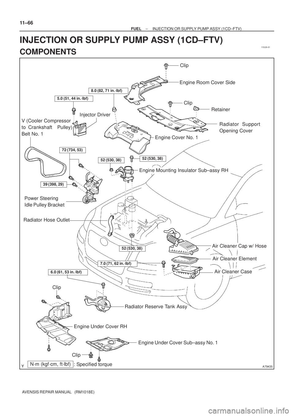
110U9±01
A79435
Air Cleaner Cap w/ Hose
Air Cleaner Element
Air Cleaner Case
7.0 (71, 62 in.�lbf)
N´m (kgf´cm, ft´lbf)
: Specified torque
Radiator Hose Outlet
Clip
Engine Room Cover Side
Clip
Retainer
Radiator Support
Opening Cover
8.0 (82, 71 in.�lbf)
5.0 (51, 44 in.�lbf)
V (Cooler Compressor
to Crankshaft Pulley)
Belt No. 1
Injector Driver
72 (734, 53)
52 (530, 38)52 (530, 38)
Engine Cover No. 1
Engine Mounting Insulator Sub±assy RH
39 (398, 29)
Power Steering
Idle Pulley Bracket
52 (530, 38)
Clip
Engine Under Cover RH
Engine Under Cover Sub±assy No. 1
Clip
Radiator Reserve Tank Assy
6.0 (61, 53 in.�lbf)
11±66
± FUELINJECTION OR SUPPLY PUMP ASSY (1CD±FTV)
AVENSIS REPAIR MANUAL (RM1018E)
INJECTION OR SUPPLY PUMP ASSY (1CD±FTV)
COMPONENTS
Page 2085 of 5135
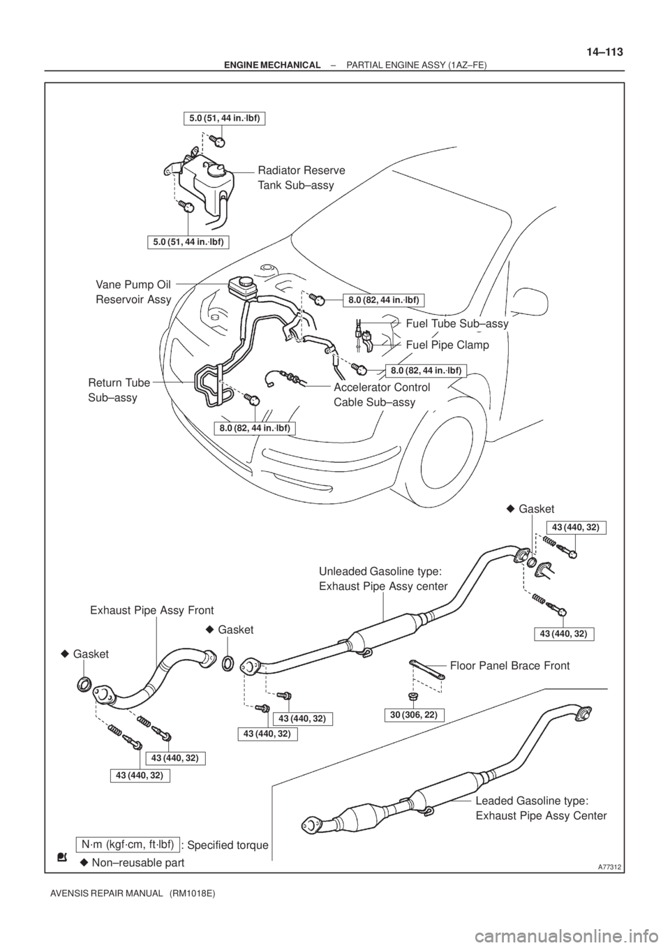
A77312
30 (306, 22)
Radiator Reserve
Tank Sub±assy
Fuel Tube Sub±assy
Unleaded Gasoline type:
Exhaust Pipe Assy center
� Gasket
� Gasket� Gasket
Floor Panel Brace Front
Leaded Gasoline type:
Exhaust Pipe Assy Center Vane Pump Oil
Reservoir Assy
Accelerator Control
Cable Sub±assy
Fuel Pipe Clamp
Exhaust Pipe Assy Front
8.0 (82, 44 in.�lbf)
8.0 (82, 44 in.�lbf)
8.0 (82, 44 in.�lbf)
Return Tube
Sub±assy
43 (440, 32)
5.0 (51, 44 in.�lbf)
N´m (kgf´cm, ft´lbf)
: Specified torque
� Non±reusable part
43 (440, 32)
43 (440, 32)
43 (440, 32)
43 (440, 32)
43 (440, 32)
5.0 (51, 44 in.�lbf)
± ENGINE MECHANICALPARTIAL ENGINE ASSY (1AZ±FE)
14±113
AVENSIS REPAIR MANUAL (RM1018E)