Page 259 of 5135

A18294
OCV+OCV±
ECM Connector
E13
A58701A58701
OCV Signal Waveform1 m sec./Division 5 V/
Division
GND
(A)(A)(A)
±
DIAGNOSTICS SFI SYSTEM(1ZZ±FE/3ZZ±FE)
05±113
AVENSIS REPAIR MANUAL (RM1018E)
2PERFORM ACTIVE TEST BY HAND±HELD TESTER(OPERATE OF OCV)
(a)Start the engine and warm it up.
(b)Connect the hand±held tester and select VVT from the ACTIVE TEST menu\
.
(c)Check the engine speed while operating the OCV by the hand±held teste\
r.
OCV is OFF: Normal engine speed
OCV is ON: Rough idle or engine stall
HINT:
DTC P1349 is also output when a foreign object is detected in some parts\
of the system in engine oil, and
then the system returns to normal in a short time. There is also no problem \
on the VVT as the oil filter should
catch the foreign object in engine oil.
OKVVT SYSTEM OK
NG
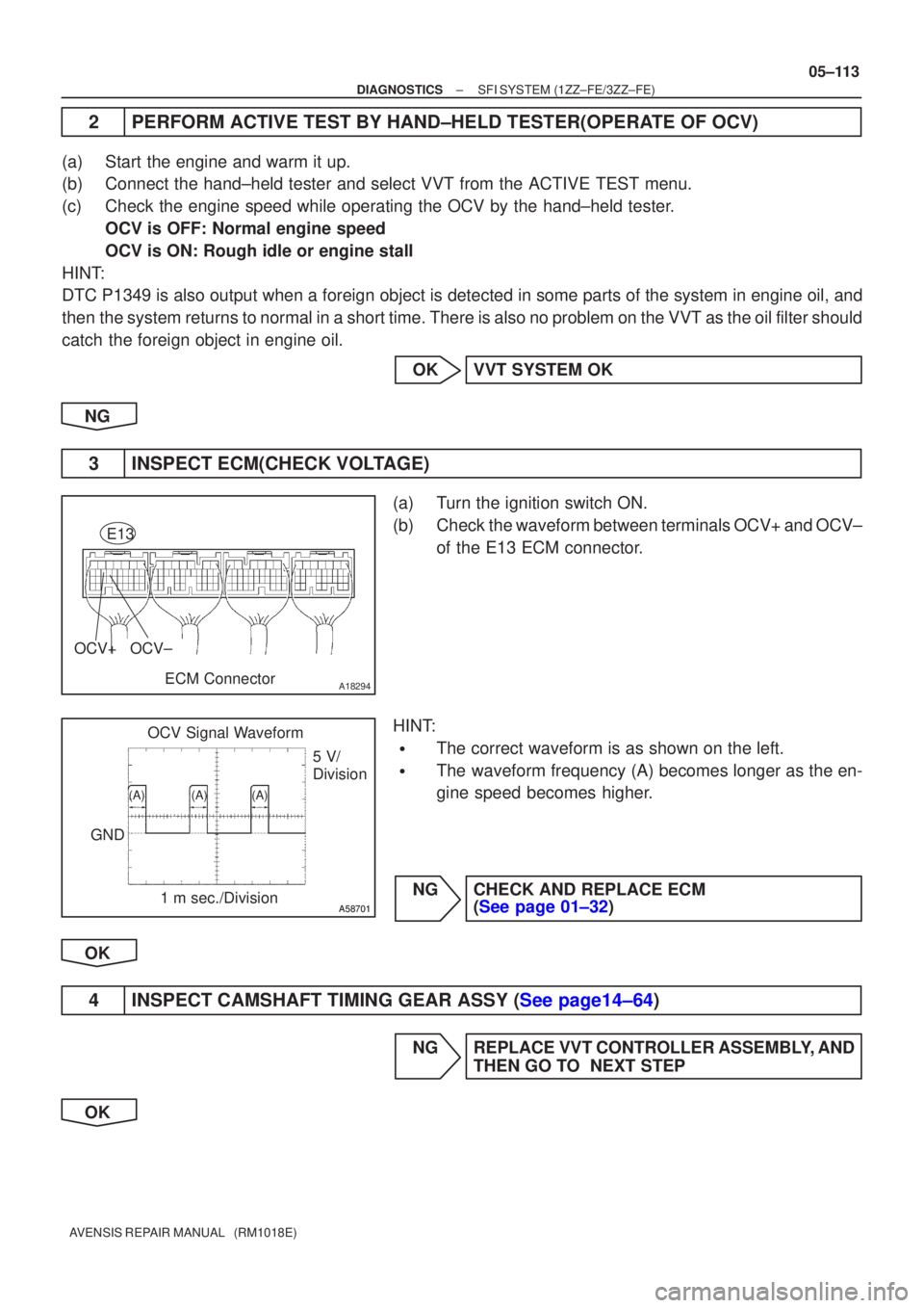
3INSPECT ECM(CHECK VOLTAGE)
(a)Turn the ignition switch ON.
(b)Check the waveform between terminals OCV+ and OCV± of the E13 ECM connector.
HINT:
�The correct waveform is as shown on the left.
�The waveform frequency (A) becomes longer as the en-
gine speed becomes higher.
NGCHECK AND REPLACE ECM (See page 01±32)
OK
4INSPECT CAMSHAFT TIMING GEAR ASSY (See page14±64)
NG REPLACE VVT CONTROLLER ASSEMBLY, AND THEN GO TO NEXT STEP
OK
Page 638 of 5135
A80985
A66061
A66063
A66064
A66065
± DIAGNOSTICSECD SYSTEM (1CD±FTV)
05±537
AVENSIS REPAIR MANUAL (RM1018E)
(d) Enter ºDIAGNOSIS / OBD/MOBD / DIAGNOSTIC MENU
ECDº and select the item ºINJECTOR COMP.º
(e) Press the ºENTERº button on the hand±held tester.
(f) Press the ºENTERº button again.
(g) Select ºREAD COMP VALUEº and press the ºENTERº
button.
(h) Select a cylinder number which you want to read the com-
pensation code.
(i) Press the ºENTERº button.
(j) Wait until the next screen comes up.
Page 639 of 5135
A66066
A66067
05±538
± DIAGNOSTICSECD SYSTEM (1CD±FTV)
AVENSIS REPAIR MANUAL (RM1018E)
(k) Confirm the 30±digit±alphanumeric code which is dis-
played on the hand±held tester. This is the injection com-
pensation code for the cylinder.
HINT:
The code shown in the illustration is an example.
(l) Press the ºENTERº button to exit this screen.
(m) Press the ºNOº button to complete the confirmation.
HINT:
�If you want to read other compensation codes for other
cylinders, press the ºYESº button instead of ºNO.º
�By pressing the ºNOº button, the hand±held tester returns
to the ºDIAGNOSTIC MENU ECDº screen.
Page 641 of 5135
A80985
A66061
A66062
A66068
A66069
05±540
± DIAGNOSTICSECD SYSTEM (1CD±FTV)
AVENSIS REPAIR MANUAL (RM1018E)
(d) Enter ºDIAGNOSIS / OBD/MOBD / DIAGNOSTIC MENU
ECDº and select the item ºINJECTOR COMP.º
(e) Press the ºENTERº button on the hand±held tester.
(f) Press the ºEnterº button again.
(g) Select ºSET COMP VALUEº and press the ºENTERº but-
ton.
(h) Press the ºENTERº button.
(i) Select a cylinder number which you want to register the
compensation code.
(j) Press the ºENTERº button.
Page 643 of 5135

A66074
A66289
Inside
05±542
±
DIAGNOSTICS ECD SYSTEM(1CD±FTV)
AVENSIS REPAIR MANUAL (RM1018E)
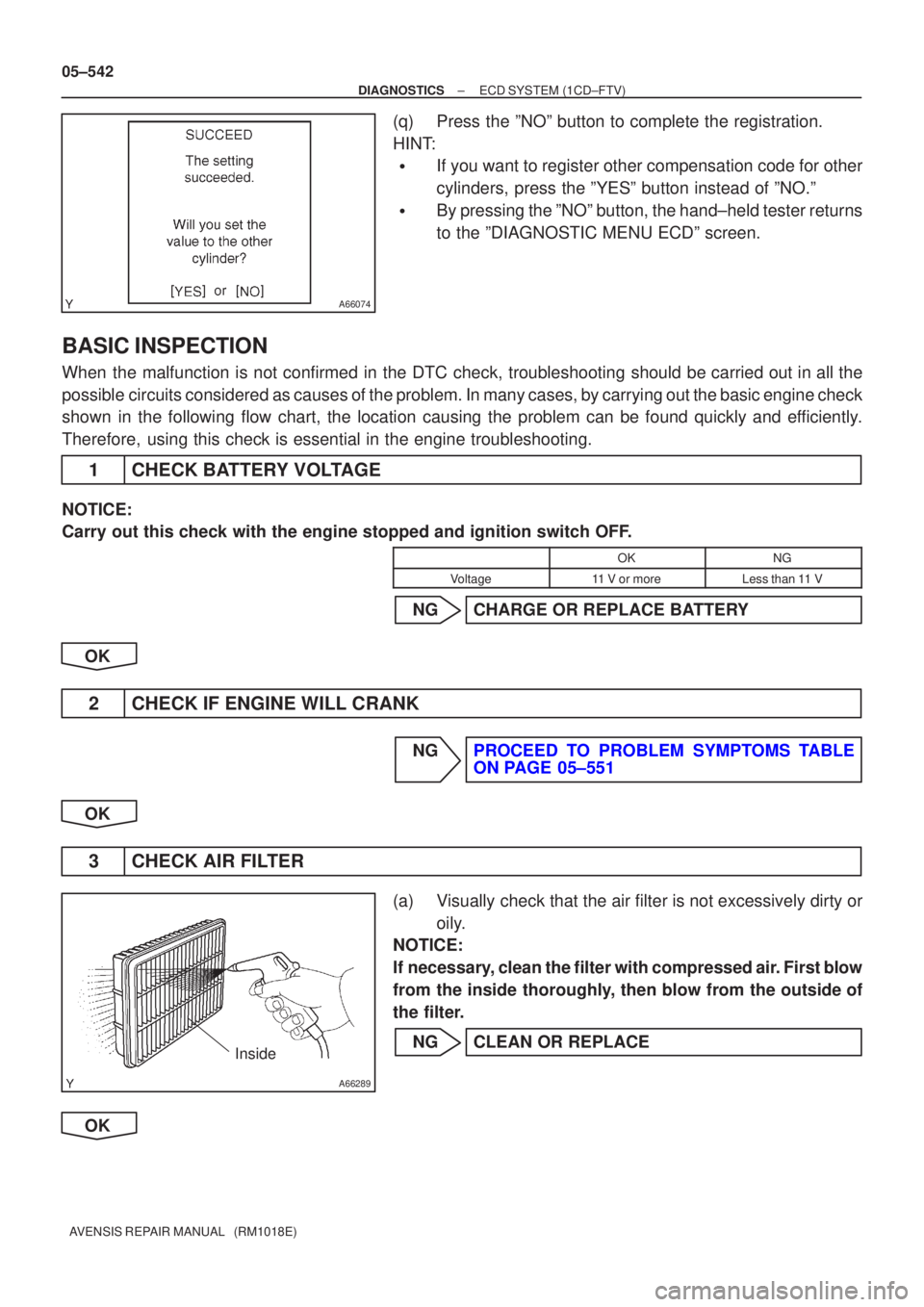
(q)Press the ºNOº button to complete the registration.
HINT:
�If you want to register other compensation code for other
cylinders, press the ºYESº button instead of ºNO.º
�By pressing the ºNOº button, the hand±held tester returns
to the ºDIAGNOSTIC MENU ECDº screen.
BASIC INSPECTION
When the malfunction is not confirmed in the DTC check, troubleshooting shou\
ld be carried out in all the
possible circuits considered as causes of the problem. In many cases, by carrying out the basic engine check
shown in the following flow chart, the location causing the problem can be found quickly and efficiently.
Therefore, using this check is essential in the engine troubleshooting.
1CHECK BATTERY VOLTAGE
NOTICE:
Carry out this check with the engine stopped and ignition switch OFF.
OKNG
Voltage11 V or moreLess than 11 V
NGCHARGE OR REPLACE BATTERY
OK
2CHECK IF ENGINE WILL CRANK
NGPROCEED TO PROBLEM SYMPTOMS TABLE ON PAGE 05±551
OK
3 CHECK AIR FILTER
(a) Visually check that the air filter is not excessively dirty or oily.
NOTICE:
If necessary, clean the filter with compressed air. First blow
from the inside thoroughly, then blow from the outside of
the filter.
NG CLEAN OR REPLACE
OK
Page 927 of 5135
G23367
Tester menu flow:
± DIAGNOSTICSELECTRONIC CONTROLLED AUTOMATIC
TRANSAXLE [ECT] (U241E(1AZ±FE))05±875
AVENSIS REPAIR MANUAL (RM1018E)
11. RESET MEMORY
CAUTION:
Perform the RESET MEMORY (AT initialization) when replacing the automatic transaxle assy, engine
assy or ECM.
NOTICE:
Hand±held tester only
(a) Turn the ignition switch to OFF.
(b) Connect the hand±held tester to the DLC3.
(c) Turn the ignition switch to ON.
(d) Perform the reset memory procedure from the ENGINE menu.
CAUTION:
After performing the RESET MEMORY, be sure to perform the ROAD TEST described earlier.
Page 951 of 5135
G23367
Tester menu flow: 05±930
± DIAGNOSTICSELECTRONIC CONTROLLED AUTOMATIC
TRANSAXLE [ECT] (U241E(1AZ±FSE))
AVENSIS REPAIR MANUAL (RM1018E)
11. RESET MEMORY
CAUTION:
Perform the RESET MEMORY (AT initialization) when replacing the automatic transaxle assy, engine
assy or ECM.
NOTICE:
Hand±held tester only
(a) Turn the ignition switch to OFF.
(b) Connect the hand±held tester to the DLC3.
(c) Turn the ignition switch to ON.
(d) Perform the reset memory procedure from the ENGINE menu.
CAUTION:
After performing the RESET MEMORY, be sure to perform the ROAD TEST described earlier.
Page 1513 of 5135

I34690
ºINFOº
Switch
Navigation Controller Assy:
I35902
05±1440
± DIAGNOSTICSNAVIGATION SYSTEM
AVENSIS REPAIR MANUAL (RM1018E)
(a) Start±up and finishing of the diagnosis.
HINT:
Before starting the diagnosis system, make sure that the map
appears on the screen after turning the IG switch ON.
If not, some items cannot be checked.
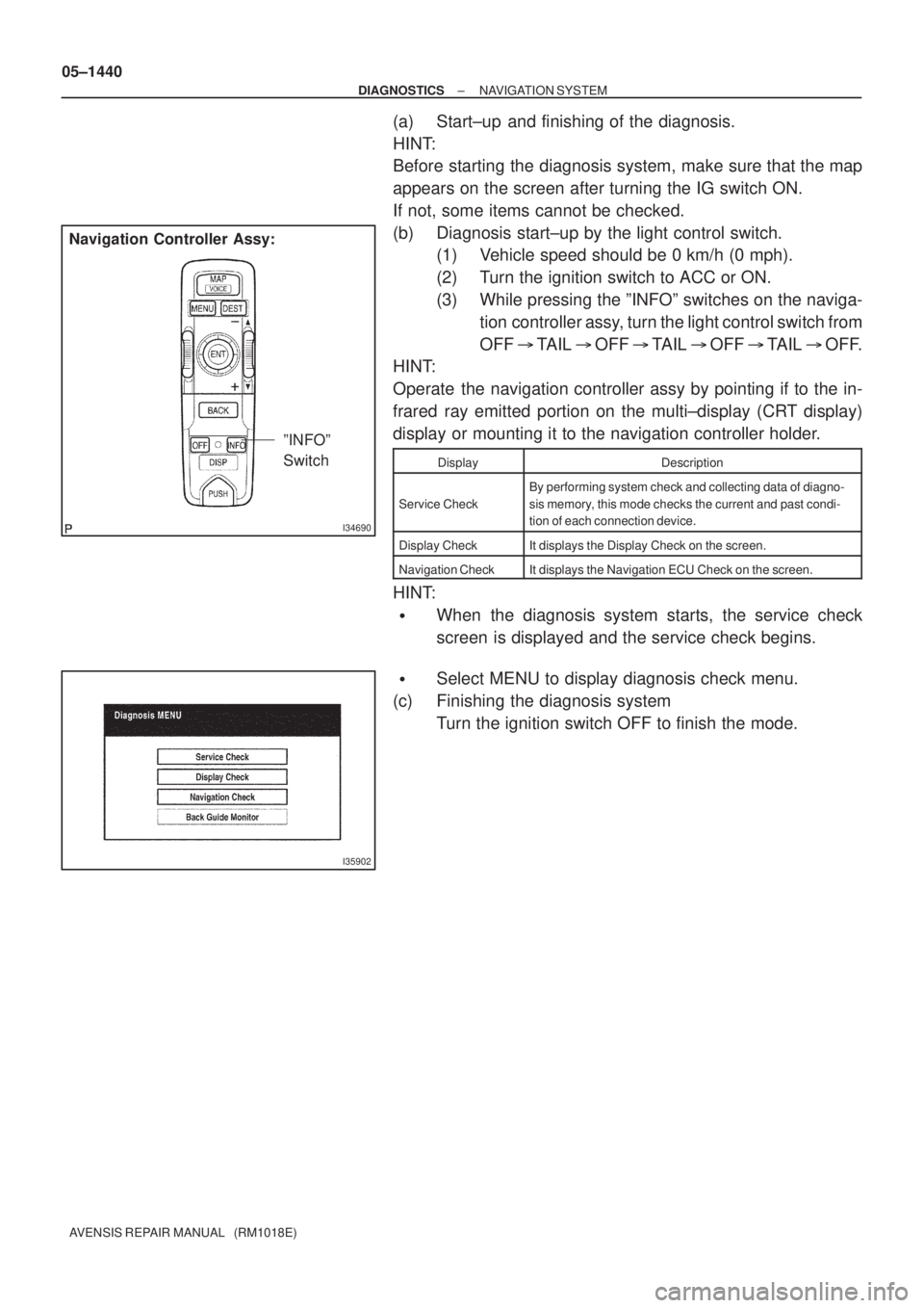
(b) Diagnosis start±up by the light control switch.
(1) Vehicle speed should be 0 km/h (0 mph).
(2) Turn the ignition switch to ACC or ON.
(3) While pressing the ºINFOº switches on the naviga-
tion controller assy, turn the light control switch from
OFF � TAIL � OFF � TAIL � OFF � TAIL � OFF.
HINT:
Operate the navigation controller assy by pointing if to the in-
frared ray emitted portion on the multi±display (CRT display)
display or mounting it to the navigation controller holder.
DisplayDescription
Service Check
By performing system check and collecting data of diagno-
sis memory, this mode checks the current and past condi-
tion of each connection device.
Display CheckIt displays the Display Check on the screen.
Navigation CheckIt displays the Navigation ECU Check on the screen.
HINT:
�When the diagnosis system starts, the service check
screen is displayed and the service check begins.
�Select MENU to display diagnosis check menu.
(c) Finishing the diagnosis system
Turn the ignition switch OFF to finish the mode.