Page 4917 of 5135
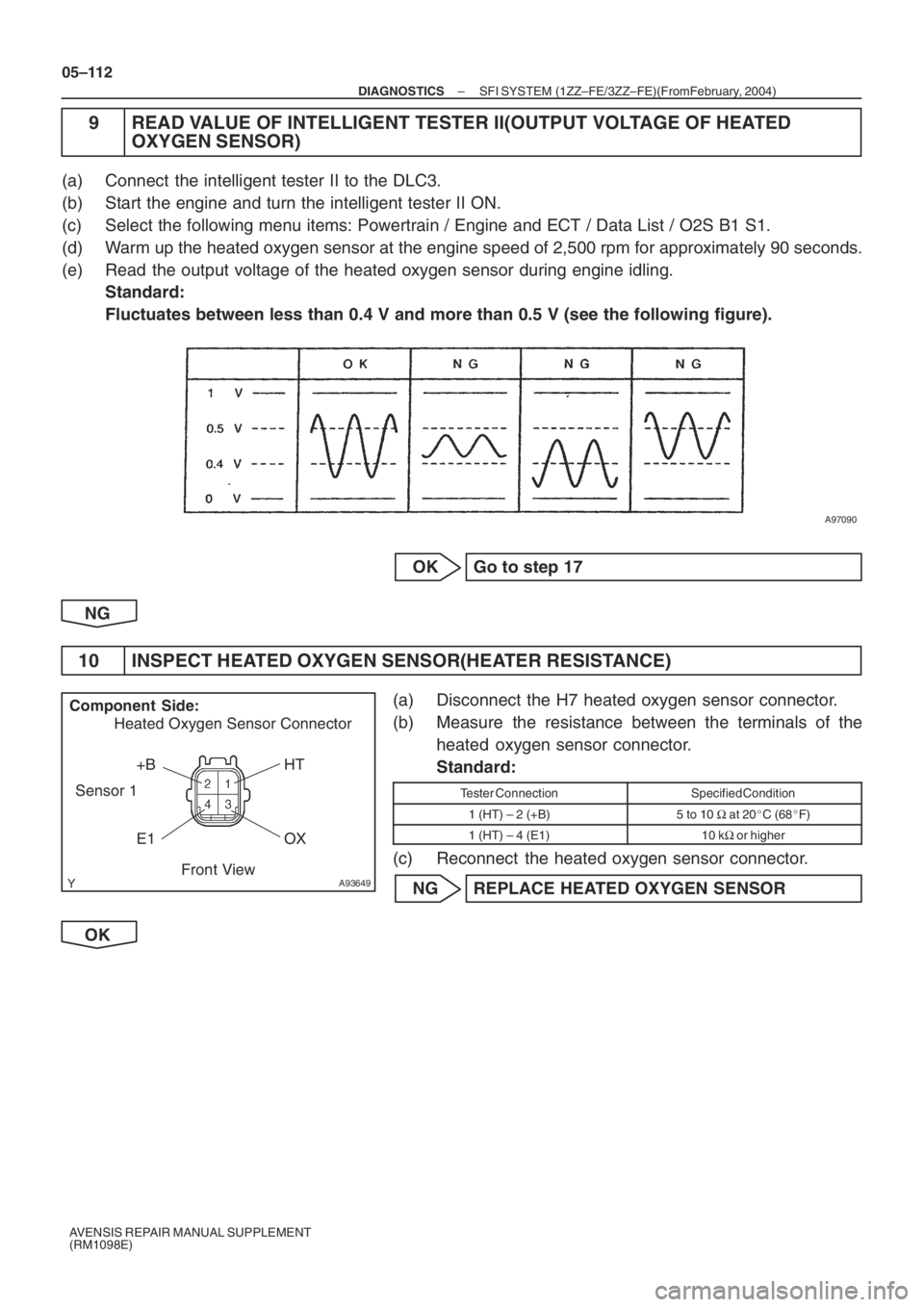
A97090
A93649
+B HT
E1 Component Side:
Front View Heated Oxygen Sensor Connector
Sensor 1
OX
05–112
– DIAGNOSTICSSFI SYSTEM (1ZZ–FE/3ZZ–FE)(From February, 2004)
AVENSIS REPAIR MANUAL SUPPLEMENT
(RM1098E)
9 READ VALUE OF INTELLIGENT TESTER II(OUTPUT VOLTAGE OF HEATED
OXYGEN SENSOR)
(a) Connect the intelligent tester II to the DLC3.
(b) Start the engine and turn the intelligent tester II ON.
(c) Select the following menu items: Powertrain / Engine and ECT / Data List / O2S B1 S1.
(d) Warm up the heated oxygen sensor at the engine speed of 2,500 rpm for approximately 90 seconds.
(e) Read the output voltage of the heated oxygen sensor during engine idling.
Standard:
Fluctuates between less than 0.4 V and more than 0.5 V (see the following figure).
OK Go to step 17
NG
10 INSPECT HEATED OXYGEN SENSOR(HEATER RESISTANCE)
(a) Disconnect the H7 heated oxygen sensor connector.
(b) Measure the resistance between the terminals of the
heated oxygen sensor connector.
Standard:
Tester ConnectionSpecified Condition
1 (HT) – 2 (+B)5 to 10 Ω at 20�C (68�F)
1 (HT) – 4 (E1)10 kΩ or higher
(c) Reconnect the heated oxygen sensor connector.
NG REPLACE HEATED OXYGEN SENSOR
OK
Page 4921 of 5135

05–116
–
DIAGNOSTICS SFI SYSTEM (1ZZ–FE/3ZZ–FE)(From February, 2004)
AVENSIS REPAIR MANUAL SUPPLEMENT
(RM1098E)
15 CHECK IF DTC OUTPUT RECURS(DTC P0171 AND/OR P0172)
(a) Connect the intelligent tester II to the DLC3.
(b) Turn the ignition switch to ON and turn the intelligent tester ll ON.
(c) Select the following menu items: Powertrain / Engine and ECT / DTC.
(d) Read DTCs. Result:
Display (DTC Output)Proceed To
No outputA
P0171 and/or P0172B
B REPLACE ECM AND PERFORM CONFIRMA- TION DRIVING PATTERN
(Refer to step 14)
A
16 CONFIRM IF VEHICLE HAS RUN OUT OF FUEL IN PAST
NO CHECK FOR INTERMITTENT PROBLEMS (See page 05–9 )
YES
DTCS ARE CAUSED BY RUNNING OUT OF FUEL (DTCS P0171 AND/OR P0172)
17 PERFORM CONFIRMATION DRIVING PATTERN
HINT:
Clear all DTCs prior to performing the confirmation driving pattern (re\
fer to step 14). GO
18 CHECK IF DTC OUTPUT RECURS(DTC P0171 AND/OR P0172)
(a) Connect the intelligent tester II to the DLC3.
(b) Turn the ignition switch to ON and turn the intelligent tester ll ON.
(c) Select the following menu items: Powertrain / Engine and ECT / DTC.
(d) Read DTCs. Result:
Display (DTC Output)Proceed To
P0171 and/or P0172A
No outputB
B Go to step 22
A
Page 4922 of 5135
–
DIAGNOSTICS SFI SYSTEM (1ZZ–FE/3ZZ–FE)(From February, 2004)
05–117
AVENSIS REPAIR MANUAL SUPPLEMENT
(RM1098E)
19 REPLACE HEATED OXYGEN SENSOR
GO
20 PERFORM CONFIRMATION DRIVING PATTERN
HINT:
Clear all DTCs prior to performing the confirmation driving pattern (refer t\
o step 14).
GO
21 CHECK IF DTC OUTPUT RECURS(DTC P0171 AND/OR P0172)
(a) Connect the intelligent tester II to the DLC3.
(b) Turn the ignition switch to ON and turn the intelligent tester ll ON.
(c) Select the following menu items: Powertrain / Engine and ECT / DTC.
(d) Read DTCs. Result:
Display (DTC Output)Proceed To
No outputA
P0171 and/or P0172B
B REPLACE ECM AND PERFORM CONFIRMA- TION DRIVING PATTERN
(Refer to step 14)
A
22 CONFIRM IF VEHICLE HAS RUN OUT OF FUEL IN PAST
NO CHECK FOR INTERMITTENT PROBLEMS
( See page 05–9 )
YES
DTCS ARE CAUSED BY RUNNING OUT OF FUEL (DTCS P0171 AND/OR P0172)
Page 4947 of 5135
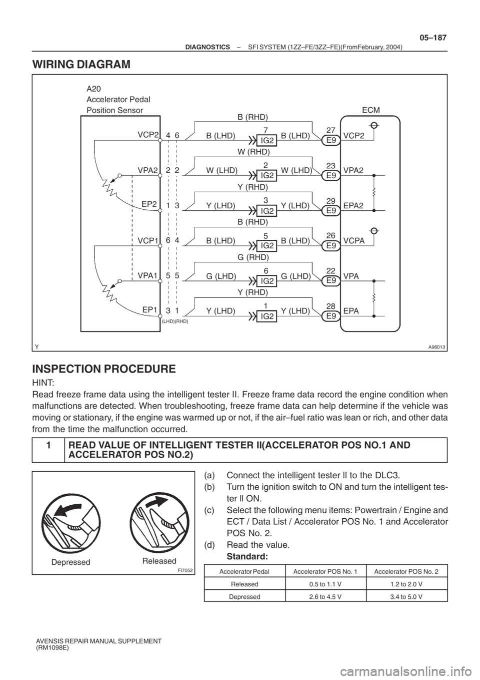
A96013
A20
Accelerator Pedal
Position Sensor
VPA2
VPA1
EP1 VCP1 VCP2
6
EP2E927ECM
VPA2
VPA
EPA VCPA EPA2 VCP2 4
22
13
64
55
31
(LHD)(RHD)
B (RHD)
W (RHD)
Y (RHD)
B (RHD)
G (RHD)
Y (RHD)G (LHD) W (LHD) W (LHD)
Y (LHD) Y (LHD) B (LHD) B (LHD)
B (LHD)
Y (LHD) Y (LHD) G (LHD) B (LHD)IG2
IG2
IG2
IG2
IG2
IG27
2
3
5
6
1
E928 E922 E926 E929 E923
FI7052DepressedReleased
– DIAGNOSTICSSFI SYSTEM (1ZZ–FE/3ZZ–FE)(From February, 2004)
05–187
AVENSIS REPAIR MANUAL SUPPLEMENT
(RM1098E)
WIRING DIAGRAM
INSPECTION PROCEDURE
HINT:
Read freeze frame data using the intelligent tester II. Freeze frame data record the engine condition when
malfunctions are detected. When troubleshooting, freeze frame data can help determine if the vehicle was
moving or stationary, if the engine was warmed up or not, if the air–fuel ratio was lean or rich, and other data
from the time the malfunction occurred.
1 READ VALUE OF INTELLIGENT TESTER II(ACCELERATOR POS NO.1 AND
ACCELERATOR POS NO.2)
(a) Connect the intelligent tester ll to the DLC3.
(b) Turn the ignition switch to ON and turn the intelligent tes-
ter ll ON.
(c) Select the following menu items: Powertrain / Engine and
ECT / Data List / Accelerator POS No. 1 and Accelerator
POS No. 2.
(d) Read the value.
Standard:
Accelerator PedalAccelerator POS No. 1Accelerator POS No. 2
Released0.5 to 1.1 V1.2 to 2.0 V
Depressed2.6 to 4.5 V3.4 to 5.0 V
Page 4951 of 5135
–
DIAGNOSTICS SFI SYSTEM (1ZZ–FE/3ZZ–FE)(From February, 2004)
05–191
AVENSIS REPAIR MANUAL SUPPLEMENT
(RM1098E)
6 CHECK IF DTC OUTPUT RECURS(ACCELERATOR PEDAL POSITION SENSOR
DTCS)
(a) Connect the intelligent tester ll to the DLC3.
(b) Turn the ignition switch to ON and turn the intelligent tester ll ON.
(c) Clear the DTC(s) ( see page 05–18).
(d) Start the engine.
(e) Run the engine at idling speed for 15 seconds or more.
(f) Select the following menu items: Powertrain / Engine and ECT / DTC.
(g) Read DTCs ( see page 05–18 ).
Result:
Display (DTC Output)Proceed To
P2120, P2122, P2123, P2125, P2127, P2128 and/or P2138A
No outputB
B NORMAL
A
REPLACE ECM (See page 10–65 of Pub. No. RM1018E AVENSIS)
Page 4952 of 5135
–
DIAGNOSTICS SFI SYSTEM (1ZZ–FE/3ZZ–FE)(From February, 2004)
05–177
AVENSIS REPAIR MANUAL SUPPLEMENT
(RM1098E)
DTC P2111 THROTTLE ACTUATOR CONTROL SYSTEM
– STUCK OPEN
DTC P2112 THROTTLE ACTUATOR CONTROL SYSTEM – STUCK CLOSED
CIRCUIT DESCRIPTION
The throttle actuator is operated by the ECM and it opens and closes the thr\
ottle valve using gears. The
opening angle of the throttle valve is detected by the throttle position sensor which is mounted on the throttl\
e
body. And, it provides feedback to the ECM to control the throttle actuator \
in order to control the throttle valve
opening angle properly in response to the driving condition. If this malfunctio\
n is detected, the ECM shuts
down the power for the throttle actuator, and the throttle valve is locked at a certain angle by the return spring.
Also, the whole electronically controlled throttle operation is cancelled until th\
e system returns to normal and
the ignition switch is turned to OFF.
HINT:
This ETCS (Electronic Throttle Control System) does not use a throttle\
cable.
DTC No.DTC Detection ConditionTrouble Area
P2111Throttle actuator locked during ECM ordering it to close (1 trip
detection logic)� Throttle actuator
� Throttle body assembly
� Throttle valve
P2112Throttle actuator locked during ECM ordering it to open (1 trip
detection logic)�Throttle actuator
� Throttle body assembly
� Throttle valve
WIRING DIAGRAM
Refer to DTC P2102 on page 05–174.
INSPECTION PROCEDURE
HINT:
Read freeze frame data using the intelligent tester II. Freeze frame data record the engine condition\
when
malfunctions are detected. When troubleshooting, freeze frame data can h\
elp determine if the vehicle was
moving or stationary, if the engine was warmed up or not, if the air–fuel ratio was lean \
or rich, and other data
from the time the malfunction occurred.
1 CHECK OTHER DTC OUTPUT(IN ADDITION TO DTC P2111 AND/OR P2112)
(a) Connect the intelligent tester II to the DLC3.
(b) Turn the ignition switch to ON and turn the intelligent tester II ON.
(c) Select the following menu items: Powertrain / Engine and ECT / DTC.
(d) Read DTCs. Result:
Display (DTC Output)Proceed To
P2111 or P2112A
P2111 or P2112 and other DTCsB
HINT:
If any DTCs other than P2111 or P2112 are output, troubleshoot those DTCs first.
05JOM–03
Page 4953 of 5135
05–178
–
DIAGNOSTICS SFI SYSTEM (1ZZ–FE/3ZZ–FE)(From February, 2004)
AVENSIS REPAIR MANUAL SUPPLEMENT
(RM1098E)
B GO TO RELEVANT DTC CHART (See page 05–27 )
A
2 INSPECT THROTTLE BODY ASSY(VISUAL LY CHECK THROTTLE VA LVE)
(a) Check for contamination between the throttle valve and the housing. If n\
ecessary, clean the throttle
body. And check that the throttle valve moves smoothly.
OK: The throttle valve is not contaminated with foreign objects and can \
move smoothly.
NG REPLACE THROTTLE BODY ASSY(See page 10–6 )
OK
3 CHECK IF DTC OUTPUT RECURS(DTC P2111 AND/OR P2112)
(a) Clear the DTC(s) ( see page 05–18).
(b) Start the engine, and depress and release the accelerator pedal quickly (to fully open and fully clos\
e the throttle valve).
(c) Connect the intelligent tester II to the DLC3.
(d) Turn the ignition switch to ON and turn the intelligent tester ll ON.
(e) Select the following menu items: Powertrain / Engine and ECT / DTC.
(f) Read DTCs.
Result:
Display (DTC Output)Proceed To
No DTCA
P2111 and/or P2112B
B REPLACE ECM (See page 10–65 of Pub. No. RM1018E AVENSIS)
A
CHECK FOR INTERMITTENT PROBLEMS ( See page 05–9)
Page 4955 of 5135
05–172
–
DIAGNOSTICS SFI SYSTEM (1ZZ–FE/3ZZ–FE)(From February, 2004)
AVENSIS REPAIR MANUAL SUPPLEMENT
(RM1098E)
INSPECTION PROCEDURE
HINT:
Read freeze frame data using the intelligent tester II. Freeze frame data record the engine condition\
when
malfunctions are detected. When troubleshooting, freeze frame data can h\
elp determine if the vehicle was
moving or stationary, if the engine was warmed up or not, if the air–fuel ratio was lean \
or rich, and other data
from the time the malfunction occurred.
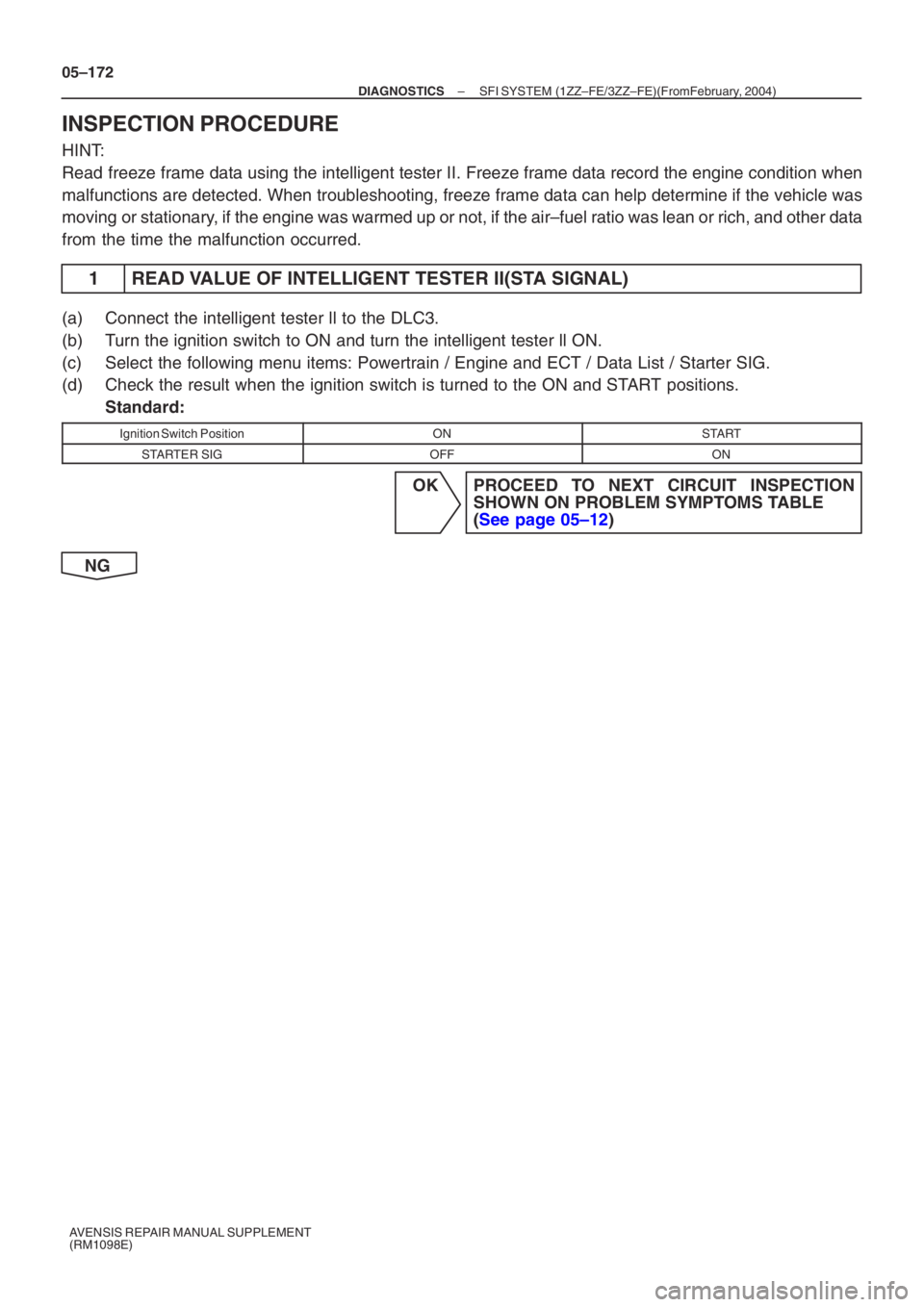
1 READ VALUE OF INTELLIGENT TESTER II(STA SIGNAL)
(a) Connect the intelligent tester ll to the DLC3.
(b) Turn the ignition switch to ON and turn the intelligent tester ll ON.
(c) Select the following menu items: Powertrain / Engine and ECT / Data List\
/ Starter SIG.
(d) Check the result when the ignition switch is turned to the ON and START positions. Standard:
Ignition Switch PositionONSTART
STARTER SIGOFFON
OK PROCEED TO NEXT CIRCUIT INSPECTION SHOWN ON PROBLEM SYMPTOMS TABLE
(See page 05–12 )
NG