Page 2 of 5135

010B2±13
N17080
Filler Cap
Float
Reservoir Tank
� Grommet
Clip
Slotted Spring Pin
: Specified torque
� Non±reusable partCylinder
Piston
Push Rod
Washer
Snap Ring
Boot
� Gasket
Lock Nut
Clevis Pin
Clevis
N´m (kgf´cm, ft´lbf)
12 (120, 9)
15 (155, 11)
± INTRODUCTIONHOW TO USE THIS MANUAL
01±1
AVENSIS REPAIR MANUAL (RM1018E)
HOW TO USE THIS MANUAL
GENERAL INFORMATION
1. GENERAL DESCRIPTION
(a) This manual is made in accordance with SAE J2008.
(b) Generally, repair operations can be separated in the following 3 main processes:
1. Diagnosis
2. Removing/Installing, Replacing, Disassembling/Reassembling, Checking and Adjusting
3. Final Inspection
(c) This manual explains the 1st process of ºDiagnosisº (found in the ºDiagnosticsº section), the 2nd
pro-
cess of ºRemoving and Installing, Replacing, Disassembling, Installing and Checking, and Adjustingº,
but the 3rd process of ºFinal Inspectionº is omitted.
(d) The following essential operations are not written in this manual. However, these operations must be
performed in actual situations.
(1) Operations with a jack or lift
(2) Cleaning of a removed part when necessary
(3) Visual check
2. INDEX
(a) An alphabetical INDEX section is provided at the end of the book as a reference to help you find the
item to be repaired.
3. PREPARATION
(a) Use of special service tools (SST) and special service materials (SSM) may be required, depending
on the repair situation. Be sure to use SST and SSM when they are required and follow the working
procedure properly. A list of SST and SSM is in the Preparation section of this manual.
4. REPAIR PROCEDURES
(a) Component drawing is placed under the title where necessary.
(b) Non±reusable parts, grease application area, precoated parts and tightening torque are specified in
the component drawings.
Example:
Page 3 of 5135

Illustration:
what to do and where
Component part No. Detailed text: how to perform task
Task heading: what to do
Set part No
D31009
01±2
± INTRODUCTIONHOW TO USE THIS MANUAL
AVENSIS REPAIR MANUAL (RM1018E)
(c) Tightening torque, grease application area, and non±reusable parts are described as important points
in the procedures.
NOTICE:
There are cases where such information can only be explained by using an illustration. In these
cases, all the information such as torque, oil, etc. are described in the illustration.
(d) Installing procedures are performed in the reverse order of the removal and only the important points
are described.
(e) Only items with points are described in the procedure, and the operational portion and content are
placed using an illustration. In the explanations, details of the operational method, standard value and
notices are placed.
(f) There may be a case where the illustrations of similar models are used. In that case, specific details
may be different from the actual vehicle.
(g) The procedures are presented in a step±by±step format:
(1) The illustration shows what to do and where to do it.
(2) The task heading tells what to do.
(3) The explanation text tells how to perform the task and gives other information such as specifica-
tions and warnings.
Example:
HINT:
This format provides an experienced technician with a FAST TRACK to the necessary information. The task
heading can be read at a glance when necessary and the text below provides detailed information. Important
specifications and warnings always are written in bold type to stand out from the rest of the text.
5. SERVICE SPECIFICATIONS
(a) Specifications are presented in bold type throughout the manual. You never have to leave the proce-
dure to look up your specifications. The specifications are also found in the Service Specifications sec-
tion for quick reference.
6. TERMS DEFINITION
CAUTIONIndicates the possibility of injury to you or other people.
NOTICEIndicates the possibility of damage to the components being repaired.
HINTProvides additional information to help you to perform the repair efficiently.
Page 35 of 5135

Z11554
Seal Lock Adhesive
BE1367
Medium Current Fuse and High Current
Fuse Equal Amperage Rating
������
V35002
IllustrationSymbol Part Name Abbreviation
FUSE
MEDIUM CURRENT FUSE
HIGH CURRENT FUSE FUSE
M±FUSE H±FUSE
01±6
±
INTRODUCTION REPAIR INSTRUCTION
AVENSIS REPAIR MANUAL (RM1018E)
(b) JACKING UP AND SUPPORTING VEHICLE (1) Care must be taken when jacking up and supporting the vehicle. Be sure to li\
ft and support thevehicle at the proper locations (See page 01±19).
(c) PRECOATED PARTS(1) Precoated parts such as bolts, nuts, etc., are
coated with a seal lock adhesive at the factory.
(2) If a precoated part is retightened, loosened or caused to move in any way, it must be recoated with
the specified adhesive.
(3) When reusing precoated parts, clean off the old
adhesive and dry the part with compressed air.
Then apply the specified seal lock adhesive to the
bolt, nut or threads.
NOTICE:
Check the torque with the lower limit value of the torque tol-
erance.
(4) Depending on the seal lock agent to be applied,there may be cases where it is necessary to leave
it for a specified time until it hardens.
(d) GASKETS (1) When necessary, use a sealer on gaskets to prevent leaks.
(e) BOLTS, NUTS AND SCREWS (1) Carefully follow all the specifications for tightening torques. Always u\
se a torque wrench.
(f) FUSES(1) When replacing fuses, be sure that a new fuse hasthe correct amperage rating. DO NOT exceed the
rating, or use one with a lower rating.
Page 2496 of 5135
G23865
±
REAR SUSPENSION REAR SHOCK ABSORBER WITH COIL SPRING
27±13
AVENSIS REPAIR MANUAL (RM1018E)
24. FULLY TIGHTEN REAR SHOCK ABSORBER WITH
COIL SPRING
(a) Fully tighten the bolt and nut.
Torque: 160 N �m (1,632 kgf �cm, 118 ft �lbf)
NOTICE:
�When installing the bolt, hold the nut not to rotate.
�Be sure to empty the vehicle when fully tightening the
bolt and nut.
25.INSPECT AND ADJUST REAR WHEEL ALIGNMENT (See page 27±4)
26. CHECK ABS SPEED SENSOR SIGNAL
(a)ABD WITH EBD SYSTEM (See page 05±699)
(b)ABD WITH EBD & BA & TRC & VSC SYSTEM ( See page 05±756)
Page 2527 of 5135
30092±02
D27405SST
Hold
Turn
D27401
Hold
Turn
Nut
Washer
±
DRIVE SHAFT / PROPELLER SHAFT FRONT AXLE LH HUB BOLT
30±29
AVENSIS REPAIR MANUAL (RM1018E)
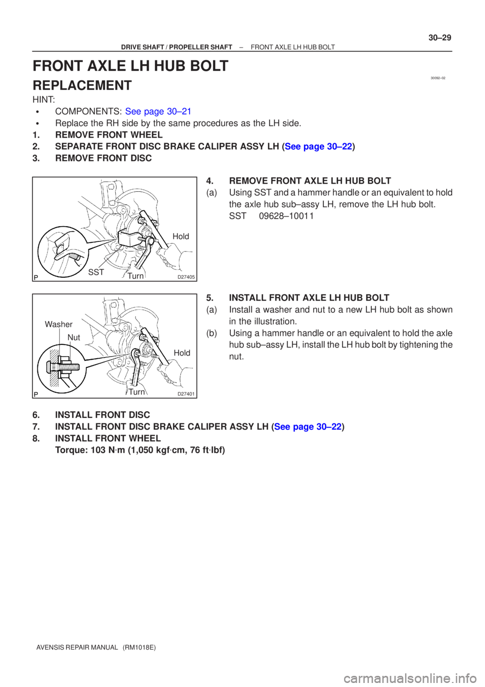
FRONT AXLE LH HUB BOLT
REPLACEMENT
HINT:
�COMPONENTS: See page 30±21
�Replace the RH side by the same procedures as the LH side.
1. REMOVE FRONT WHEEL
2.SEPARATE FRONT DISC BRAKE CALIPER ASSY LH (See page 30±22)
3. REMOVE FRONT DISC
4. REMOVE FRONT AXLE LH HUB BOLT
(a) Using SST and a hammer handle or an equivalent to holdthe axle hub sub±assy LH, remove the LH hub bolt.
SST 09628±10011
5. INSTALL FRONT AXLE LH HUB BOLT
(a) Install a washer and nut to a new LH hub bolt as shown in the illustration.
(b) Using a hammer handle or an equivalent to hold the axle hub sub±assy LH, install the LH hub bolt by tightening the
nut.
6. INSTALL FRONT DISC
7.INSTALL FRONT DISC BRAKE CALIPER ASSY LH (See page 30±22)
8. INSTALL FRONT WHEEL Torque: 103 N �m (1,050 kgf �cm, 76 ft �lbf)
Page 2561 of 5135
G21542
G21542
G23879
Matchmarks
27±28
±
REAR SUSPENSION UPPER CONTROL ARM ASSY
AVENSIS REPAIR MANUAL (RM1018E)
(b) Install the upper control arm assy, and temporarily tighten the bolt and nut.
4. INSTALL REAR WHEEL Torque: 103 N �m (1,050 kgf �cm, 76 ft �lbf)
5.STABILIZE SUSPENSION (See page 27±8)
6. FULLY TIGHTEN UPPER CONTROL ARM ASSY
NOTICE:
Be sure to empty the vehicle when fully tightening the bolt
and nut.
(a) Fully tighten the bolt and nut.Torque: 74 N �m (755 kgf �cm, 55 ft �lbf)
NOTICE:
When instaling the bolt, hold the nut not to rotate.
(b) Align the matchmarks, and fully tighten the nut. Torque: 74 N �m (755 kgf �cm, 55 ft �lbf)
7.INSPECT AND ADJUST REAR WHEEL ALIGNMENT (See page 27±4)
Page 2563 of 5135

(e) Using SST, remove the lower control arm assy LH from
the rear axle")
������G23882
SST
G22395
G23871
������G25777
±
REAR SUSPENSION LOWER CONTROL ARM ASSY LH
27±25
AVENSIS REPAIR MANUAL (RM1018E)
(e) Using SST, remove the lower control arm assy LH from
the rear axle carrier sub±assy LH.
SST 09610±20012
NOTICE:
Do not damage the dust cover.
3. INSPECT LOWER CONTROL ARM ASSY LH
(a) Before installing the nut, flip the ball joint stud back and forth 5 times as shown in the illustration.
(b) Using a torque wrench, continuously turn the nut for 2 to 4 seconds per 1 turn, and take the torque reading at the
5th turn.
Turning torque:
3.0 N�m (31 kgf �cm, 27 in. �lbf) or less
NOTICE:
�Neither unusual drag nor rattle occurs during the
rotation.
�Neither crack nor grease leakage exists on the dust
cover.
�Make sure that lower control arm assy LH is not de-
formed.
4. INSTALL LOWER CONTROL ARM ASSY LH
(a) Install the member side lower control arm assy LH, and temporarily tighten bolt.
(b) Install the nut. Torque: 60 N �m (612 kgf �cm, 44 ft �lbf)
(c) Install the clip.
NOTICE:
�When the holes for the clip are not aligned, adjust
them by tightening the nut. The tightening angle for
the adjustment must be less than 60 �.
�Insert the clip from the rear side of a vehicle.
5. INSTALL REAR WHEEL Torque: 103 N �m (1,050 kgf �cm, 76 ft �lbf)
6.STABILIZE SUSPENSION (See page 27±8)
Page 2572 of 5135
G23875
G23874
G23865
G23880
27±22
± REAR SUSPENSIONREAR SUSPENSION ARM ASSY NO.1 LH
AVENSIS REPAIR MANUAL (RM1018E)
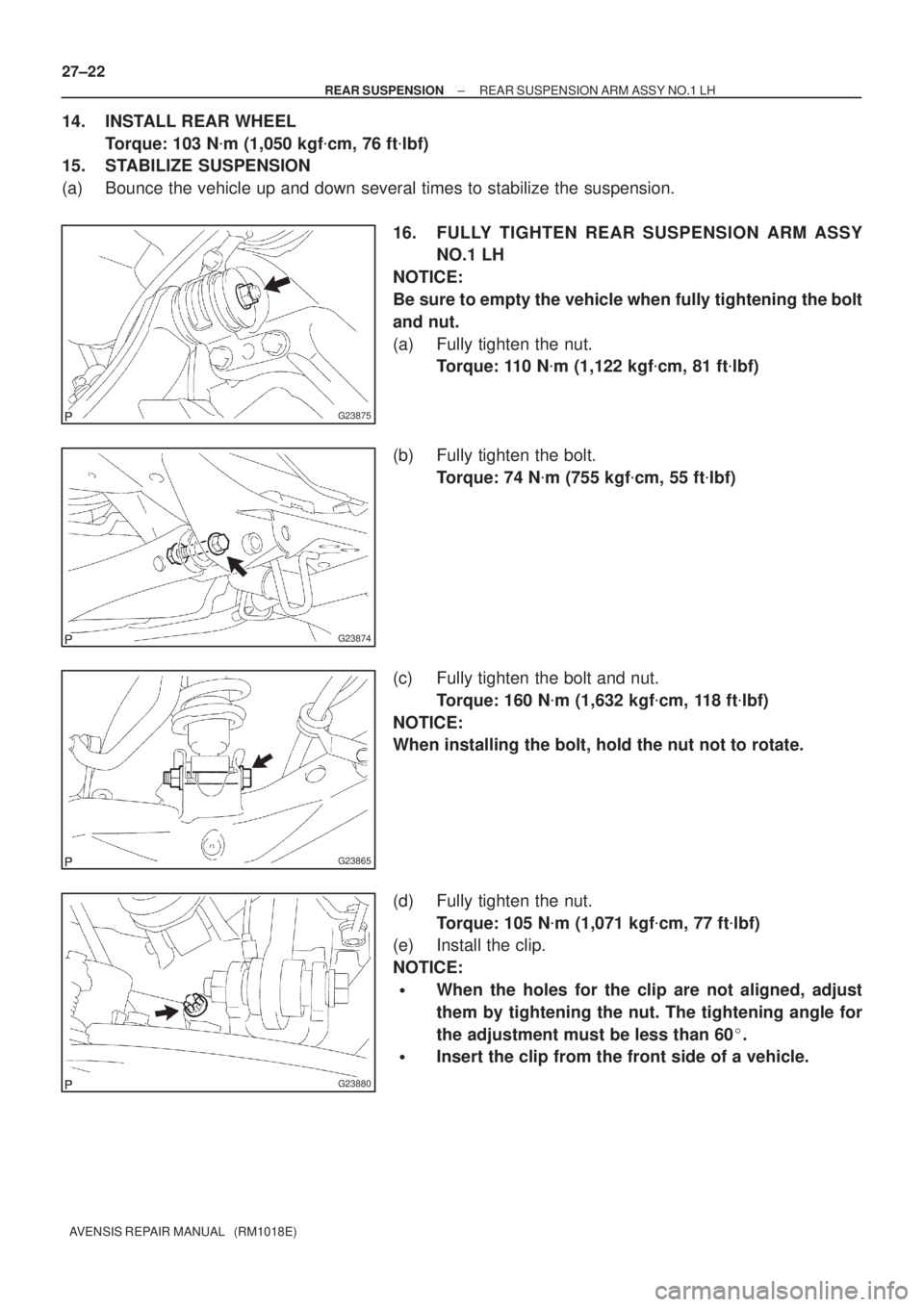
14. INSTALL REAR WHEEL
Torque: 103 N�m (1,050 kgf�cm, 76 ft�lbf)
15. STABILIZE SUSPENSION
(a) Bounce the vehicle up and down several times to stabilize the suspension.
16. FULLY TIGHTEN REAR SUSPENSION ARM ASSY
NO.1 LH
NOTICE:
Be sure to empty the vehicle when fully tightening the bolt
and nut.
(a) Fully tighten the nut.
Torque: 110 N�m (1,122 kgf�cm, 81 ft�lbf)
(b) Fully tighten the bolt.
Torque: 74 N�m (755 kgf�cm, 55 ft�lbf)
(c) Fully tighten the bolt and nut.
Torque: 160 N�m (1,632 kgf�cm, 118 ft�lbf)
NOTICE:
When installing the bolt, hold the nut not to rotate.
(d) Fully tighten the nut.
Torque: 105 N�m (1,071 kgf�cm, 77 ft�lbf)
(e) Install the clip.
NOTICE:
�When the holes for the clip are not aligned, adjust
them by tightening the nut. The tightening angle for
the adjustment must be less than 60�.
�Insert the clip from the front side of a vehicle.

24. FULLY TIGHTEN REAR SHOCK ABSORBER WITH
COIL SPRING
(a) Fully tighten the bolt and nut.
Torqu")

(b) Install the upper control arm assy, and temporarily tighten the bolt and nut.
4.")