Page 2573 of 5135
G23881
������G25777
G23871
±
REAR SUSPENSION REAR SUSPENSION ARM ASSY NO.1 LH
27±23
AVENSIS REPAIR MANUAL (RM1018E)
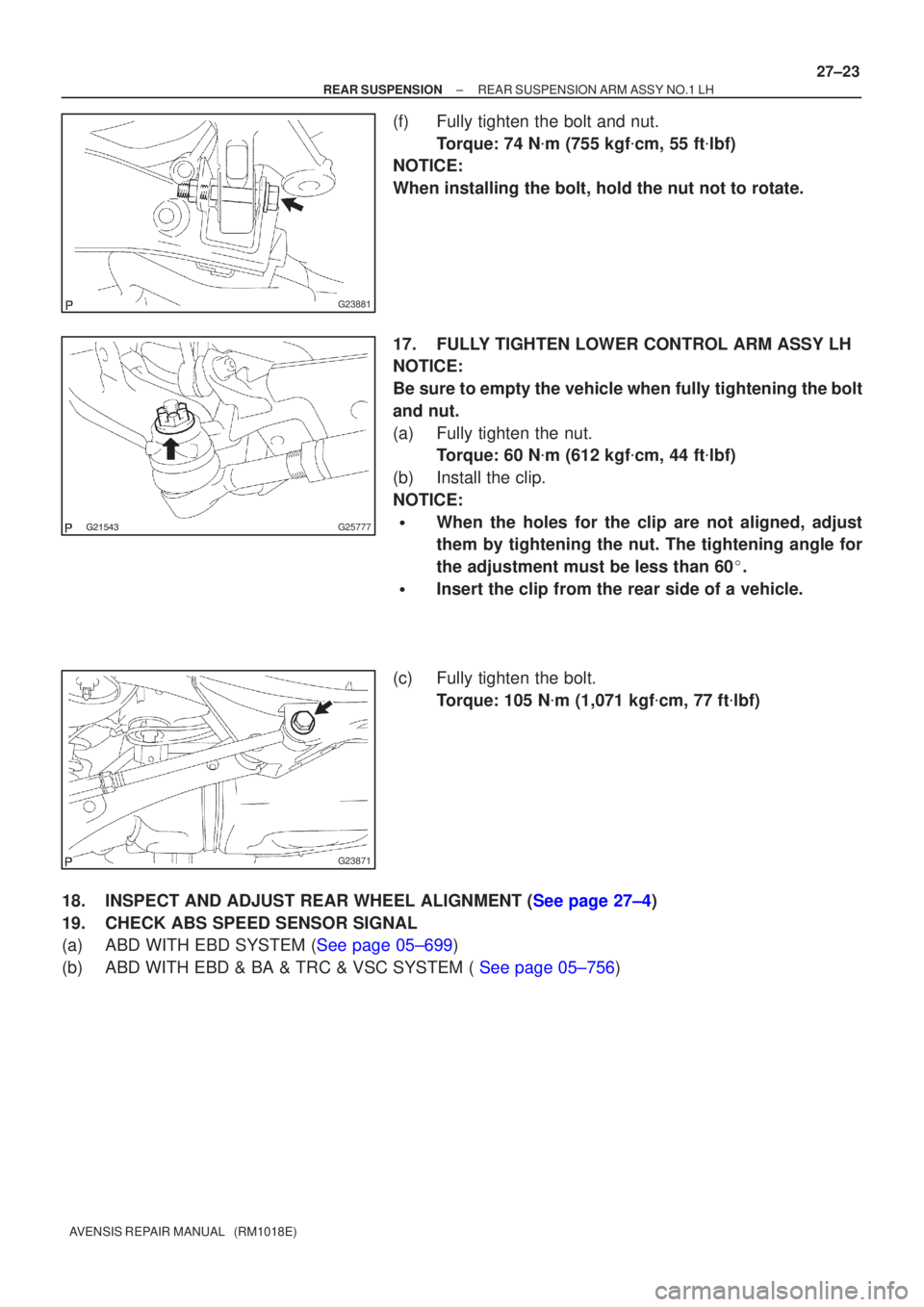
(f) Fully tighten the bolt and nut.
Torque: 74 N �m (755 kgf �cm, 55 ft �lbf)
NOTICE:
When installing the bolt, hold the nut not to rotate.
17. FULLY TIGHTEN LOWER CONTROL ARM ASSY LH
NOTICE:
Be sure to empty the vehicle when fully tightening the bolt
and nut.
(a) Fully tighten the nut. Torque: 60 N �m (612 kgf �cm, 44 ft �lbf)
(b) Install the clip.
NOTICE:
�When the holes for the clip are not aligned, adjust
them by tightening the nut. The tightening angle for
the adjustment must be less than 60 �.
�Insert the clip from the rear side of a vehicle.
(c) Fully tighten the bolt. Torque: 105 N �m (1,071 kgf �cm, 77 ft �lbf)
18.INSPECT AND ADJUST REAR WHEEL ALIGNMENT (See page 27±4)
19. CHECK ABS SPEED SENSOR SIGNAL
(a)ABD WITH EBD SYSTEM (See page 05±699)
(b)ABD WITH EBD & BA & TRC & VSC SYSTEM ( See page 05±756)
Page 2848 of 5135

38. INSTALL TIE ROD END SUB±ASSY LH
(a) Screw the lock nut")
F41467
Matchmarks
D30594
D30593
Matchmarks
51±42
±
POWER STEERING RACK & PINION POWER STEERING GEAR ASSY
AVENSIS REPAIR MANUAL (RM1018E)
38. INSTALL TIE ROD END SUB±ASSY LH
(a) Screw the lock nut and the tie rod end sub±assy to the rack end until the matchmarks are aligned.
Torque: 74 N �m (750 kgf �cm, 54 ft �lbf)
HINT:
After adjusting toe±in, torque the lock nut
(See page 26±6).
39. INSTALL TIE ROD END SUB±ASSY RH
HINT:
Perform the same procedure on the other side. 40. INSTALL RACK & PINION POWER STEERING GEARASSY
(a) Install the power steering gear assy with the 4 bolts and the nuts.
Torque: 49 N �m (500 kgf �cm, 36 ft �lbf)
NOTICE:
�The 4 bushings must be securely installed to the pow-
er steering gear assy.
�When tightening the bolts for power steering gear, the
bushings should not be bitten in.
�Because the nut has its own stopper, do not turn the
nut and torque the bolt with the nut fixed.
41. INSTALL STEERING INTERMEDIATE SHAFT
(a) Align the matchmarks on the intermediate shaft with the pinion shaft.
(b) Install the bolt.
Torque: 35 N �m (360 kgf �cm, 26 ft �lbf)
42. INSTALL STEERING COLUMN HOLE COVER SUB±ASSY NO.1
Page 4879 of 5135
D03916
SST
Counter Drive
GearTransaxle
Case
2nd Brake Hub
w/ Front Planetary
Gear Assy
SST
D03917
D03596
SST
− AUTOMATIC TRANSMISSION / TRANSAUTOMATIC TRANSAXLE ASSY (U151E/U151F)
40−49
U151E, U151F A/T REPAIR MANUAL (RM1021U)
(b) Using SST and a press, press−fit the front planetary gear
assy.
SST 09950−60010 (09951−00500), 09950−70010
(09951−07100)
NOTICE:
SDo not apply excessive pressure to it.
SPress the inner race of LH tapered roller bearing,
counter gear and front planetary gear assembly to the
position where no pre−load should be applied to one
pair of tapered roller bearings (left and right).
(c) Install the new washer, as shown in the illustration.
(d) Using SST, install the nut.
SST 09387−00030, 09387−00080
Torque: 210−350 N�m
(2,141kgf�cm,155 ft�lbf−3,569 kgf�cm, 258 ft�lbf)
NOTICE:
Assemble the washer after pressing each part, then tighten
the nut to minimum tightening torque.

40−49
U151E, U15")