Page 39 of 5135

(3)Even in the case of a minor collision where the SRS does not deploy, the horn button assembly, instrument pan")
D30401
Mark
01±10
±
INTRODUCTION REPAIR INSTRUCTION
AVENSIS REPAIR MANUAL (RM1018E)
(3)Even in the case of a minor collision where the SRS does not deploy, the horn button assembly, instrument panel passenger airbag assembly and seat belt pretensioner should be in\
spected
(See pages 60±19, 60±19 and 61±9).
(4)Never use the SRS related parts from another vehicle. When replacing the part\
s, replace them with new parts.
(5)Before repairs, remove the airbag sensor if there is a possibility of sh\
ock during repairs.
(6)Never disassemble and repair the center airbag sensor assembly, side airbag sensor assembly, horn button assembly, instrument panel passenger airbag assembly, front seat airbag assembly,
curtain shield airbag assembly or seat belt pretensioner.
(7)If the center airbag sensor assembly, the side airbag sensor assembly, the horn button assembly, the instrument panel passenger airbag assembly have been dropped, or if the\
re are cracks,
dents or other defects in the case, bracket or connector, replace them with new ones.
(8)Do not directly expose the airbag sensor assembly, the side airbag sensor assembly, the horn button assembly, the instrument panel passenger airbag assembly or the seat belt pretensioner
to hot air or flames.
(9)Use a volt/ohmmeter with high impedance (10 k �/V minimum) for troubleshooting electrical cir-
cuits.
(10)Information labels are attached to the SRS components. Follow the instru\
ctions on the notices.
(11)After work on the supplemental restraint system is completed, check the SRS w\
arning light (See page 05±1184)
(b)SPIRAL CABLE (in Combination Switch)(1)The steering wheel must be fitted correctly to thesteering column with the spiral cable at the neutral
position, otherwise cable disconnection and other
troubles may occur. Refer to page 60±26 of this
manual concerning the correct installation of the
steering wheel.
(c) HORN BUTTON ASSEMBLY (with Airbag) (1) When removing the horn button assembly or handling a new horn button, it sho\
uld be placed withthe top of the pad surface facing upward. Placing it with the pad surface facing downward may
lead to a serious accident if the airbag deploys for some reasons. Also, do \
not place anything
on top of the horn button.
(2) Never measure the resistance of the airbag squib (This may cause the airbag to inflate, which is very dangerous).
(3) Grease should not be applied to the horn button assembly, and the pad should not be cleaned with any type of detergent.
(4) Store the horn button assembly where the ambient temperature remains below 93 �C (200 �F),
without high humidity and away from electrical noise.
(5) When using electric welding, disconnect the airbag connector (4 yellow pins\
) under the steering column near the combination switch connector before starting work.
Page 40 of 5135

(6)When disposing the vehicle or the horn button a")
D25096
Example:CORRECTWRONG
Z13950
Example:
D27522
Example: CORRECT WRONG
±
INTRODUCTION REPAIR INSTRUCTION
01±11
AVENSIS REPAIR MANUAL (RM1018E)
(6)When disposing the vehicle or the horn button assembly alone, the airbag\
should be inflated us-
ing an SST before disposal (See page 60±19).
Perform the operation in a safe place away from electrical noise.
(d)INSTRUMENT PANEL PASSENGER AIRBAG ASSEMBLY (1)Always place a removed or new instrument panel passenger airbag assembly\
with the airbaginflation direction facing upward. Placing the airbag assembly with the airbag inflation direction
facing downward could cause a serious accident if the airbag deploys.
(2)Never measure the resistance of the airbag squib (This may cause the airbag to inflate, which is very dangerous).
(3)Grease should not be applied to the instrument panel passenger airbag assembly\
and the airbag door should not be cleaned with detergents of any kind.
(4)Store the airbag assembly where the ambient temperature remains below 93 �C (200 �F), without
high humidity and away from electrical noise.
(5)When using electric welding, disconnect the airbag connector (4 yellow pins\
) installed on the as- sembly before starting work.
(6)When disposing of a vehicle or the airbag assembly unit, the airbag should be deployed using\
SST before disposal (See page 60±30).
Activate in a safe place away from electrical noise.
Page 86 of 5135
022L2±01
02±56
± PREPARATIONCOMMUNICATION SYSTEM
AVENSIS REPAIR MANUAL (RM1018E)
COMMUNICATION SYSTEM
PREPARATION
Recomended Tools
09082±00050TOYOTA Electrical Tester SetHORN SYSTEM
Page 89 of 5135

SUPPLEMENTAL RESTRAINT SYSTEM
PREPARATION
SST
09082±00700SRS Airbag Deployment ToolHORN BUTTON ASSY
CURT")
022L5±01
02±52
± PREPARATIONSUPPLEMENTAL RESTRAINT SYSTEM
AVENSIS REPAIR MANUAL (RM1018E)
SUPPLEMENTAL RESTRAINT SYSTEM
PREPARATION
SST
09082±00700SRS Airbag Deployment ToolHORN BUTTON ASSY
CURTAIN SHIELD AIR BAG ASSY LH
FRONT SEAT AIRBAG ASSY LH
INSTRUMENT PANEL PASSENGER
AIR BAG ASSY
INSTRUMENT PANEL AIR BAG
ASSY
09082±00750Airbag Deployment Wire
Sub±harness No.3FRONT SEAT AIRBAG ASSY LH
09082±00780Airbag Deployment Wire
Sub±harness No.6HORN BUTTON ASSY
INSTRUMENT PANEL PASSENGER
AIR BAG ASSY
09082±00802Airbag Deployment Wire
Sub±Harness No. 8HORN BUTTON ASSY
CURTAIN SHIELD AIR BAG ASSY LH
INSTRUMENT PANEL AIR BAG
ASSY
(09082±10801)Wire AHORN BUTTON ASSY
CURTAIN SHIELD AIR BAG ASSY LH
INSTRUMENT PANEL AIR BAG
ASSY
(09082±20801)Wire BCURTAIN SHIELD AIR BAG ASSY LH
INSTRUMENT PANEL AIR BAG
ASSY
(09082±30801)Wire CHORN BUTTON ASSY
09950±50013Puller C SetSPIRAL CABLE SUB±ASSY
(09951±05010)Hanger 150SPIRAL CABLE SUB±ASSY
(09952±05010)Slide ArmSPIRAL CABLE SUB±ASSY
(09953±05020)Center Bolt 150SPIRAL CABLE SUB±ASSY
(09954±05021)Claw No.2SPIRAL CABLE SUB±ASSY
Page 90 of 5135
± PREPARATIONSUPPLEMENTAL RESTRAINT SYSTEM
02±53
AVENSIS REPAIR MANUAL (RM1018E)
Recomended Tools
09042±00010Torx Socket T30HORN BUTTON ASSY
SPIRAL CABLE SUB±ASSY
09070±20010Moulding RemoverAIR BAG SENSOR ASSY CENTER
Equipment
Torque wrench
Bolt Length: 35.0 mm (1.378 in.) Pitch: 1.0 mm (0.039 in.)
Diam.: 6.0 mm (0.236 in.)Airbag disposal
Tire Width: 185 mm (7.28 in.) Inner diam.: 360 mm (14.17 in.)Airbag disposal
Tire with disc wheel Width: 185 mm (7.28 in.)
Inner diam.: 360 mm (14.17 in.)Airbag disposal
Plastic bagAirbag disposal
Page 162 of 5135
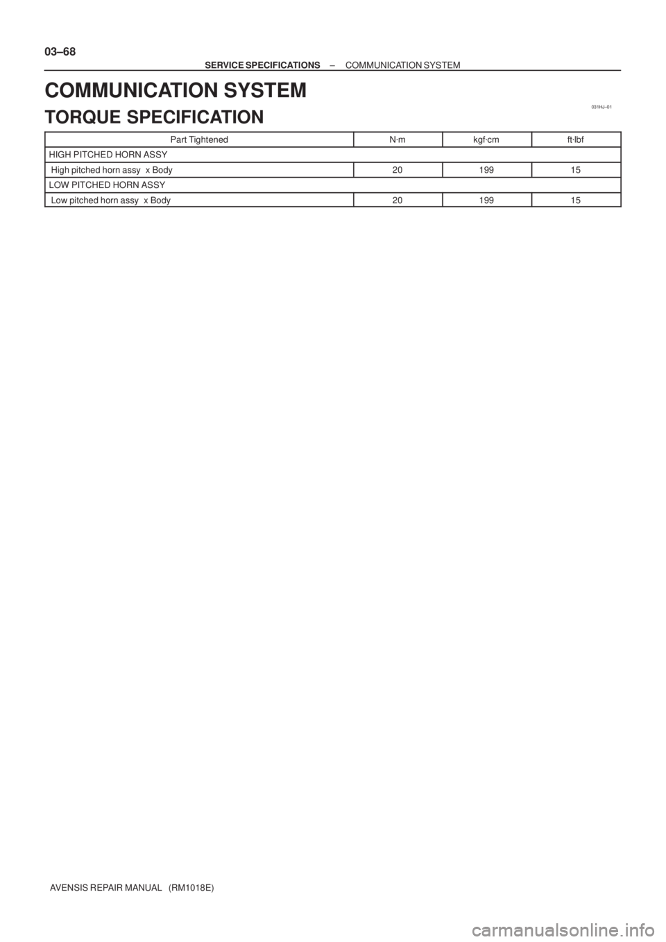
031HJ±01
03±68
± SERVICE SPECIFICATIONSCOMMUNICATION SYSTEM
AVENSIS REPAIR MANUAL (RM1018E)
COMMUNICATION SYSTEM
TORQUE SPECIFICATION
Part TightenedN�mkgf�cmft�lbf
HIGH PITCHED HORN ASSY
High pitched horn assy x Body2019915
LOW PITCHED HORN ASSY
Low pitched horn assy x Body2019915
Page 167 of 5135
031HM±01
± SERVICE SPECIFICATIONSSUPPLEMENTAL RESTRAINT SYSTEM
03±63
AVENSIS REPAIR MANUAL (RM1018E)
SUPPLEMENTAL RESTRAINT SYSTEM
TORQUE SPECIFICATION
Part TightenedN�mkgf�cmft�lbf
Horn button assy x Steering wheel assy8.89078 in.�lbf
Steering wheel assy x Steering column assy5051037
Instrument panel passenger airbag assy x Instrument panel reinforcement2020014
Curtain shield airbag assy x Body3.53631 in.�lbfCurtain shield airbag assy x Body3.5
14
36
143
31 in.lbf
10
Instrument panel airbag assy x Instrument panel reinforcement1818413
Airbag sensor assy center x Body17.517813
Airbag front sensor set bolt7.57666 in.�lbf
Side airbag sensor assy LH x Body17.517813
Airbag sensor rear LH x Body17.517813
Seat position airbag sensor x Front seat8.08271 in.�lbf
Page 1217 of 5135

DTCB0")
������������
��
��
H41439
D SquibAirbag
Sensor
Assy
CenterSpiral
Cable
Sub±assy
Color: Orange
A
B
C
D
E
F
05±1202
±
DIAGNOSTICS SUPPLEMENTAL RESTRAINT SYSTEM
AVENSIS REPAIR MANUAL (RM1018E)
DTCB0101/14OPEN IN D SQUIB CIRCUIT
CIRCUIT DESCRIPTION
The D squib circuit consists of the airbag sensor assy center, the spiral cable sub±assy and the horn button
assy.
This circuit actuates the SRS to deploy when the SRS deployment conditions a\
re fulfilled.
DTC B0101/14 is recorded when an open circuit is detected in the D squib\
circuit.
DTC No.DTC Detecting ConditionTrouble Area
B0101/14
� Open circuit in D+ wire harness or D± wire harness of D
squib
� D squib malfunction
� Spiral cable sub±assy malfunction
� Airbag sensor assy center malfunction�Horn button assy (D squib)
� Spiral cable sub±assy
� Airbag sensor assy center
� Instrument panel wire
WIRING DIAGRAM
See page 05±1198.
INSPECTION PROCEDURE
1 CHECK D SQUIB CIRCUIT(AIRBAG SENSOR ASSY CENTER ± HORN BUTTON
ASSY)
(a) Turn the ignition switch to the LOCK position.
(b) Disconnect the negative (±) terminal cable from the bat-
tery, and wait for at least 90 seconds.
(c) Disconnect the connectors from the airbag sensor assy
center and the horn button assy.
(d) Measure the resistance between D+ and D± of the con- nector ºEº.
OK:
Resistance: Below 1 �
NG Go to step 4
OK
056LY±04

COMMUNICATION SYSTEM
PREPARATION
Recomended Tools
09082±00050TOYOTA Electrical Tester SetHORN SYSTEM")

Recomended Tools
09042±00010Torx Socket T30HORN BUTTON ASSY
SPIRAL CABLE SUB±ASSY
09070±20010Moulding RemoverAIR")