Page 55 of 5135
022KG±01
02±28
± PREPARATIONTIRE & WHEEL
AVENSIS REPAIR MANUAL (RM1018E)
TIRE & WHEEL
PREPARATION
Equipment
Tire pressure gauge
Dial indicator with magnetic base
Wheel balancer
Page 57 of 5135
± PREPARATIONREAR SUSPENSION
02±27
AVENSIS REPAIR MANUAL (RM1018E)
(09955±04051)Claw No.5REAR SUSPENSION ARM ASSY
NO.1 LH
(09957±04010)AttachmentREAR SUSPENSION ARM ASSY
NO.1 LH
(09958±04011)HolderREAR SUSPENSION ARM ASSY
NO.1 LH
Recomended Tools
09040±00011Hexagon Wrench SetREAR SHOCK ABSORBER WITH
COIL SPRING
REAR SUSPENSION ARM ASSY
NO.1 LH
STABILIZER BAR REAR
(09043±20050)Socket Hexagon Wrench 5REAR SHOCK ABSORBER WITH
COIL SPRING
REAR SUSPENSION ARM ASSY
NO.1 LH
STABILIZER BAR REAR
(09043±20060)Socket Hexagon Wrench 6REAR SHOCK ABSORBER WITH
COIL SPRING
Equipment
Torque wrench
Dial indicator with magnetic base
Wheel balancer
Tire pressure gauge
Alignment tester
Toe±in gauge
Camber±caster±kingpin gauge
Drill
Page 58 of 5135

022KF±01
± PREPARATIONFRONT SUSPENSION
02±25
AVENSIS REPAIR MANUAL (RM1018E)
FRONT SUSPENSION
PREPARATION
SST
09628±62011Boll Joint PullerLOWER BALL JOINT ASSY FRONT
LH
STABILIZER BAR FRONT
FRONT SUSPENSION ARM
SUB±ASSY LOWER NO.1 LH(ATM)
09727±30021Coil Spring CompressorFRONT SHOCK ABSORBER WITH
COIL SPRING
09729±22031Front Spring Upper Seat HolderFRONT SHOCK ABSORBER WITH
COIL SPRING
09930±00010Drive Shaft Nut ChiselLOWER BALL JOINT ASSY FRONT
LH
Recomended Tools
09011±12301Socket Wrench 30 mmLOWER BALL JOINT ASSY FRONT
LH
09040±00011Hexagon Wrench SetFRONT SHOCK ABSORBER WITH
COIL SPRING
STABILIZER BAR FRONT
FRONT SUSPENSION ARM
SUB±ASSY LOWER NO.1 LH(ATM)
FRONT SUSPENSION ARM
SUB±ASSY LOWER NO.1 LH(MTM)
(09043±20060)Socket Hexagon Wrench 6FRONT SHOCK ABSORBER WITH
COIL SPRING
STABILIZER BAR FRONT
FRONT SUSPENSION ARM
SUB±ASSY LOWER NO.1 LH(ATM)
FRONT SUSPENSION ARM
SUB±ASSY LOWER NO.1 LH(MTM)
Equipment
Torque wrench
Dial indicator with magnetic base
Tire pressure gauge
Alignment tester
Toe±in gauge
Angle gauge
Camber±caster±kingpin gauge
Engine Sling Device
Drill
Page 75 of 5135

02±16
± PREPARATIONENGINE MECHANICAL
AVENSIS REPAIR MANUAL (RM1018E) Vernier calipers
Tire pressure gauge
Alignment tester
Toe±in gauge
OBD II scan tool
Deep socket wrench 24 mm
Slide calipers
Sand paper (#400)
Wooden block
Chain block
Spark plug cleaner
Angle gauge
Universal engine lifter
SSM
08826±00080Seal Packing Black or equivalent
(FIPG)VALVE CLEARANCE(1AZ±FE)
CYLINDER HEAD GASKET(1AZ±FE)
VALVE CLEARANCE(1AZ±FSE)
CYLINDER HEAD
GASKET(1AZ±FSE)
VALVE CLEARANCE(1CD±FTV)
TIMING BELT(1CD±FTV)
CAMSHAFT(1CD±FTV)
CYLINDER HEAD
GASKET(1CD±FTV)
CRANKSHAFT SEAL(1CD±FTV)
PARTIAL ENGINE ASSY(1CD±FTV)
VA LV E
CLEARANCE(1ZZ±FE/3ZZ±FE)
CHAIN
SUB±ASSY(1ZZ±FE/3ZZ±FE)
CAMSHAFT(1ZZ±FE/3ZZ±FE)
CYLINDER HEAD
GASKET(1ZZ±FE/3ZZ±FE)
08833±00070ºAdhesive 1324,º
THREE BOND 1324 or equivalentPARTIAL ENGINE ASSY(1AZ±FE)
ENGINE REAR OIL SEAL(1AZ±FE)
PARTIAL ENGINE ASSY(1AZ±FSE)
ENGINE REAR OIL SEAL(1AZ±FSE)
ENGINE REAR OIL SEAL(1CD±FTV)
PARTIAL ENGINE ASSY(1CD±FTV)
PARTIAL ENGINE
ASSY(1ZZ±FE/3ZZ±FE)
ENGINE REAR OIL
SEAL(1ZZ±FE/3ZZ±FE)
Page 148 of 5135

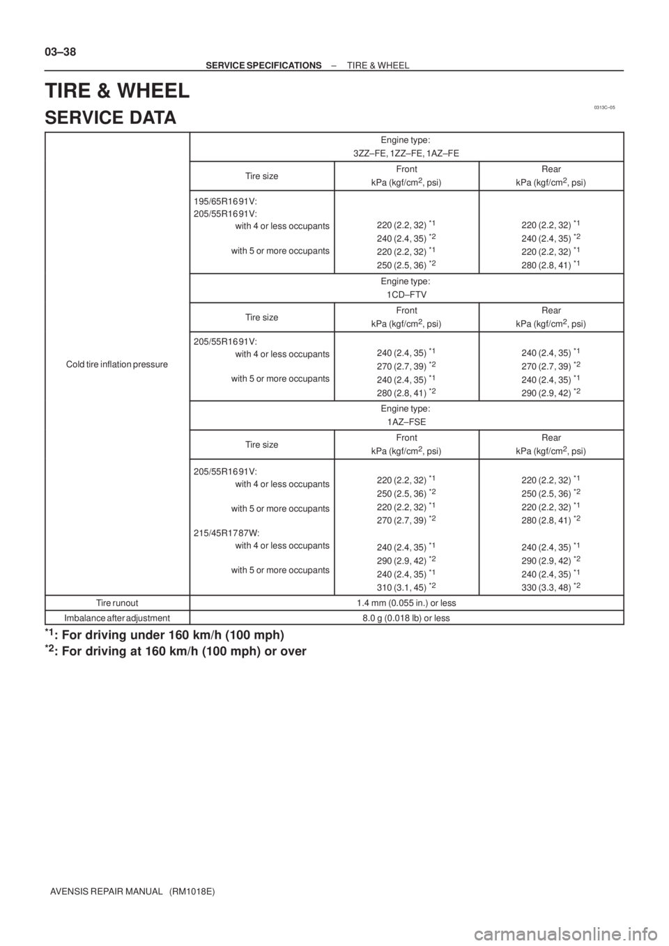
0313C±05
03±38
± SERVICE SPECIFICATIONSTIRE & WHEEL
AVENSIS REPAIR MANUAL (RM1018E)
TIRE & WHEEL
SERVICE DATA
Engine type:
3ZZ±FE, 1ZZ±FE, 1AZ±FE
Tire sizeFront
kPa (kgf/cm2, psi)
Rear
kPa (kgf/cm2, psi)
195/65R16 91V:
205/55R16 91V:
with 4 or less occupants
with 5 or more occupants
220 (2.2, 32) *1
240 (2.4, 35) *2
220 (2.2, 32) *1
250 (2.5, 36) *2
220 (2.2, 32) *1
240 (2.4, 35) *2
220 (2.2, 32) *1
280 (2.8, 41) *1
Engine type:
1CD±FTV
Tire sizeFront
kPa (kgf/cm2, psi)
Rear
kPa (kgf/cm2, psi)
Cold tire inflation pressure
205/55R16 91V:
with 4 or less occupants
with 5 or more occupants
240 (2.4, 35) *1
270 (2.7, 39) *2
240 (2.4, 35) *1
280 (2.8, 41) *2
240 (2.4, 35) *1
270 (2.7, 39) *2
240 (2.4, 35) *1
290 (2.9, 42) *2
Engine type:
1AZ±FSE
Tire sizeFront
kPa (kgf/cm2, psi)
Rear
kPa (kgf/cm2, psi)
205/55R16 91V:
with 4 or less occupants
with 5 or more occupants
215/45R17 87W:
with 4 or less occupants
with 5 or more occupants220 (2.2, 32) *1
250 (2.5, 36) *2
220 (2.2, 32) *1
270 (2.7, 39) *2
240 (2.4, 35) *1
290 (2.9, 42) *2
240 (2.4, 35) *1
310 (3.1, 45) *2
220 (2.2, 32) *1
250 (2.5, 36) *2
220 (2.2, 32) *1
280 (2.8, 41) *2
240 (2.4, 35) *1
290 (2.9, 42) *2
240 (2.4, 35) *1
330 (3.3, 48) *2
Tire runout1.4 mm (0.055 in.) or less
Imbalance after adjustment8.0 g (0.018 lb) or less
*1: For driving under 160 km/h (100 mph)
*2: For driving at 160 km/h (100 mph) or over
Page 2556 of 5135

2801F±02
R03031
������F45650
Front (A)
(B)
± TIRE & WHEELWHEEL AND TIRE SYSTEM
28±1
AVENSIS REPAIR MANUAL (RM1018E)
WHEEL AND TIRE SYSTEM
INSPECTION
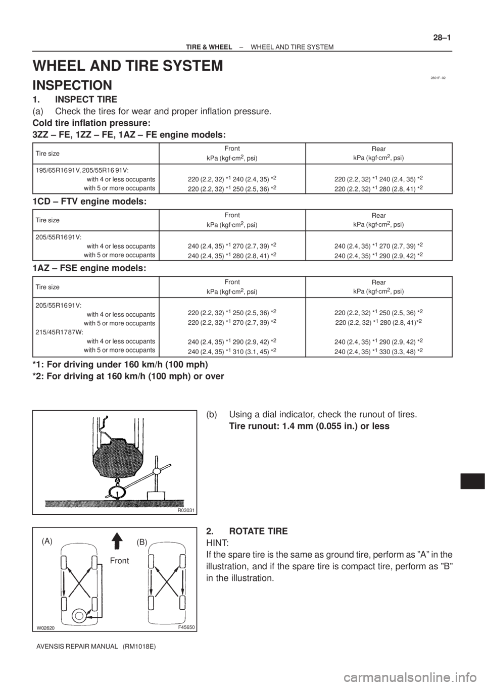
1. INSPECT TIRE
(a) Check the tires for wear and proper inflation pressure.
Cold tire inflation pressure:
3ZZ ± FE, 1ZZ ± FE, 1AZ ± FE engine models:
Tire sizeFront
kPa (kgf�cm2, psi)
Rear
kPa (kgf�cm2, psi)
195/65R16 91V, 205/55R16 91V:
with 4 or less occupants
with 5 or more occupants
220 (2.2, 32) *1 240 (2.4, 35) *2
220 (2.2, 32) *1 250 (2.5, 36) *2220 (2.2, 32) *1 240 (2.4, 35) *2
220 (2.2, 32) *1 280 (2.8, 41) *2
1CD ± FTV engine models:
Tire sizeFront
kPa (kgf�cm2, psi)
Rear
kPa (kgf�cm2, psi)
205/55R16 91V:
with 4 or less occupants
with 5 or more occupants
240 (2.4, 35) *1 270 (2.7, 39) *2
240 (2.4, 35) *1 280 (2.8, 41) *2240 (2.4, 35) *1 270 (2.7, 39) *2
240 (2.4, 35) *1 290 (2.9, 42) *2
1AZ ± FSE engine models:
Tire sizeFront
kPa (kgf�cm2, psi)
Rear
kPa (kgf�cm2, psi)
205/55R16 91V:
with 4 or less occupants
with 5 or more occupants
215/45R17 87W:
with 4 or less occupants
with 5 or more occupants220 (2.2, 32) *1 250 (2.5, 36) *2
220 (2.2, 32) *1 270 (2.7, 39) *2
240 (2.4, 35) *1 290 (2.9, 42) *2
240 (2.4, 35) *1 310 (3.1, 45) *2
220 (2.2, 32) *1 250 (2.5, 36) *2
220 (2.2, 32) *1 280 (2.8, 41)*2
240 (2.4, 35) *1 290 (2.9, 42) *2
240 (2.4, 35) *1 330 (3.3, 48) *2
*1: For driving under 160 km/h (100 mph)
*2: For driving at 160 km/h (100 mph) or over
(b) Using a dial indicator, check the runout of tires.
Tire runout: 1.4 mm (0.055 in.) or less
2. ROTATE TIRE
HINT:
If the spare tire is the same as ground tire, perform as ºAº in the
illustration, and if the spare tire is compact tire, perform as ºBº
in the illustration.
Page 2811 of 5135

F44793Matchmarks
F44789
RHD:
Matchmarks
A
B
F45709
50−16
−
STEERING COLUMN STEERING COLUMN ASSY
(d) Electric Pressure Power Steering
(1) Install the steering sliding yoke with the bolt.
Torque: 35 N �m (360 kgf�cm, 26 ft �lbf)
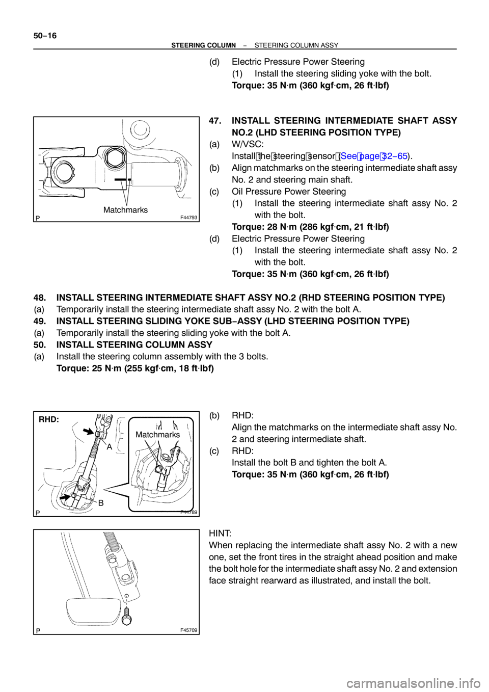
47. INSTALL STEERING INTERMEDIATE SHAFT ASSY NO.2 (LHD STEERING POSITION TYPE)
(a) W/VSC:
Install the steering sensor (See page 32− 65).
(b) Align matchmarks on the steering intermediate shaft assy
No. 2 and steering main shaft.
(c) Oil Pressure Power Steering (1) Install the steering intermediate shaft assy No. 2
with the bolt.
Torque: 28 N �m (286 kgf�cm, 21 ft �lbf)
(d) Electric Pressure Power Steering (1) Install the steering intermediate shaft assy No. 2
with the bolt.
Torque: 35 N �m (360 kgf�cm, 26 ft �lbf)
48. INSTALL STEERING INTERMEDIATE SHAFT ASSY NO.2 (RHD STEERING POSITION TYPE)
(a) Temporarily install the steering intermediate shaft assy No. 2 with the bolt A.
49. INSTALL STEERING SLIDING YOKE SUB −ASSY (LHD STEERING POSITION TYPE)
(a) Temporarily install the steering sliding yoke with the bolt A.
50. INSTALL STEERING COLUMN ASSY
(a) Install the steering column assembly with the 3 bolts.
Torque: 25 N �m (255 kgf�cm, 18 ft �lbf)
(b) RHD: Align the matchmarks on the intermediate shaft assy No.
2 and steering intermediate shaft.
(c) RHD: Install the bolt B and tighten the bolt A.
Torque: 35 N �m (360 kgf�cm, 26 ft �lbf)
HINT:
When replacing the intermediate shaft assy No. 2 with a new
one, set the front tires in the straight ahead position and make
the bolt hole for the intermediate shaft assy No. 2 and extension
face straight rearward as illustrated, and install the bolt.
Page 2820 of 5135

5000D±14
50±2
±
STEERING COLUMN STEERING SYSTEM
AVENSIS REPAIR MANUAL (RM1018E)
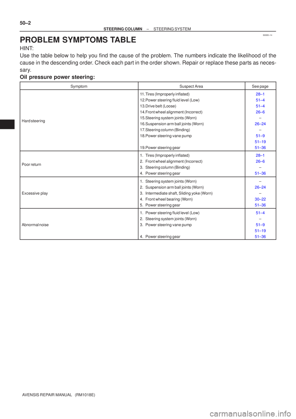
PROBLEM SYMPTOMS TABLE
HINT:
Use the table below to help you find the cause of the problem. The numbers \
indicate the likelihood of the
cause in the descending order. Check each part in the order shown. Repair or replace these parts as n\
eces-
sary.
Oil pressure power steering:
SymptomSuspect AreaSee page
Hard steering
11. Tires (Improperly inflated)
12.Power steering fluid level (Low)
13.Drive belt (Loose)
14.Front wheel alignment (Incorrect)
15.Steering system joints (Worn)
16.Suspension arm ball joints (Worn)
17.Steering column (Binding)
18.Power steering vane pump
19.Power steering gear28±1
51±4
51±4
26±6 ±
26±24 ±
51±9
51±19
51±36
Poor return
1. Tires (Improperly inflated)
2. Front wheel alignment (Incorrect)
3. Steering column (Binding)
4. Power steering gear28±1
26±6 ±
51±36
Excessive play
1. Steering system joints (Worn)
2. Suspension arm ball joints (Worn)
3. Intermediate shaft, Sliding yoke (Worn)
4. Front wheel bearing (Worn)
5. Power steering gear±
26±24 ±
30±22
51±36
Abnormal noise
1. Power steering fluid level (Low)
2. Steering system joints (Worn)
3. Power steering vane pump
4. Power steering gear51±4 ±
51±9
51±19
51±36