Page 13 of 5135

± INTRODUCTIONTERMS
01±39
AVENSIS REPAIR MANUAL (RM1018E)Abbreviations Meaning
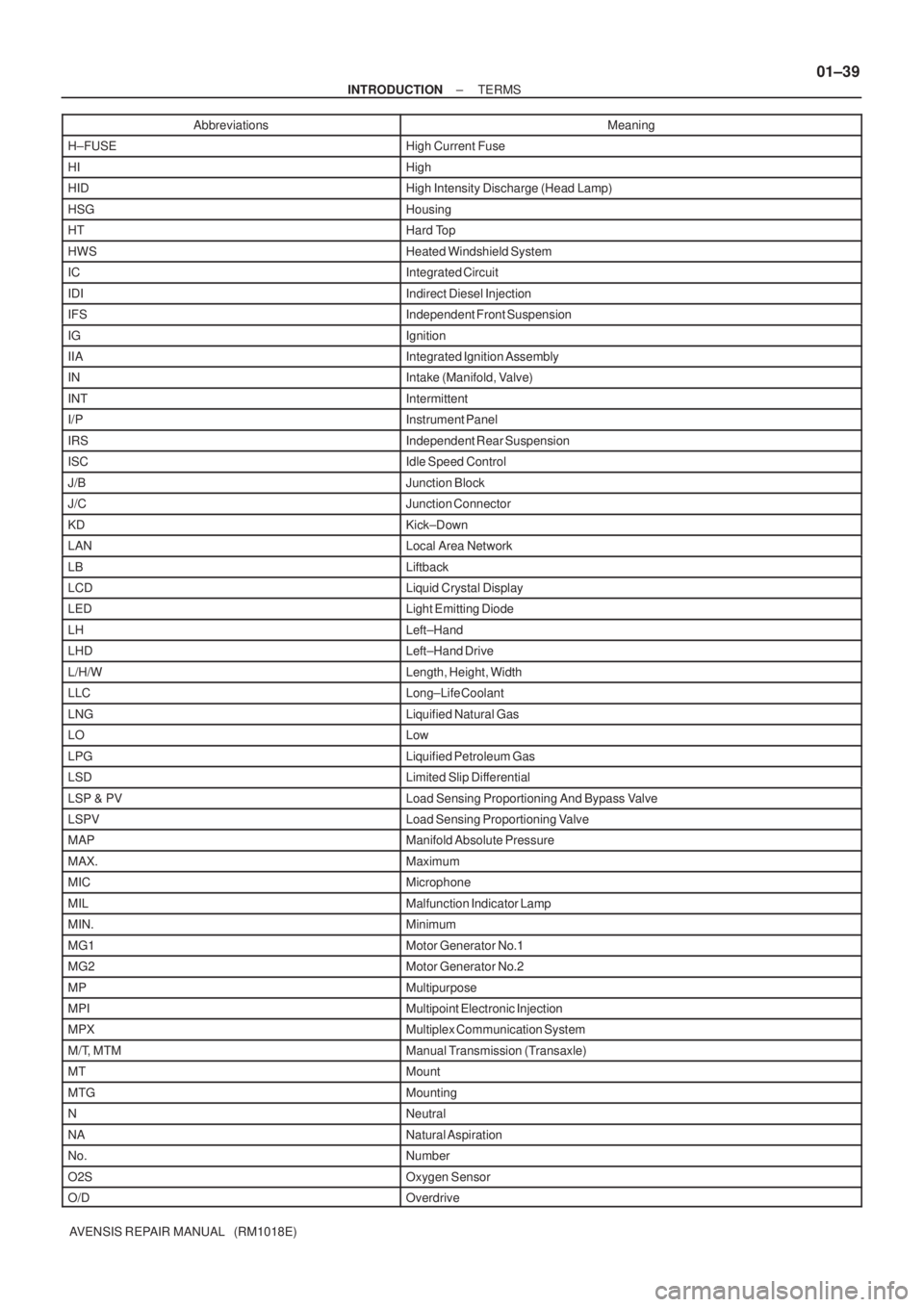
H±FUSEHigh Current Fuse
HIHigh
HIDHigh Intensity Discharge (Head Lamp)
HSGHousing
HTHard Top
HWSHeated Windshield System
ICIntegrated Circuit
IDIIndirect Diesel Injection
IFSIndependent Front Suspension
IGIgnition
IIAIntegrated Ignition Assembly
INIntake (Manifold, Valve)
INTIntermittent
I/PInstrument Panel
IRSIndependent Rear Suspension
ISCIdle Speed Control
J/BJunction Block
J/CJunction Connector
KDKick±Down
LANLocal Area Network
LBLiftback
LCDLiquid Crystal Display
LEDLight Emitting Diode
LHLeft±Hand
LHDLeft±Hand Drive
L/H/WLength, Height, Width
LLCLong±Life Coolant
LNGLiquified Natural Gas
LOLow
LPGLiquified Petroleum Gas
LSDLimited Slip Differential
LSP & PVLoad Sensing Proportioning And Bypass Valve
LSPVLoad Sensing Proportioning Valve
MAPManifold Absolute Pressure
MAX.Maximum
MICMicrophone
MILMalfunction Indicator Lamp
MIN.Minimum
MG1Motor Generator No.1
MG2Motor Generator No.2
MPMultipurpose
MPIMultipoint Electronic Injection
MPXMultiplex Communication System
M/T, MTMManual Transmission (Transaxle)
MTMount
MTGMounting
NNeutral
NANatural Aspiration
No.Number
O2SOxygen Sensor
O/DOverdrive
Page 90 of 5135
± PREPARATIONSUPPLEMENTAL RESTRAINT SYSTEM
02±53
AVENSIS REPAIR MANUAL (RM1018E)
Recomended Tools
09042±00010Torx Socket T30HORN BUTTON ASSY
SPIRAL CABLE SUB±ASSY
09070±20010Moulding RemoverAIR BAG SENSOR ASSY CENTER
Equipment
Torque wrench
Bolt Length: 35.0 mm (1.378 in.) Pitch: 1.0 mm (0.039 in.)
Diam.: 6.0 mm (0.236 in.)Airbag disposal
Tire Width: 185 mm (7.28 in.) Inner diam.: 360 mm (14.17 in.)Airbag disposal
Tire with disc wheel Width: 185 mm (7.28 in.)
Inner diam.: 360 mm (14.17 in.)Airbag disposal
Plastic bagAirbag disposal
Page 175 of 5135

030L1±03
± SERVICE SPECIFICATIONSCLUTCH
03±55
AVENSIS REPAIR MANUAL (RM1018E)
CLUTCH
SERVICE DATA
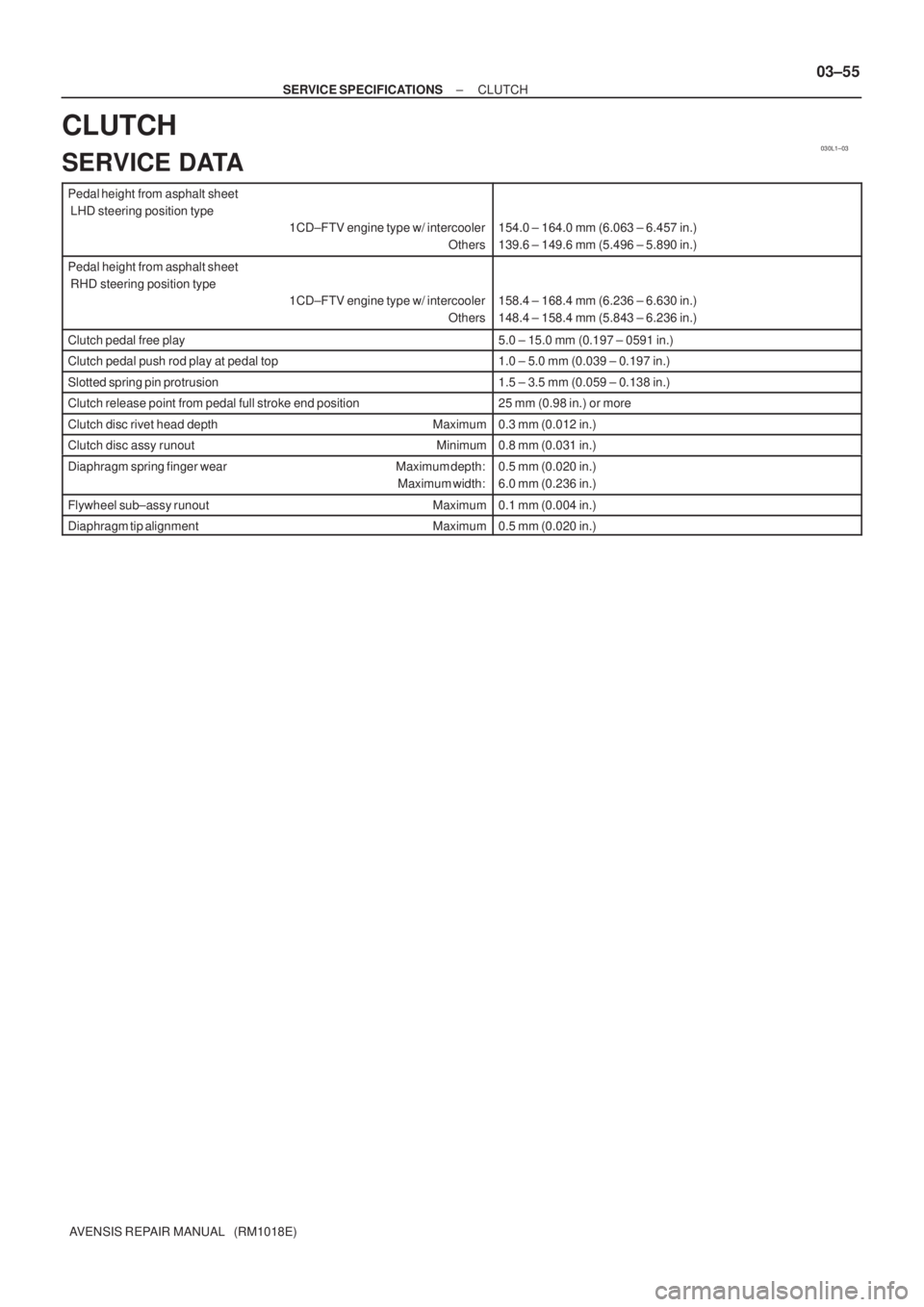
Pedal height from asphalt sheet
LHD steering position type
1CD±FTV engine type w/ intercooler
Others
154.0 ± 164.0 mm (6.063 ± 6.457 in.)
139.6 ± 149.6 mm (5.496 ± 5.890 in.)
Pedal height from asphalt sheet
RHD steering position type
1CD±FTV engine type w/ intercooler
Others
158.4 ± 168.4 mm (6.236 ± 6.630 in.)
148.4 ± 158.4 mm (5.843 ± 6.236 in.)
Clutch pedal free play5.0 ± 15.0 mm (0.197 ± 0591 in.)
Clutch pedal push rod play at pedal top1.0 ± 5.0 mm (0.039 ± 0.197 in.)
Slotted spring pin protrusion1.5 ± 3.5 mm (0.059 ± 0.138 in.)
Clutch release point from pedal full stroke end position25 mm (0.98 in.) or more
Clutch disc rivet head depth Maximum0.3 mm (0.012 in.)
Clutch disc assy runout Minimum0.8 mm (0.031 in.)
Diaphragm spring finger wear Maximum depth:
Maximum width:0.5 mm (0.020 in.)
6.0 mm (0.236 in.)
Flywheel sub±assy runout Maximum0.1 mm (0.004 in.)
Diaphragm tip alignment Maximum0.5 mm (0.020 in.)
Page 324 of 5135

���\b�A79115
Reference (Bank 1 Sensor 2 System Drawing)Heated Oxygen Sensor
EFI Relay
Heater
SensorOX1B HT1BECM
From
Battery EFI Fuse
O1B±
MREL
EFI No.2 Fuse
05±218
±
DIAGNOSTICS SFI SYSTEM(1AZ±FE)
AVENSIS REPAIR MANUAL (RM1018E)
DTCP0141/27OXYGEN SENSOR HEATER CIRCUIT MALFUNCTION (BANK 1 SENSOR 2)
DTCP0161/29OXYGEN SENSOR HEATER CIRCUIT (BANK 2 SENSOR 2)
CIRCUIT DESCRIPTION
Refer to DTC P0136/27 on page 05±211.
HINT:
The ECM provides a pulse width modulated control circuit to adjust current \
through the heater. The heated
oxygen sensor heater circuit uses a relay on the B+ side of the circuit.
DTC No.DTC Detection ConditionTrouble Area
P0141/27
Heated current is 0.2 A or less when heater operates
(1 trip detection logic)�Open or short in heater circuit of heated oxygen sensor
� Heated oxygen sensor heater
P0141/27
P0161/29When heater operates, heated current exceeds 2 A
(1 trip detection logic)
yg
�EFI relay
� ECM
HINT:
�Bank 1 refers to the bank that includes cylinder No.1.
�Bank 2 refers to the bank that does not include cylinder No.1.
�Sensor 1 refers to the sensor closest to the engine assembly.
�Sensor 2 refers to the sensor farthest away from the engine assembly.
WIRING DIAGRAM
Refer to DTC P0136/27 on page 05±211.
INSPECTION PROCEDURE
HINT:
�If different DTCs that are related to a different system are output simultaneously while terminal E2 is
used as a ground terminal, terminal E2 may be open.
�Read freeze frame data using �
\f
���
\f�� �\f��\f�� Freeze frame data records the engine conditions
when a malfunction is detected. When troubleshooting, it is useful for d\
etermining whether the vehicle
was running or stopped, the engine was warmed up or not, the air±fuel ra\
tio was lean or rich, etc. at
the time of the malfunction.
05C6Y±01
Page 360 of 5135

B62793
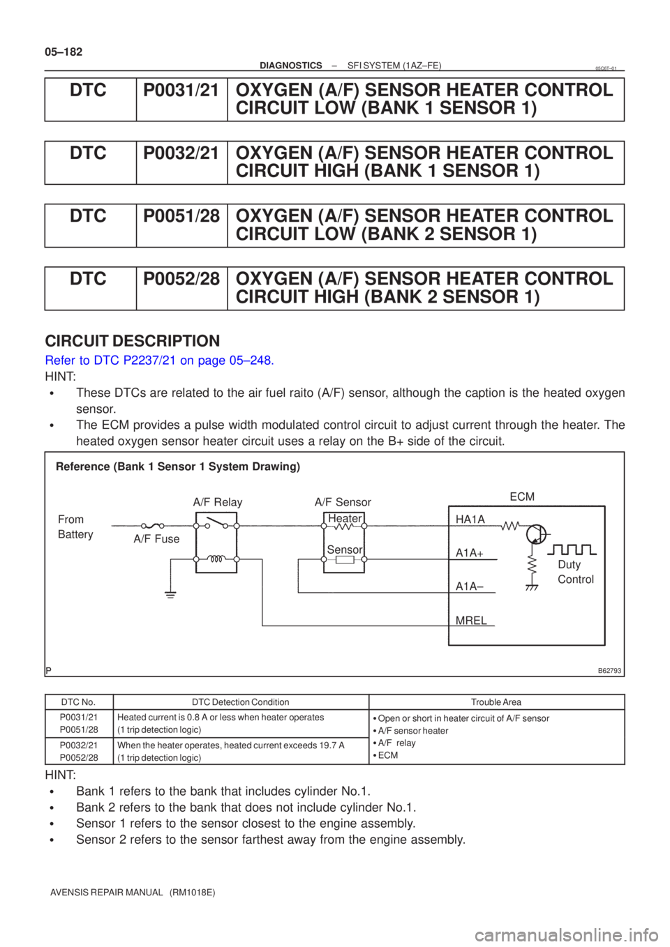
Reference (Bank 1 Sensor 1 System Drawing)A/F Sensor
A/F Relay
Heater
Sensor A1A+ HA1A
Duty
Control
ECM
From
Battery A/F Fuse
A1A±
MREL
05±182
±
DIAGNOSTICS SFI SYSTEM(1AZ±FE)
AVENSIS REPAIR MANUAL (RM1018E)
DTCP0031/21OXYGEN (A/F) SENSOR HEATER CONTROL CIRCUIT LOW (BANK 1 SENSOR 1)
DTCP0032/21OXYGEN (A/F) SENSOR HEATER CONTROL CIRCUIT HIGH (BANK 1 SENSOR 1)
DTCP0051/28OXYGEN (A/F) SENSOR HEATER CONTROL CIRCUIT LOW (BANK 2 SENSOR 1)
DTCP0052/28OXYGEN (A/F) SENSOR HEATER CONTROL CIRCUIT HIGH (BANK 2 SENSOR 1)
CIRCUIT DESCRIPTION
Refer to DTC P2237/21 on page 05±248.
HINT:
�These DTCs are related to the air fuel raito (A/F) sensor, although the caption is the heated oxygen
sensor.
�The ECM provides a pulse width modulated control circuit to adjust curre\
nt through the heater. The
heated oxygen sensor heater circuit uses a relay on the B+ side of the c\
ircuit.
DTC No.DTC Detection ConditionTrouble Area
P0031/21
P0051/28Heated current is 0.8 A or less when heater operates
(1 trip detection logic)�Open or short in heater circuit of A/F sensor
� A/F sensor heater
P0032/21
P0052/28When the heater operates, heated current exceeds 19.7 A
(1 trip detection logic)�A/F relay
� ECM
HINT:
�Bank 1 refers to the bank that includes cylinder No.1.
�Bank 2 refers to the bank that does not include cylinder No.1.
�Sensor 1 refers to the sensor closest to the engine assembly.
�Sensor 2 refers to the sensor farthest away from the engine assembly.
05C6T±01
Page 491 of 5135

A72920
Reference (Bank 1 Sensor 1 System Drawing)Heated Oxygen Sensor
EFI Relay
Heater
SensorOX1A HT1A
Duty
Control
ECM
From
Battery EFI Fuse
E2
EFI No. 2
Fuse
MREL
OX HT
E1
+B
±
DIAGNOSTICS SFI SYSTEM(1AZ±FSE)
05±331
AVENSIS REPAIR MANUAL (RM1018E)
CIRCUIT DESCRIPTION
Refer to DTC P0130 on page 05±363.
HINT:
The ECM provides a pulse width modulated control circuit to adjust current \
through the heater. The heated
oxygen sensor heater circuit uses a relay on the B+ side of the circuit.
DTC No.DTC Detection ConditionTrouble Area
P0031
P0037Heated current is 0.2 A or less when heater operates with +B >
10.5 V and < 11.5 V (1 trip detection logic)�Open in heater circuit of heated oxygen sensor
� Heated oxygen sensor heater
� EFI relay
P0037
P0051
P0057Heated current is 0.25 A or less when heater operates with +B
� 11.5 V (1 trip detection logic)
EFI relay
�EFI fuse
� EFI No. 2 fuse
� ECM
P0032
P0038
P0052
P0058
Heated current exceeds 2 A when heater operates.
(1 trip detection logic)�Short in heater circuit of heated oxygen sensor
� Heated oxygen sensor heater
� ECM
HINT:
�Bank 1 refers to the No. 1 and No. 4 cylinders.
�Bank 2 refers to the No. 2 and No. 3 cylinders.
�Sensor 1 refers to the sensor closest to the engine assembly.
�Sensor 2 refers to the sensor farthest away from the engine assembly.
WIRING DIAGRAM
Refer to DTC P0130 on page 05±363.
INSPECTION PROCEDURE
HINT:
�If different DTCs related to different systems that have terminal E2 as the ground terminal are output
simultaneously, terminal E2 may be open.
�Read freeze frame data using the hand±held tester. Freeze frame data records the engine conditions
when a malfunction is detected. When troubleshooting, it is useful for deter\
mining whether the vehicle
was running or stopped, the engine was warmed up or not, the air±fuel ra\
tio was lean or rich, etc. at
the time of the malfunction.
Page 2033 of 5135
A62173
Yellow Color Link
Timing Mark
A30867
A62174
SST
A62175
Seal Width
4 to 5 mm
Seal Packing
14±54
± ENGINE MECHANICALCHAIN SUB±ASSY (1ZZ±FE/3ZZ±FE)
AVENSIS REPAIR MANUAL (RM1018E)
(d) Install the timing chain to the camshaft timing sprockets
with the yellow color links aligned with the timing marks on
the camshaft timing sprockets.
29. INSTALL CHAIN TENSIONER SLIPPER
(a) Install the chain tensioner slipper with the bolt.
Torque: 19 N�m (194 kgf�cm, 14 ft�lbf)
30. INSTALL CRANKSHAFT POSITION SENSOR PLATE
NO.1
(a) Install the plate with the ºFº mark facing outward.
31. INSTALL TIMING GEAR COVER OIL SEAL
(a) Apply MP grease to a new oil seal lip.
(b) Using SST, tap in the oil seal until its surface is flush with
the timing chain cover edge.
SST 09223±22010
NOTICE:
Keep the lip free of foreign objects.
32. INSTALL TIMING CHAIN OR BELT COVER SUB±ASSY
(a) Remove any old packing (FIPG) material from the contact
surface.
Page 2034 of 5135

A65676
Timing Chain Cover side:
3 (0.118)3 (0.118)
A
ABB
C
C
7 (0.276)
4.5 (0.177)
12 (0.472)6 (0.236)
3 (0.118)
Width 4 (0.157)
A ± AB ± B
C ± C
08826±00100 or equivalent
08826±00080 or equivalent
(mm (in.))
A65677
A
A
AA
A
A
AAA B
B
B
± ENGINE MECHANICALCHAIN SUB±ASSY (1ZZ±FE/3ZZ±FE)
14±55
AVENSIS REPAIR MANUAL (RM1018E)
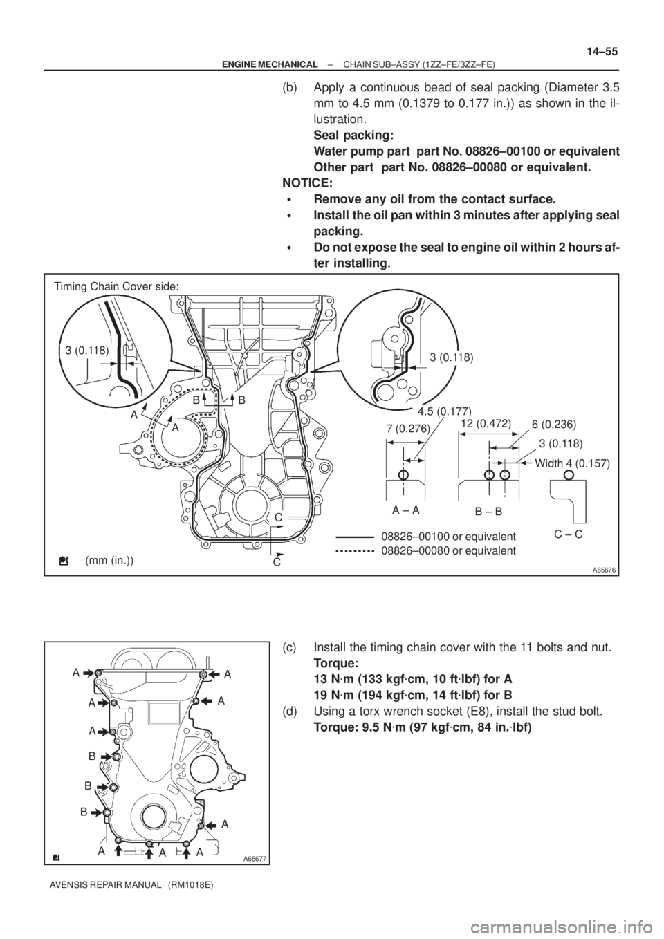
(b) Apply a continuous bead of seal packing (Diameter 3.5
mm to 4.5 mm (0.1379 to 0.177 in.)) as shown in the il-
lustration.
Seal packing:
Water pump part part No. 08826±00100 or equivalent
Other part part No. 08826±00080 or equivalent.
NOTICE:
�Remove any oil from the contact surface.
�Install the oil pan within 3 minutes after applying seal
packing.
�Do not expose the seal to engine oil within 2 hours af-
ter installing.
(c) Install the timing chain cover with the 11 bolts and nut.
Torque:
13 N�m (133 kgf�cm, 10 ft�lbf) for A
19 N�m (194 kgf�cm, 14 ft�lbf) for B
(d) Using a torx wrench socket (E8), install the stud bolt.
Torque: 9.5 N�m (97 kgf�cm, 84 in.�lbf)