Page 3501 of 5135

(b) Using SST and a hammer, tap out the guide bushing.
SST 09201±10000")
A77463
SST
A13100
A77464
SST
A77465
SST 14±46
± ENGINE MECHANICALCYLINDER HEAD ASSY
1AZ±FSE ENGINE REPAIR MANUAL (RM1019E)
(b) Using SST and a hammer, tap out the guide bushing.
SST 09201±10000 (09201±01050), 09950±70010
(09951±07100)
19. REMOVE EXHAUST VALVE GUIDE BUSH
(a) Gradually heat the cylinder head to 80 to 100�C (176 to
212�F).
(b) Using SST and a hammer, tap out the guide bushing.
SST 09201±10000 (09201±01050), 09950±70010
(09951±07100)
20. INSTALL INTAKE VALVE GUIDE BUSH
(a) Using a caliper gauge, measure the bushing bore diame-
ter of the cylinder head.
Diameter: 10.285 to 10.306 mm (0.4049 to 0.4057 in.)
(b) Install the STD bushing if the diameter is within specified
diameter.
HINT:
STD10.333 to 10.344 mm (0.4068 to 0.4072 in.)
(c) Using SST and a hammer, tap in a new guide bushing to
the specified protrusion height.
Protrusion height: 9.6 to 10.0 mm (0.3779 to 0.3937
in.)
SST 09201±10000 (09201±01050), 09950±70010
(09951±07100), 23801
(d) Using a sharp 5.5 mm reamer, ream the guide bushing to
obtain the standard specified clearance between the
guide bushing and valve stem.
Standard oil clearance:
0.025 to 0.060 mm (0.00098 to 0.00236 in.)
21. INSTALL EXHAUST VALVE GUIDE BUSH
(a) Using a caliper gauge, measure the bushing bore diame-
ter of the cylinder head.
Diameter: 10.285 to 10.306 mm (0.4049 to 0.4057 in.)
Page 3502 of 5135

(b) Install the STD bushing if the diameter is within specified
diameter.
HINT:
STD10.3")
A77466
SST
P16860
A13374
± ENGINE MECHANICALCYLINDER HEAD ASSY
14±47
1AZ±FSE ENGINE REPAIR MANUAL (RM1019E)
(b) Install the STD bushing if the diameter is within specified
diameter.
HINT:
STD10.333 to 10.344 mm (0.4068 to 0.4072 in.)
(c) Using SST and a hammer, tap in a new guide bushing to
the specified protrusion height.
Protrusion height: 9.6 to 10.0 mm (0.3779 to 0.3937
in.)
(d) Using a sharp 5.5 mm reamer, ream the guide bushing to
obtain the standard specified clearance between the
guide bushing and valve stem.
SST 09201±10000 (09201±01050), 09950±70010
(09951±07100), 23801
Standard oil clearance:
0.030 to 0.065 mm (0.00118 to 0.00256 in.)
22. INSPECT VALVE LIFTER
(a) Check the lifter diameter.
(1) Using a micrometer, measure the lifter diameter.
Lifter diameter:
30.966 to 30.976 mm (1.2191 to 1.2195 in.)
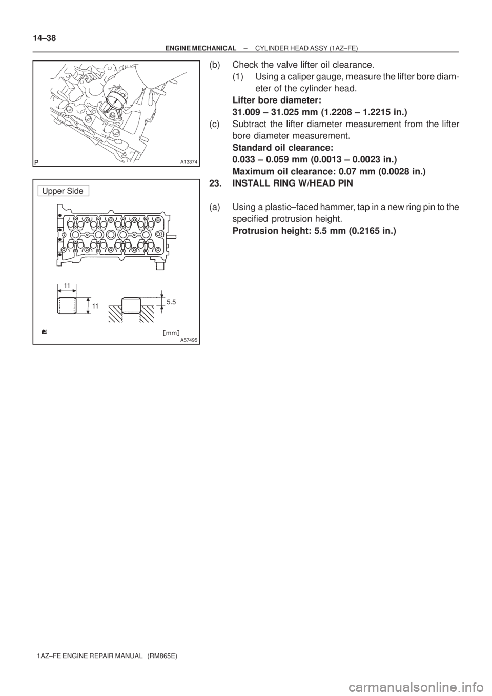
(b) Check the valve lifter oil clearance.
(1) Using a caliper gauge, measure the lifter bore diam-
eter of the cylinder head.
Lifter bore diameter:
31.009 to 31.025 mm (1.2208 to 1.2215 in.)
(c) Subtract the lifter diameter measurement from the lifter
bore diameter measurement.
Standard oil clearance:
0.033 to 0.059 mm (0.0013 to 0.0023 in.)
Maximum oil clearance: 0.08 mm (0.0032 in.)
Page 3503 of 5135
A77256
Upper Side
5.5
[mm]
A77257
Upper Side
[mm]
A77258
Exhaust Manifold Side
Seal Packing1.5 ± 2.5
(0.059 ± 0.098)
{mm (in.)} 14±48
± ENGINE MECHANICALCYLINDER HEAD ASSY
1AZ±FSE ENGINE REPAIR MANUAL (RM1019E)
23. INSTALL RING W/HEAD PIN
(a) Using a plastic±faced hammer, tap in a new ring pin to the
specified protrusion height.
Protrusion height: 5.5 mm (0.217 in.)
24. INSTALL RING PIN
(a) Using a plastic±faced hammer, tap in a new ring pin to the
specified protrusion height.
Protrusion height: 6.5 mm (0.256 in.)
25. INSTALL TIGHT PLUG
(a) Apply seal packing to the cylinder head as shown in the
illustration.
(b) Using SST, tap in plug to the specified protrusion height.
SST 09950±60010 (09951±00180), 09950±70010
(09951±07100)
Protrusion height: 1.5 to 2.5 mm (0.059 to 0.098 in.)
Page 3734 of 5135

14±37
1AZ±FE ENGINE REPAIR MANUAL (RM865E)
20. INSTALL INTAKE VALVE GUIDE BUSHING
(a) Using a caliper gauge, measure t")
SST
A36634
SST
A36635
P16860
± ENGINE MECHANICALCYLINDER HEAD ASSY (1AZ±FE)
14±37
1AZ±FE ENGINE REPAIR MANUAL (RM865E)
20. INSTALL INTAKE VALVE GUIDE BUSHING
(a) Using a caliper gauge, measure the bushing bore diame-
ter of the cylinder head.
Diameter: 10.285 ± 10.306 mm (0.4049 ± 0.4057 in.)
(b) Install the STD bushing if the diameter is within specified
diameter.
STD10.333 ± 10.344 mm (0.4068 ± 0.4072 in.)
(c) Using SST and a hammer, tap in a new guide bushing to
the specified protrusion height.
Protrusion height: 9.6 ± 10.0 mm (0.3779 ± 0.3937 in.)
SST 09201±01055, 09950±70010 (09951±07100),
23801
(d) Using a sharp 5.5 mm reamer, ream the guide bushing to
obtain the standard specified clearance between the
guide bushing and valve stem.
Standard oil clearance:
0.025 ± 0.060 mm (0.00098 ± 0.00236 in.)
21. INSTALL EXHAUST VALVE GUIDE BUSHINGS
(a) Using a caliper gauge, measure the bushing bore diame-
ter of the cylinder head.
Diameter: 10.285 ± 10.306 mm (0.4049 ± 0.4057 in.)
(b) Install the STD bushing if the diameter is within specified
diameter.
STD10.333 ± 10.344 mm (0.4068 ± 0.4072 in.)
(c) Using SST and a hammer, tap in a new guide bushing to
the specified protrusion height.
Protrusion height: 9.6 ± 10.0 mm (0.3779 ± 0.3937 in.)
(d) Using a sharp 5.5 mm reamer, ream the guide bushing to
obtain the standard specified clearance between the
guide bushing and valve stem.
SST 09201±01055, 09950±70010 (09951±07100),
23801
Standard oil clearance:
0.030 ± 0.065 mm (0.00118 ± 0.00256 in.)
22. INSPECT VALVE LIFTER
(a) Check the lifter diameter.
(1) Using a micrometer, measure the lifter diameter.
Lifter diameter:
30.966 ± 30.976 mm (1.2191 ± 1.2195 in.)
Page 3735 of 5135
A13374
�mm�
5.5
11 11
A57495
Upper Side 14±38
± ENGINE MECHANICALCYLINDER HEAD ASSY (1AZ±FE)
1AZ±FE ENGINE REPAIR MANUAL (RM865E)
(b) Check the valve lifter oil clearance.
(1) Using a caliper gauge, measure the lifter bore diam-
eter of the cylinder head.
Lifter bore diameter:
31.009 ± 31.025 mm (1.2208 ± 1.2215 in.)
(c) Subtract the lifter diameter measurement from the lifter
bore diameter measurement.
Standard oil clearance:
0.033 ± 0.059 mm (0.0013 ± 0.0023 in.)
Maximum oil clearance: 0.07 mm (0.0028 in.)
23. INSTALL RING W/HEAD PIN
(a) Using a plastic±faced hammer, tap in a new ring pin to the
specified protrusion height.
Protrusion height: 5.5 mm (0.2165 in.)
Page 3778 of 5135

14±35
1ZZ±FE,3ZZ±FE ENGINE REPAIR MANUAL
(RM923E)
24. INSTALL UNION
(a")
A62791
14 mm
25 mm
9 mm A
B
C
A62792
Adhesive
A62793
B
A
C
A62794
SST
± ENGINE MECHANICALCYLINDER HEAD ASSY (1ZZ±FE/3ZZ±FE)
14±35
1ZZ±FE,3ZZ±FE ENGINE REPAIR MANUAL
(RM923E)
24. INSTALL UNION
(a) Mark the standard position away from the edge, onto the
water hose union as shown in the illustration.
(b) Apply adhesive to the water hose union hole of the cylin-
der head.
Adhesive:
Part No. 08833±00070, THREE BOND 1324 or equiva-
lent.
(c) Using a press, press in a new water hose union until the
standard marks come to the level of the cylinder head sur-
face.
Standard protrusion:
A 29 mm (1.14 in.)
B 66.5 mm (2.62 in.)
C 24 mm (0.95 in.)
NOTICE:
�Install the water hose union within 3 minutes after ap-
plying adhesive.
�Do not put into coolant within an hour after installing.
25. INSTALL VALVE GUIDE BUSH
(a) Gradually heat the cylinder head to 80 ± 100�C (176 ±
212�F).
(b) Using SST and a hammer, tap in a new guide bushing to
the specified protrusion height.
SST 09201±10000, 09201±01055, 09950±70010
(09951±07100)
Protrusion height: 8.7 ± 9.1 mm (0.342 ± 0.358 in.)
Page 3790 of 5135

14±13
1ZZ±FE,3ZZ±FE ENGINE REPAIR MANUAL
(RM923E)
39. INSPECT CAMSHAFT
(a) Inspect camshaft for runout.
(1) Place the")
EM1628
EM2011
EM2538
± ENGINE MECHANICALPARTIAL ENGINE ASSY (1ZZ±FE/3ZZ±FE)
14±13
1ZZ±FE,3ZZ±FE ENGINE REPAIR MANUAL
(RM923E)
39. INSPECT CAMSHAFT
(a) Inspect camshaft for runout.
(1) Place the camshaft on V±blocks.
(2) Using a dial indicator, measure the circle runout at
the center journal.
Maximum circle runout: 0.03 mm (0.0012 in.)
(b) Inspect cam lobes.
(1) Using a micrometer, measure the cam lobe height.
Standard cam lobe height:
Intake 44.333 ± 44.433 mm (1.7454 ± 1.7493 in.)
Exhaust 43.761 ± 43.861 mm (1.7229 ± 1.7268 in.)
Minimum cam lobe height:
Intake 44.18 mm (1.7394 in.)
Exhaust 43.61 mm (1.7169 in.)
(c) Inspect camshaft journals.
(1) Using a micrometer, measure the journal diameter.
No. 1 journal diameter:
34.449 ± 34.465 mm (1.3563 ± 1.3569 in.)
Others journal diameter:
22.949 ± 22.965 mm (0.9035 ± 0.9041 in.)
If the journal diameter is not as specified, check the oil clear-
ance.
40. INSTALL CYLINDER BLOCK WATER DRAIN COCK SUB±ASSY
(a) Apply two or three threads of adhesive to the drain union, and install it within 3 minutes.
Torque: 20 N�m (204 kgf�cm15 ft�lbf)
(b) After applying the specified torque, rotate the drain union clockwise until its drain port faces downward.
NOTICE:
�Do not put into coolant in an hour after the installation.
�Do not rotate the drain union more than 360� in (b), and never loosen it after setting the union
correctly.
41. INSTALL OIL STRAINER SUB±ASSY
(a) Install a new gasket and the oil strainer with the 2 nuts and a bolt.
Torque: 9.0 N�m (92 kgf�cm, 80 in.�lbf)
Page 3822 of 5135
A56687
Cylinder Head Side: Lower Side:
Front Side:
A
B 11 m m20 mm
14 mm 8 mm
AAAA
B B
14±54
± ENGINE MECHANICALCYLINDER BLOCK (1CD±FTV)
1CD±FTV ENGINE REPAIR MANUAL (RM927E)
22. INSTALL RING PIN
(a) Using a plastic±faced hammer, tap in new ring pins to the
specified protrusion height.
Protrusion height:
A: 7.0 mm (0.2755 in.)
B: 13 mm (0.5118 in.)
![TOYOTA AVENSIS 2005 Service Repair Manual A77256
Upper Side
5.5
[mm]
A77257
Upper Side
[mm]
A77258
Exhaust Manifold Side
Seal Packing1.5 ± 2.5
(0.059 ± 0.098)
{mm (in.)} 14±48
± ENGINE MECHANICALCYLINDER HEAD ASSY
1AZ±FSE ENGINE REPAIR](/manual-img/14/57441/w960_57441-3502.png "TOYOTA AVENSIS 2005 Service Repair Manual A77256
Upper Side
5.5
[mm]
A77257
Upper Side
[mm]
A77258
Exhaust Manifold Side
Seal Packing1.5 ± 2.5
(0.059 ± 0.098)
{mm (in.)} 14±48
± ENGINE MECHANICALCYLINDER HEAD ASSY
1AZ±FSE ENGINE REPAIR")

1CD±FTV ENGINE REPAIR MANUAL (RM927E)
22. INSTALL RING P")