Page 40 of 5135

(6)When disposing the vehicle or the horn button a")
D25096
Example:CORRECTWRONG
Z13950
Example:
D27522
Example: CORRECT WRONG
±
INTRODUCTION REPAIR INSTRUCTION
01±11
AVENSIS REPAIR MANUAL (RM1018E)
(6)When disposing the vehicle or the horn button assembly alone, the airbag\
should be inflated us-
ing an SST before disposal (See page 60±19).
Perform the operation in a safe place away from electrical noise.
(d)INSTRUMENT PANEL PASSENGER AIRBAG ASSEMBLY (1)Always place a removed or new instrument panel passenger airbag assembly\
with the airbaginflation direction facing upward. Placing the airbag assembly with the airbag inflation direction
facing downward could cause a serious accident if the airbag deploys.
(2)Never measure the resistance of the airbag squib (This may cause the airbag to inflate, which is very dangerous).
(3)Grease should not be applied to the instrument panel passenger airbag assembly\
and the airbag door should not be cleaned with detergents of any kind.
(4)Store the airbag assembly where the ambient temperature remains below 93 �C (200 �F), without
high humidity and away from electrical noise.
(5)When using electric welding, disconnect the airbag connector (4 yellow pins\
) installed on the as- sembly before starting work.
(6)When disposing of a vehicle or the airbag assembly unit, the airbag should be deployed using\
SST before disposal (See page 60±30).
Activate in a safe place away from electrical noise.
Page 42 of 5135

(f)INSTRUMENT PANEL LOWER AIRBAG ASSEMBLY
(1)Always store a removed or new inst")
D30399
Example:CORRECT WRONG
D30398
Example:
±
INTRODUCTION REPAIR INSTRUCTION
01±13
AVENSIS REPAIR MANUAL (RM1018E)
(f)INSTRUMENT PANEL LOWER AIRBAG ASSEMBLY
(1)Always store a removed or new instrument panel lower airbag assembly with the \
airbag inflatingdirection facing upward.
Placing the airbag assembly with the airbag inflation direction facing d\
ownward could cause a
serious accident if the airbag inflates.
(2)Never measure the resistance of the airbag squib (This may cause the ai\
rbag to inflate, which is very dangerous.).
(3)Grease should not be applied to the instrument panel lower airbag assembly and\
the airbag door should not be cleaned with detergents of any kind.
(4)Store the instrument panel lower airbag assembly where the ambient temperature remains be- low 93 �C (200 �F), without high humidity and away from electrical noise.
(5)When using electric welding, first disconnect the airbag connector (2 yello\
w pins) installed on the
instrument panel lower airbag assembly before starting work.
(6)When disposing of a vehicle or the instrument panel lower airbag assembly alone, the airbag should be inflated using an SST before disposal (See page 60±55).
Perform the operation in a safe place away from electrical noise.
(g) CURTAIN SHIELD AIRBAG ASSEMBLY (1) Always place the removed or new curtain shield airbag assembly in a clear plastic bag, and keepit in a safe place.
NOTICE:
Protection bag is not re±useable.
CAUTION:
Never disassemble the curtain shield airbag assembly. (2) Never measure the resistance of the airbag squib (This may cause the airbag to inflate, whichis very dangerous).
Page 198 of 5135

ENGINE HOOD/DOOR
TORQUE SPECIFICATION
Part TightenedN�mkgf�cmft�lbf
HOOD
Hood hinge x Hood1313310
Hood hing")
031GG±01
± SERVICE SPECIFICATIONSENGINE HOOD/DOOR
03±73
AVENSIS REPAIR MANUAL (RM1018E)
ENGINE HOOD/DOOR
TORQUE SPECIFICATION
Part TightenedN�mkgf�cmft�lbf
HOOD
Hood hinge x Hood1313310
Hood hinge x Body5.55649 in.�lbf
Hood lock x Hood8.08271 in.�lbf
FRONT DOOR
Door check x Body3030622
Door check x Door panel5.55646 in.�lbf
Door frame sub±assy rear lower x Door panel8.08271 in.�lbf
Door glass x Front door window regulator5.55649 in.�lbf
Door hinge x Body2626519
Door hinge x Door panel2626519
Door lock x Door panel5.05144 in.�lbf
Door lock striker x Body2323517
Door outside handle cover x Door panel7.07162 in.�lbf
Door outside handle frame x Door panel4.04135 in.�lbf
Outer view mirror x Door panel101027
Window regulator x Door panel8.08271 in.�lbf
REAR DOOR
Door check x Body3030622
Door check x Door panel5.55649 in.�lbf
Door hinge x Body2626519
Door hinge x Door panel2626519
Door lock x Door panel5.05144 in.�lbf
Door lock striker x Body2323517
Door outside handle cover x Door panel4.04135 in.�lbf
Door outside handle frame x Door panel7.07162 in.�lbf
Window division bar sub±assy x Door panel5.55649 in.�lbf
LAGGAGE COMPERTMENT DOOR
Back door striker assy x Body11.51208.0
Luggage compertment door x Hinge7.07062 in.�lbf
Luggage lock assy x Luggage compertment door5.05144 in.�lbf
Luggage compertment outside garnish x Luggage compertment door4.94943 in.�lbf
BACK DOOR (LIFTBACK MODEL)
Back door femaie stopper x Door panel5.55649 in.�lbf
Back door hinge assy x Body19.520014
Back door hinge assy x Door panel19.520014
Back door lock assy x Door panel8.08271 in.�lbf
Back door lock Striker x Body11.51208.0
Back door stay sub±assy x Body7.07162 in.�lbf
Back door stay sub±assy x Door panel2222416
Center stop lamp assy x Door panel5.55649 in.�lbf
BACK DOOR (WAGON MODEL)
Back door femaie stopper x Door panel5.55649 in.�lbf
Back door hinge assy x Body19.520014
Back door hinge assy x Door panel19.520014
Back door lock assy x Door panel8.08271 in.�lbf
Back door lock Striker x Body11.51208.0
Back door stay sub±assy x Body7.07162 in.�lbf
Page 199 of 5135
03±74
± SERVICE SPECIFICATIONSENGINE HOOD/DOOR
AVENSIS REPAIR MANUAL (RM1018E)Part Tightenedft�lbf kgf�cm N�m
Back door stay sub±assy x Door panel2222416
Center stop lamp assy x Door panel5.55649 in.�lbf
Page 1548 of 5135
±
DIAGNOSTICS NAVIGATION SYSTEM
05±1487
AVENSIS REPAIR MANUAL (RM1018E)
GPS MARK DOES NOT APPEAR
INSPECTION PROCEDURE
1CHECK MARK DISPLAY
(a)Check that the malfunction disappears when placing the vehicle outdoors with \
a good view.
Standard: GPS mark is displayed.
HINT:
At the place surrounded by the architecture, the vehicle cannot receive \
the GPS radio wave.
OKSYSTEM OK
NG
2CHECK OPTIONAL COMPONENT
(a)Check for optional component. (1)Check if there are any optional components on the vehicle.
Standard: There are no optional components on the vehicle.
(2)Check if there is anything such as film stuck to the window or any metal obje\
cts on the instrument
panel.
Standard: There is nothing such as film stuck to the window or any metal objects on the instru-
ment panel.
NGEFFECT FROM OPTIONAL COMPONENT
OK
3REPLACE NAVIGATION ANTENNA ASSY (See page 67±28)
Standard: Normally returns. NG REPLACE NAVIGATION ECU (See page 67±27)
OK
SYSTEM OK
05C3R±01
Page 1557 of 5135
05C88±01
�����
�����
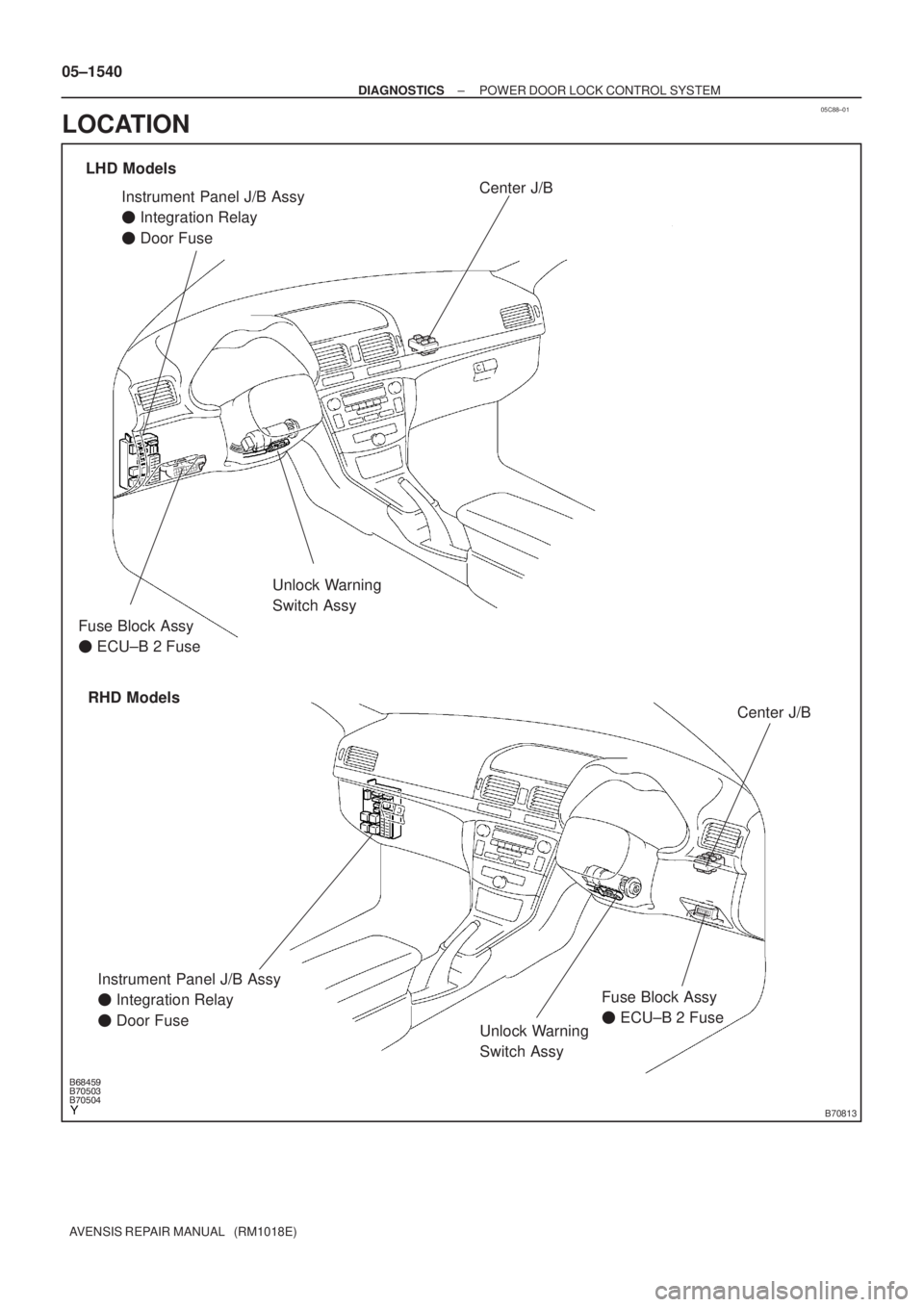
�����B70813
Unlock Warning
Switch Assy
Instrument Panel J/B Assy
� Integration Relay
� Door Fuse
Unlock Warning
Switch Assy
LHD Models
RHD ModelsCenter J/B
Center J/B
Fuse Block Assy
� ECU±B 2 Fuse
Instrument Panel J/B Assy
� Integration Relay
� Door FuseFuse Block Assy
� ECU±B 2 Fuse 05±1540
± DIAGNOSTICSPOWER DOOR LOCK CONTROL SYSTEM
AVENSIS REPAIR MANUAL (RM1018E)
LOCATION
Page 1589 of 5135
B66771
KSW
W±B8 U1
Unlock Warning Switch Assy
W±B
IP5
+B GROUND 1
W±R W±B
2
1Instrument Panel J/B Assy
PRG
RDA 16
2PRG
RDA D6
Door Control Receiver
7Integration
Relay
IC2 I14 3 G±Y
L±W 16
7
To
Battery
DA Y
IO*
1
6 8
Center
J/BIC2 G±Y
L±W
CA CD
AJ16
J/C LHD Models
19 I14
A W±B
IL*
2*1: Gasoline Engine
*2: 1CD±FTV
± DIAGNOSTICSWIRELESS DOOR LOCK CONTROL SYSTEM
05±1575
AVENSIS REPAIR MANUAL (RM1018E)
ONLY WIRELESS CONTROL FUNCTION DOES NOT OPERATE
(PREPARE NEW OR NORMAL TRANSMITTER OF THE SAME
TYPE VEHICLE)
CIRCUIT DESCRIPTION
The door control receiver receives a signal from the transmitter and sends this signal to the integration relay.
Then, the integration relay controls door operation by sending a door LOCK/UNLOCK signal and a luggage
door (back door) unlock signal to each door lock motor.
WIRING DIAGRAM
05BNB±01
Page 1590 of 5135
B66770
KSW
W±B8 U1
Unlock Warning Switch Assy
IP 5
+B GROUND 1
W±R W±B
2 1Instrument Panel J/B Assy
PRG
RDA 16
2PRG
RDA D6
Door Control Receiver
7Integration
Relay
IC2 I14 3
G±Y
L±W 16
7
To
Battery
DA Y*
2
IKIC2 G±Y
L±W
13 6
CF CA19 RHD Models
DJ22
J/C*
2
D
Center J/B
W±B Y*2
*1: 1AZ±FE
*
2: Except 1AZ±FEY*
1
A
J15
J/CI14 05±1576
± DIAGNOSTICSWIRELESS DOOR LOCK CONTROL SYSTEM
AVENSIS REPAIR MANUAL (RM1018E)


GPS MARK DOES NOT APPEAR
INSPECTION PROCEDURE
1CHECK MARK DISPLAY
(a)Check that the malfunction disappears when placing the")