Page 3879 of 5135
A79111
OCV Signal Waveform1 msec./Division 5 V/
Division
GND
(A)(A) (A)
E13
OC1 +OC1±
05±176
±
DIAGNOSTICS SFI SYSTEM(1AZ±FE)
AVENSIS REPAIR MANUAL (RM1018E)
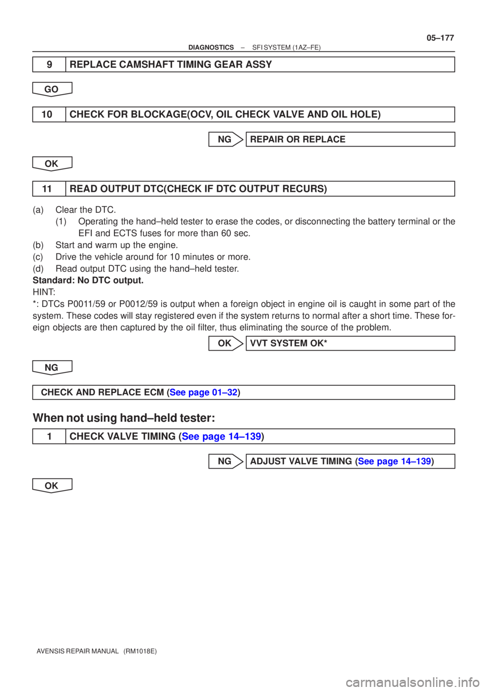
4CHECK ECM(OCV SIGNAL)
(a)Inspection using the oscilloscope.
(b)During idling, check the waveform between the terminals of the E13 ECM connector.
Standard:
Symbols (Terminal No.)Specified condition
OC1+ (E13±15) ± OC1± (E13±14)Correct waveform is as shown
HINT:
The waveform frequency (A) is lengthened as the engine speed
becomes higher.
NGCHECK AND REPLACE ECM (See page 01±32)
OK
5CHECK OIL CONTROL VALVE FILTER
NGREPLACE OIL CONTROL VALVE FILTER
OK
6CHECK CAMSHAFT TIMING OIL CONTROL VALVE ASSY(OCV) (See page 10±20)
OKGo to step 8
NG
7REPLACE CAMSHAFT TIMING OIL CONTROL VALVE ASSY(OCV)
GO
8CHECK CAMSHAFT TIMING GEAR ASSY (See page 14±171)
OK Go to step 10
NG
Page 3880 of 5135

±
DIAGNOSTICS SFI SYSTEM(1AZ±FE)
05±177
AVENSIS REPAIR MANUAL (RM1018E)
9REPLACE CAMSHAFT TIMING GEAR ASSY
GO
10CHECK FOR BLOCKAGE(OCV, OIL CHECK VALVE AND OIL HOLE)
NGREPAIR OR REPLACE
OK
11READ OUTPUT DTC(CHECK IF DTC OUTPUT RECURS)
(a)Clear the DTC. (1)Operating the hand±held tester to erase the codes, or disconnecting the batter\
y terminal or the
EFI and ECTS fuses for more than 60 sec.
(b)Start and warm up the engine.
(c)Drive the vehicle around for 10 minutes or more.
(d)Read output DTC using the hand±held tester.
Standard: No DTC output.
HINT:
*: DTCs P0011/59 or P0012/59 is output when a foreign object in engine oil is caught\
in some part of the
system. These codes will stay registered even if the system returns to normal a\
fter a short time. These for-
eign objects are then captured by the oil filter, thus eliminating the source of the problem.
OKVVT SYSTEM OK*
NG
CHECK AND REPLACE ECM (See page 01±32)
When not using hand±held tester:
1CHECK VALVE TIMING (See page 14±139)
NGADJUST VALVE TIMING (See page 14±139)
OK
Page 3881 of 5135

A76968
C2
(±) (+)
Camshaft Timing Oil Control Valve
05±178
± DIAGNOSTICSSFI SYSTEM (1AZ±FE)
AVENSIS REPAIR MANUAL (RM1018E)
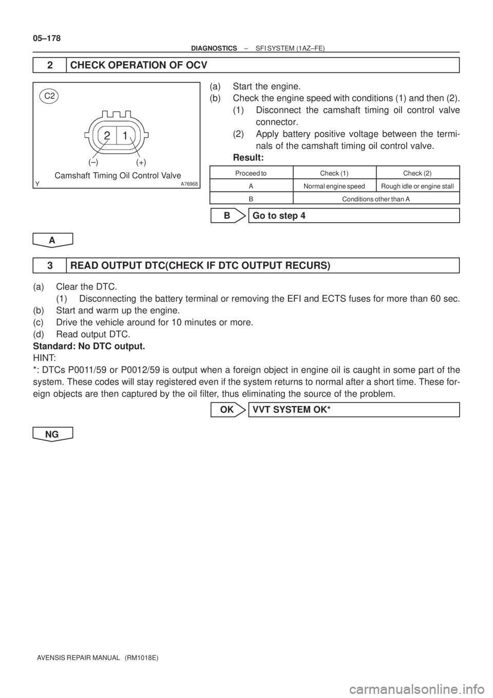
2 CHECK OPERATION OF OCV
(a) Start the engine.
(b) Check the engine speed with conditions (1) and then (2).
(1) Disconnect the camshaft timing oil control valve
connector.
(2) Apply battery positive voltage between the termi-
nals of the camshaft timing oil control valve.
Result:
Proceed toCheck (1)Check (2)
ANormal engine speedRough idle or engine stall
BConditions other than A
B Go to step 4
A
3 READ OUTPUT DTC(CHECK IF DTC OUTPUT RECURS)
(a) Clear the DTC.
(1) Disconnecting the battery terminal or removing the EFI and ECTS fuses for more than 60 sec.
(b) Start and warm up the engine.
(c) Drive the vehicle around for 10 minutes or more.
(d) Read output DTC.
Standard: No DTC output.
HINT:
*: DTCs P0011/59 or P0012/59 is output when a foreign object in engine oil is caught in some part of the
system. These codes will stay registered even if the system returns to normal after a short time. These for-
eign objects are then captured by the oil filter, thus eliminating the source of the problem.
OK VVT SYSTEM OK*
NG
Page 3882 of 5135
A79111
OCV Signal Waveform1 msec./Division 5 V/
Division
GND
(A)(A) (A)
E13
OC1 +OC1±
±
DIAGNOSTICS SFI SYSTEM(1AZ±FE)
05±179
AVENSIS REPAIR MANUAL (RM1018E)
4CHECK ECM(OCV SIGNAL)
(a)Inspection using the oscilloscope.
(b)During idling, check the waveform between the terminals
of the E13 ECM connector.
Standard:
Symbols (Terminal No.)Specified condition
OC1+ (E13±15) ± OC1± (E13±14)Correct waveform is as shown
HINT:
The waveform frequency (A) is lengthened as the engine speed
becomes higher.
NGCHECK AND REPLACE ECM (See page 01±32)
OK
5CHECK OIL CONTROL VALVE FILTER
NGREPLACE OIL CONTROL VALVE FILTER
OK
6CHECK CAMSHAFT TIMING OIL CONTROL VALVE ASSY(OCV) (See page 10±20)
OKGo to step 8
NG
7REPLACE CAMSHAFT TIMING OIL CONTROL VALVE ASSY(OCV)
GO
8CHECK CAMSHAFT TIMING GEAR ASSY (See page 14±171)
OK Go to step 10
NG
Page 3883 of 5135
05±180
±
DIAGNOSTICS SFI SYSTEM(1AZ±FE)
AVENSIS REPAIR MANUAL (RM1018E)
9REPLACE CAMSHAFT TIMING GEAR ASSY
GO
10CHECK FOR BLOCKAGE(OCV, OIL CHECK VALVE AND OIL HOLE)
NGREPAIR OR REPLACE
OK
11READ OUTPUT DTC(CHECK IF DTC OUTPUT RECURS)
(a)Clear the DTC. (1)Disconnecting the battery terminal or removing the EFI and ECTS fuses for more than 6\
0 sec.
(b)Start and warm up the engine.
(c)Drive the vehicle around for 10 minutes or more.
(d)Read output DTC.
Standard: No DTC output.
HINT:
*: DTCs P0011/59 or P0012/59 is output when a foreign object in engine oil is caught in some part of \
the
system. These codes will stay registered even if the system returns to normal a\
fter a short time. These for-
eign objects are then captured by the oil filter, thus eliminating the source of the problem.
OKVVT SYSTEM OK*
NG
CHECK AND REPLACE ECM (See page 01±32)
Page 3894 of 5135

±
DIAGNOSTICS SFI SYSTEM(1AZ±FE)
05±159
AVENSIS REPAIR MANUAL (RM1018E)
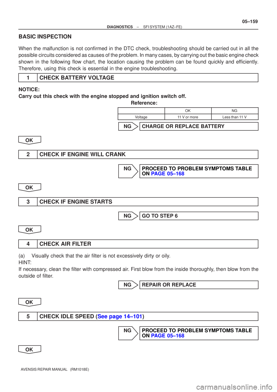
BASIC INSPECTION
When the malfunction is not confirmed in the DTC check, troubleshooting \
should be carried out in all the
possible circuits considered as causes of the problem. In many cases, by carrying out the basic engine check
shown in the following flow chart, the location causing the problem can be found quickly and efficiently.
Therefore, using this check is essential in the engine troubleshooting.
1CHECK BATTERY VOLTAGE
NOTICE:
Carry out this check with the engine stopped and ignition switch off.
Reference:
OKNG
Voltage11 V or moreLess than 11 V
NGCHARGE OR REPLACE BATTERY
OK
2CHECK IF ENGINE WILL CRANK
NGPROCEED TO PROBLEM SYMPTOMS TABLE ON PAGE 05±168
OK
3CHECK IF ENGINE STARTS
NGGO TO STEP 6
OK
4CHECK AIR FILTER
(a)Visually check that the air filter is not excessively dirty or oily.
HINT:
If necessary, clean the filter with compressed air. First blow from the inside thoroughly, then blow from the
outside of filter. NGREPAIR OR REPLACE
OK
5CHECK IDLE SPEED (See page 14±101)
NGPROCEED TO PROBLEM SYMPTOMS TABLE ON PAGE 05±168
OK
Page 4042 of 5135

03−1 6
−
SERVICE SPECIFICATIONS ENGINE MECHANICAL
AVENSIS Supplement (RM1045E) Part Tightened
ft �lbf
kgf �cm
N �m
Intake manifold x Cylinder head2120915
Power steering idle pulley bracket x Cylinder head
(See page 14 −108) Bolt A
Bolt B
72
39734
39853
29
Intake manifold insulator No. 1 x Intake manifold5.05144 in.�lbf
Injection pipe x Common rail
With SST
Without SST
31
34316
34723
25
Injection pipe x Injector
For used pipe With SST Without SST
For new pipe With SST
Without SST
36
40
31
34372
408
316
34727
30
23
25
Injection pipe clamp x Intake manifold5.05144 in.�lbf
Fuel inlet pipe x Common rail
With SST
Without SST
31
34316
34723
25
Fuel inlet pipe x injection pump With SST
Without SST
31
34316
34723
25
Nozzle leakage pipe No.2 x Cylinder head cover sub −assy8.89078 in. �lbf
Nozzle leakage pipe No.2 x Cylinder head8.89078 in. �lbf
Vacuum pump x Cylinder head2121415
EGR valve assy x Cylinder head1818413
Intake air connector with diesel throttle body x Intake manifold2120915
Water inlet x Cylinder block8.89078 in. �lbf
Water outlet sub −assy x Cylinder head2120915
Exhaust manifold x Cylinder head4747434
EGR pipe sub −assy x Cylinder head Bolt
Nut37
25375
25027
18
Vacuum pump oil pipe x Cylinder block Bolt Nut21
8.8214 9015
78 in. �lbf
Vacuum transmitting pipe No. 2 x Manifold converter
For nut With SST
Without SST
For bolt
27
30
25275
306
25520
22
18
Vacuum transmitting pipe No. 1 x Manifold converter
For nut With SST Without SST
For bolt
27
30
25275
306
25520
22
18
Exhaust gas temperature sensor x Manifold converter With SST
Without SST27
30275
30620
22
Exhaust gas temperature sensor x Vacuum transmitting pipe No. 26.46557 in.�lbf
Oil filter bracket x Oil pan sub −assy3434725
V −ribbed belt tensioner bracket x Cylinder block2020415
V −ribbed belt tensioner assy x Oil pump3131623
Generator bracket No.1 x Cylinder block3737727
Idler pulley Sub −assy x V −ribbed belt tensioner assy4040830
Engine mounting bracket RR x Engine mounting insulator RR6465347
Engine mounting bracket FR x Engine mounting insulator FR6465347
Drive shaft bearing bracket x Cylinder block6465347
Rear end plate x Cylinder block8.48674 in. �lbf
Flywheel x Crankshaft7172052
Engine mounting member sub −assy center x Body4545933
Page 4117 of 5135

05HHY−01
05 −8
−
DIAGNOSTICS SFI SYSTEM (2AZ−FSE)
AVENSIS Supplement (RM 1045E)
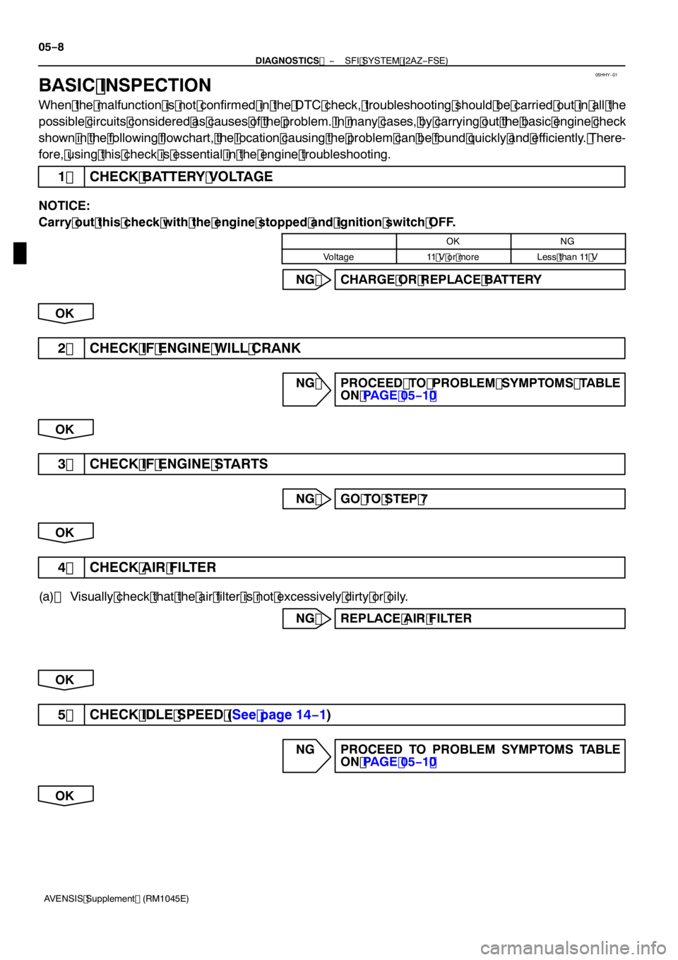
BASIC INSPECTION
When the malfunction is not confirmed in the DTC check, troubleshooting should be carried out in all the
possible circuits considered as causes of the problem. In many cases, by carrying out the basic engine check
shown in the following flowchart, the location causing the problem can be found quickly and efficiently. There-
fore, using this check is essential in the engine troubleshooting.
1 CHECK BATTERY VOLTAGE
NOTICE:
Carry out this check with the engine stopped and ignition switch OFF.
OKNG
Voltage11 V or moreLess than 11 V
NG CHARGE OR REPLACE BATTERY
OK
2 CHECK IF ENGINE WILL CRANK
NG PROCEED TO PROBLEM SYMPTOMS TABLE ON PAGE 05 −1 0
OK
3 CHECK IF ENGINE STARTS
NG GO TO STEP 7
OK
4 CHECK AIR FILTER
(a) Visually check that the air filter is not excessively dirty or oily. NG REPLACE AIR FILTER
OK
5 CHECK IDLE SPEED (See page 14−1 )
NG PROCEED TO PROBLEM SYMPTOMS TABLE
ON PAGE 05 −1 0
OK