Page 298 of 5135
05±164
±
DIAGNOSTICS SFI SYSTEM (1AZ±FE)
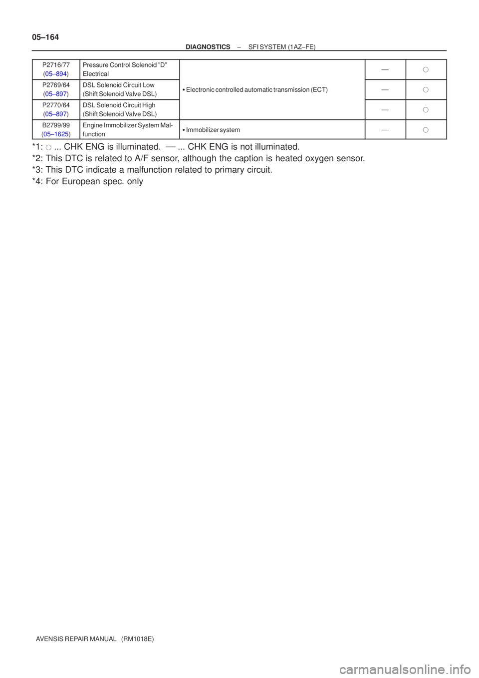
AVENSIS REPAIR MANUAL (RM1018E) P2716/77
(05±894)
Pressure Control Solenoid ºDº
Electrical��
P2769/64(05±897)DSL Solenoid Circuit Low
(Shift Solenoid Valve DSL)� Electronic controlled automatic transmission (ECT)��
P2770/64
(05±897)DSL Solenoid Circuit High
(Shift Solenoid Valve DSL)��
B2799/99
(05±1625)Engine Immobilizer System Mal-
function� Immobilizer system��
*1: � ... CHK ENG is illuminated. � ... CHK ENG is not illuminated.
*2: This DTC is related to A/F sensor, although the caption is heated oxygen sensor.
*3: This DTC indicate a malfunction related to primary circuit.
*4: For European spec. only
Page 4107 of 5135

AVENSIS Supplement (RM 1045E)
DTC No.
(See Page) Memory
*
1
CHK ENG
Trouble Area
Detection Item
P2 138
(05 −224)Throttle Pedal Position Sensor/
Switch")
05−40
−
DIAGNOSTICS SFI SYSTEM (2AZ−FSE)
AVENSIS Supplement (RM 1045E)
DTC No.
(See Page) Memory
*
1
CHK ENG
Trouble Area
Detection Item
P2 138
(05 −224)Throttle Pedal Position Sensor/
Switch ”D”/”E” Voltage Correla-
tionSVPA and VPA2 circuits are short −circuit
S Accelerator pedal position sensor
S ECM
ff
P2 195 *3
(05 −82)
Oxygen Sensor Signal Stuck
Lean (Bank 1Sensor 1)*7
SOpen or short in heated oxygen sensor circuit
S Heated oxygen sensor (Bank 1Sensor 1)*7
SHeated oxygen sensor heater (Bank 1Sensor 1)*7
SEFI relay
S Air induction system
S Fuel pressure
S Injector
S ECMff
P2 196 *3
(05 −82)
Oxygen Sensor Signal Stuck
Rich (Bank 1Sensor 1)*7
SOpen or short in heated oxygen sensor circuit
S Heated oxygen sensor (Bank 1Sensor 1)*7
SHeated oxygen sensor heater (Bank 1Sensor 1)*7
SEFI relay
S Air induction system
S Fuel pressure
S Injector
S ECMff
P2 197 *3
(05 −82)
Oxygen Sensor Signal Stuck
Lean (Bank 2 Sensor 1)*8
SOpen or short in heated oxygen sensor circuit
S Heated oxygen sensor (Bank 2 Sensor 1)*8
SHeated oxygen sensor heater (Bank 2 Sensor 1)*8
SEFI relay
S Air induction system
S Fuel pressure
S Injector
S ECMff
P2 198 *3
(05 −82)
Oxygen Sensor Signal Stuck
Rich (Bank 2 Sensor 1)*8
SOpen or short in heated oxygen sensor circuit
S Heated oxygen sensor (Bank 2 Sensor 1)*8
SHeated oxygen sensor heater (Bank 2 Sensor 1)*8
SEFI relay
S Air induction system
S Fuel pressure
S Injector
S ECMff
P27 16*4
(05 −622)
Pressure Control Solenoid ”D”
ElectricalSElectronic controlled automatic transmission (ECT)ff
B2799
(*6)Engine Immobilizer System Mal-
functionSImmobilizer system�f
*1:����CHK ENG (Check engine warning light) dese not illuminate,f ���CHK ENG (Check engine warning
light) illuminates.
*
2: CHK ENG (Check engine warning light) illuminates or blinks.
*
3: For Euro −OBD vehicles only.
*
4: For A/T only.
*
5: See page 05 −1714 of Pub. No. RM 1018E AVENSIS.
*
6: See page 05 −1628 of Pub. No. RM 1018E AVENSIS.
*
7: Bank 1refers to the No. 1and No. 4 cylinders.
*
8: Bank 2 refers to the No. 2 and No. 3 cylinders.
Page 4303 of 5135
(From September, 2003)
AVENSIS Supplement (RM 1045E)
DTC No.
(See Page) Memory
*
1
CHK ENG
Trouble Area
Detection Item
P2226
(05 −482)Barometric Press")
05−304
−
DIAGNOSTICS ECD SYSTEM (1CD −FTV)(From September, 2003)
AVENSIS Supplement (RM 1045E)
DTC No.
(See Page) Memory
*
1
CHK ENG
Trouble Area
Detection Item
P2226
(05 −482)Barometric Pressure Circuitff
P2227
(05 −483)Barometric Pressure Circuit
Range/Performance
ECM
ff
P2228
(05 −482)Barometric Pressure Circuit Low
InputSECM
ff
P2229
(05 −482)Barometric Pressure Circuit High
Inputff
P2237
(05 −484)Oxygen (A/F) Sensor Pumping
Current Circuit/Open (For A/F
Sensor) (Bank 1Sensor 1)
SECMff
P2238
(05 −484)Oxygen (A/F) Sensor Pumping
Current Circuit/Low (For A/F
Sensor) (Bank 1Sensor 1)SOpen or short in A/F sensor circuit
S A/F sensor
S
A/F sensor heater
ff
P2239
(05 −484)Oxygen (A/F) Sensor Pumping
Current Circuit/High (For A/F
Sensor) (Bank 1Sensor 1)
SA/Fsensorheater
SA/F sensor heater relay
S A/F sensor heater and relay circuit
S ECM
ff
B2799Engine Immobilizer System Mal-
functionSImmobilizer system�f
*1 : Check that the check engine warning light (CHK ENG) is illuminated.
Page 4936 of 5135
–
DIAGNOSTICS SFI SYSTEM (1ZZ–FE/3ZZ–FE)(From February, 2004)
05–33
AVENSIS REPAIR MANUAL SUPPLEMENT
(RM1098E)DTC No.
(See Page) Memory
*1
MIL
Trouble Area
Detection Item
P2770
( 05–289 )Torque Converter Clutch Sole-
noid Circuit High (Shift Solenoid
Valve SL)
�Electronic control automatic transaxle��
B2799
(*3)Engine Immobilizer System Mal-
function�Immobilizer system�
*1: MIL (Malfunction Indicator Lamp) illuminates.
*2: MIL illuminates or flashes continuously.
*3: See page 05–1625 of Pub. No. RM1018E AVENSIS.
*4: Euro–OBD vehicles
Page 5009 of 5135
05–210– DIAGNOSTICSELECTRONIC CONTROLLED AUTOMATIC
TRANSAXLE [ECT] (U341E) (From February, 2004)
AVENSIS REPAIR MANUAL SUPPLEMENT
(RM1098E)Part and system name Definition
Output speed sensorOutput shaft speed sensor
Input speed sensor, Input turbine speed sensor ”A”, Speed
sensor (NT), Turbine speed sensorInput turbine speed sensor
PNP switch, NSWPark/neutral position switch
Pressure control solenoidTransmission pressure control solenoid
Shift solenoidTransmission shift solenoid valve
Transmission control switch, Shift lock control unitShift lock control module
Engine immobilizer system, Immobilizer systemVehicle anti–theft system
(From February, 2004)
05–33
AVENSIS REPAIR MANUAL SUPPLEMENT
(RM1098E)DTC No.
(See Page) Memory
*1
MIL
Trouble Area
Detection Item
P2770
( 05–289 )")
![TOYOTA AVENSIS 2005 Service Repair Manual 05–210– DIAGNOSTICSELECTRONIC CONTROLLED AUTOMATIC
TRANSAXLE [ECT] (U341E) (From February, 2004)
AVENSIS REPAIR MANUAL SUPPLEMENT
(RM1098E)Part and system name Definition
Output speed sensorOutput](/manual-img/14/57441/w960_57441-5008.png "TOYOTA AVENSIS 2005 Service Repair Manual 05–210– DIAGNOSTICSELECTRONIC CONTROLLED AUTOMATIC
TRANSAXLE [ECT] (U341E) (From February, 2004)
AVENSIS REPAIR MANUAL SUPPLEMENT
(RM1098E)Part and system name Definition
Output speed sensorOutput")