Page 3003 of 5135

20. I N S TA L L M A G N E T VA LV E A S S Y ( W / H O T G A S
HEATER)
(a) Ins")
I35344
I35343
I35342
I35336
± HEATER & AIR CONDITIONERW/RECEIVER CONDENSER ASSY
55±97
AVENSIS REPAIR MANUAL (RM1018E)
20. I N S TA L L M A G N E T VA LV E A S S Y ( W / H O T G A S
HEATER)
(a) Install the magnet valve assy with the 4 bolts.
Torque: 3.4 N�m (35 kgf�cm, 30 in.�lbf)
21. INSTALL REFRIGERANT FILTER (W/ HOT GAS
HEATER)
(a) Install the refrigerant filter to the discharge tube.
22. INSTALL DISCHARGE TUBE (W/ HOT GAS HEATER)
(a) Install the discharge tube with the 2 bolts.
Torque: 5.4 N�m (55 kgf�cm, 47 in.�lbf)
23. INSTALL LIQUID TUBE SUB±ASSY B (RHD(1CD±FTV)
STEERING POSITION TYPE)
(a) Remove the attached vinyl tape from the tube and the
connecting part of the w/ receiver condenser assy.
(b) Sufficiently apply compressor oil to a new O±ring and the
fitting surface of the pipe joint.
Compressor oil: ND±OIL 8 or equivalent
(c) Install the O±ring on the liquid tube sub±assy B.
(d) Install the liquid tube sub±assy B on the w/ receiver con-
denser assy with the bolt.
Torque: 5.4 N�m (55 kgf�cm, 47 in.�lbf)
24. INSTALL DISCHARGE TUBE SUB±ASSY (W/ HOT
GAS HEATER)
(a) Remove the attached vinyl tape from the tube and the
connecting part of the w/ receiver condenser assy.
(b) Sufficiently apply compressor oil to a new 2 O±rings and
the fitting surface of the pipe joint.
Compressor oil: ND±OIL 8 or equivalent
(c) Install the O±ring on the discharge tube sub±assy.
Page 3007 of 5135
I35279
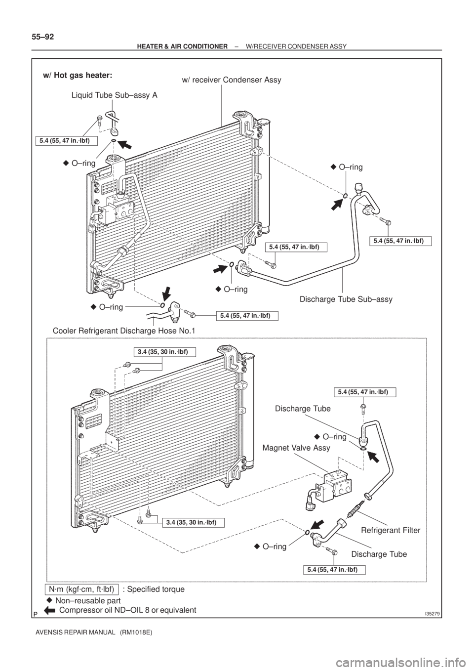
N�m (kgf�cm, ft�lbf) : Specified torque
Non±reusable part �
Compressor oil ND±OIL 8 or equivalentw/ receiver Condenser Assy
Liquid Tube Sub±assy A
Cooler Refrigerant Discharge Hose No.1O±ring �O±ring �
w/ Hot gas heater:
5.4 (55, 47 in.�lbf)
O±ring �
O±ring
�
5.4 (55, 47 in.�lbf)
O±ring �
5.4 (55, 47 in.�lbf)
5.4 (55, 47 in.�lbf)5.4 (55, 47 in.�lbf)
O±ring �
Discharge Tube Sub±assy
5.4 (55, 47 in.�lbf)
3.4 (35, 30 in.�lbf)
3.4 (35, 30 in.�lbf)
Discharge Tube
Discharge Tube
Refrigerant Filter
Magnet Valve Assy
55±92
± HEATER & AIR CONDITIONERW/RECEIVER CONDENSER ASSY
AVENSIS REPAIR MANUAL (RM1018E)
Page 3786 of 5135

14±9
1ZZ±FE,3ZZ±FE ENGINE REPAIR MANUAL
(RM923E)
(g) Remove th")
A62193
Straight Pin Fringe Bolt
A62815
Mesh
A62816
37 9 62
4 8 10 5 1
B08737
± ENGINE MECHANICALPARTIAL ENGINE ASSY (1ZZ±FE/3ZZ±FE)
14±9
1ZZ±FE,3ZZ±FE ENGINE REPAIR MANUAL
(RM923E)
(g) Remove the fringe bolt of camshaft timing gear assembly.
NOTICE:
�Be sure not to remove the other 4 bolts.
�In case of reusing the camshaft timing gear, release
the strait pin locking first, and then install the gear.
20. REMOVE CAMSHAFT TIMING OIL CONTROL VALVE ASSY
(a) Remove the bolt and camshaft timing oil control valve.
21. REMOVE OIL CONTROL VALVE FILTER
(a) Remove the bolt, gasket and oil control valve filter.
22. REMOVE CYLINDER HEAD SUB±ASSY
(a) Using a bi±hexagon wrench 10, uniformly loosen and re-
move the 10 cylinder head bolts, in several passes, in the
sequence shown. Remove the 10 cylinder head bolts and
plate washers.
NOTICE:
�Be careful not to drop washers into the cylinder head.
�Head warpage or cracking could result from remov-
ing bolts in an incorrect order.
23. REMOVE CYLINDER HEAD GASKET
(a) Remove the gasket from the cylinder block.
24. REMOVE OIL PUMP ASSY
(a) Remove the 5 bolts, oil pump and gasket.
Page 3787 of 5135

1ZZ±FE,3ZZ±FE ENGINE REPAIR MANUAL
(RM923E)
25. REMOVE OIL FILTER SUB±ASSY
(a) Using SST")
A62817SST
A62202
Cut Position
A01153
A01456
14±10
± ENGINE MECHANICALPARTIAL ENGINE ASSY (1ZZ±FE/3ZZ±FE)
1ZZ±FE,3ZZ±FE ENGINE REPAIR MANUAL
(RM923E)
25. REMOVE OIL FILTER SUB±ASSY
(a) Using SST, remove the oil filter.
SST 09228±06501
26. REMOVE OIL FILTER UNION
(a) Using a socket hexagon wrench 12, remove the oil filter union.
27. REMOVE ENGINE REAR OIL SEAL
(a) Using a knife, cut off the oil seal lip.
(b) Using a screwdriver with its tip taped, pry out the oil seal.
NOTICE:
After the removal, check if the crankshaft is not damaged.
If there is, mend it with a sandpaper (# 400).
28. REMOVE OIL PAN DRAIN PLUG
(a) Remove the oil pan drain plug and gasket from the oil pan.
29. REMOVE OIL PAN SUB±ASSY
(a) Remove the 14 bolts and 2 nuts.
(b) Insert the blade of SST between the bearing cap sub±as-
sembly and oil pan, and cut off applied sealer and remove
the oil pan.
SST 09032±00100
NOTICE:
Be careful not to damage the oil pan contact surface of the
bearing cap sub±assembly and the oil pan flange.
Page 3791 of 5135

1ZZ±FE,3ZZ±FE ENGINE REPAIR MANUAL
(RM923E)
42. INSTALL OIL PAN SUB")
A62821
Seal Width 4 ± 5 mm
6 mmSeal Packing
A62822
SST
A62817SST
14±14
± ENGINE MECHANICALPARTIAL ENGINE ASSY (1ZZ±FE/3ZZ±FE)
1ZZ±FE,3ZZ±FE ENGINE REPAIR MANUAL
(RM923E)
42. INSTALL OIL PAN SUB±ASSY
(a) Remove any old packing material from the contact sur-
face.
(b) Apply seal packing in the shape of bead (Diameter 3.5
mm ± 4.5 mm(0.1379±0.177in)) consequently as shown
in the illustration.
Seal packing: Part No. 08826±00080 or equivalent
NOTICE:
�Remove any oil from the contact surface.
�Install the oil pan within 3 minutes after applying seal
packing.
�Do not put into engine oil within 2 hours after instal-
ling.
(c) Install the oil pan with the 14 bolts and 2 nuts.
Torque: 9.0 N�m (92 kgf�cm, 80 in.�lbf)
43. INSTALL OIL PAN DRAIN PLUG
(a) Place a new gasket on the oil pan drain plug, and install it.
Torque: 37 N�m (377 kgf�cm, 27 ft�lbf)
44. INSTALL ENGINE REAR OIL SEAL
(a) Apply MP grease to a new oil seal lip.
NOTICE:
Keep the lip off foreign materials.
(b) Using SST, tap in the oil seal until its surface is flush with
the oil seal retainer edge.
SST 09223±15030, 09950±70010 (09951±07100)
NOTICE:
Wipe off extra grease on the crank shaft.
45. INSTALL OIL FILTER UNION
(a) Using a socket hexagon wrench 12, install the oil filter union.
Torque: 30 N�m (306 kgf�cm, 22 ft�lbf)
46. INSTALL OIL FILTER SUB±ASSY
(a) Check and clean the oil filter installation surface.
(b) Apply clean engine oil to the gasket of a new oil filter.
(c) Lightly screw the oil filter into place, and tighten it until the
gasket contacts the seat.
(d) Using SST, tighten it an additional 3/4 turn.
SST 09228±06501
Page 3792 of 5135

14±15
1ZZ±FE,3ZZ±FE ENGINE REPAIR MANUAL
(RM923E)
4")
A30890
A62826
Lot No.
A62816
84 2 59
7 3 1 6 10
A62823
Paint Mark
90�
Front
A62815
Mesh
± ENGINE MECHANICALPARTIAL ENGINE ASSY (1ZZ±FE/3ZZ±FE)
14±15
1ZZ±FE,3ZZ±FE ENGINE REPAIR MANUAL
(RM923E)
47. INSTALL OIL PUMP ASSY
(a) Engage the spline teeth of the oil pump drive rotor with the
large teeth of the crankshaft, and side the oil pump.
(b) Install the oil pump with the 5 bolts.
Torque: 9.0 N�m (92 kgf�cm, 80 in.�lbf)
48. INSTALL CYLINDER HEAD GASKET
(a) Place a new cylinder head gasket on the cylinder block
surface with the Lot No. stamp upward.
NOTICE:
�Pay attention to the installation direction.
�Place the cylinder head quietly in order not to damage
the gasket with the bottom part of the head.
49. INSTALL CYLINDER HEAD SUB±ASSY
HINT:
The cylinder head bolts are tightened in 2 progressive steps.
(a) Apply a light coat of engine oil on the threads and under
the heads of the cylinder head bolts.
(b) Using a bi±hexagon wrench 10, install and uniformly tight-
en the 10 cylinder head bolts with plate washers, in sever-
al passes, in the sequence shown.
Torque: 49 N�m (500 kgf�cm, 36 ft�lbf)
(c) Mark the front of the cylinder head bolt with paint.
(d) Retighten the cylinder head bolts 90� in the numerical or-
der shown.
(e) Check that the point marked bolts are moved at 90 �
angle.
50. INSTALL OIL CONTROL VALVE FILTER
(a) Confirm that the filter is clear.
(b) Install the oil control valve filter to the cylinder head.
(c) Place a new gasket on the bolt, and install it.
Torque: 30 N�m (306 kgf�cm, 22 ft�lbf)
Page 3874 of 5135

AVENSIS REPAIR MANUAL (RM1018E)
BASIC INSPECTION
When the malfunction is not confirmed in the DTC check, troubleshooting \
should be carried out in")
05±14
±
DIAGNOSTICS SFI SYSTEM(1ZZ±FE/3ZZ±FE)
AVENSIS REPAIR MANUAL (RM1018E)
BASIC INSPECTION
When the malfunction is not confirmed in the DTC check, troubleshooting \
should be carried out in all the
possible circuits considered as causes of the problem. In many cases, by carrying out the basic engine check
shown in the following flow chart, the location causing the problem can be found quickly and efficiently.
Therefore, using this check is essential in the engine troubleshooting.
1CHECK BATTERY VOLTAGE
NOTICE:
Carry out this check with the engine stopped and ignition switch off. Reference:
OKNG
Voltage11 V or moreLess than 11 V
NGCHARGE OR REPLACE BATTERY
OK
2CHECK IF ENGINE WILL CRANK
NGPROCEED TO PROBLEM SYMPTOMS TABLE ON PAGE 05±22
OK
3CHECK IF ENGINE STARTS
NGGO TO STEP 6
OK
4CHECK AIR FILTER
(a)Visually check that the air filter is not excessively dirty or oily.
HINT:
If necessary, clean the filter with compressed air. First blow from the inside thoroughly, then blow from the
outside of filter. NGREPAIR OR REPLACE
OK
5CHECK IDLE SPEED (See page 14±1)
NGPROCEED TO PROBLEM SYMPTOMS TABLE ON PAGE 05±22
OK
Page 3878 of 5135

05±175
AVENSIS REPAIR MANUAL (RM1018E)
2 PERFORM ACTIVE TEST BY HAND±HELD TESTER(OPERATION OF OCV)
(a) Connect the hand±held tester to the DLC3.
(b) Start the")
± DIAGNOSTICSSFI SYSTEM (1AZ±FE)
05±175
AVENSIS REPAIR MANUAL (RM1018E)
2 PERFORM ACTIVE TEST BY HAND±HELD TESTER(OPERATION OF OCV)
(a) Connect the hand±held tester to the DLC3.
(b) Start the engine and warm it up.
(c) Turn the ignition switch ON and push the hand±held tester main switch ON.
(d) Select the item ºDIAGNOSIS / OBD/MOBD / ACTIVE TEST / VVT CTRL B1º.
(e) Check the engine speed when operating the OCV by the hand±held tester.
Standard:
Tester operationSpecified condition
OCV is OFFNormal engine speed
OCV is ONRough idle or engine stall
OK Go to step 4
NG
3 READ OUTPUT DTC(CHECK IF DTC OUTPUT RECURS)
(a) Clear the DTC.
(1) Operating the hand±held tester to erase the codes, or disconnecting the battery terminal or the
EFI and ECTS fuses for more than 60 sec.
(b) Start and warm up the engine.
(c) Drive the vehicle around for 10 minutes or more.
(d) Read output DTC using the hand±held tester.
Standard: No DTC output.
HINT:
*: DTCs P0011/59 or P0012/59 is output when a foreign object in engine oil is caught in some part of the
system. These codes will stay registered even if the system returns to normal after a short time. These for-
eign objects are then captured by the oil filter, thus eliminating the source of the problem.
OK VVT SYSTEM OK*
NG