Page 498 of 5135

05±326
± DIAGNOSTICSSFI SYSTEM (1AZ±FSE)
AVENSIS REPAIR MANUAL (RM1018E)
2 PERFORM ACTIVE TEST BY HAND±HELD TESTER(OPERATE OCV)
(a) Connect the hand±held tester to the DLC3.
(b) Start the engine and warm it up.
(c) Turn the ignition switch ON and push the hand±held tester main switch ON.
(d) Select the item ºDIAGNOSIS / OBD/MOBD / ACTIVE TEST / VVT CTRL B1º.
(e) Check the engine speed when operating the OCV by the hand±held tester.
Standard:
Tester operationSpecified condition
OCV is OFFNormal engine speed
OCV is ONRough idle or engine stall
NG Go to step 4
OK
3 CHECK IF DTC OUTPUTS REOCCUR
(a) Clear the DTC.
(1) Operating the hand±held tester to erase the codes, or disconnecting the battery terminal or the
EFI and ETCS fuses for 60 seconds or more.
(b) Start the engine and warm it up.
(c) Drive the vehicle around for 10 minutes or more.
(d) Read output DTC using the hand±held tester.
Standard: No DTC output.
HINT:
*: DTCs P0011 or P0012 is output when a foreign object in engine oil is caught in some part of the system.
These codes will stay registered even if the system returns to normal after a short time. These foreign objects
are then captured by the oil filter, thus eliminating the source of the problem.
OK VVT SYSTEM OK *
NG
Page 499 of 5135
A67528
OCV Signal Waveform1 msec./Division 5 V/
Division
GND
(A)(A) (A)
E11
OC1 +OC1±
±
DIAGNOSTICS SFI SYSTEM(1AZ±FSE)
05±327
AVENSIS REPAIR MANUAL (RM1018E)
4INSPECT ECM(OCV SIGNAL)
(a)Inspection using the oscilloscope.
(b)During idling, check the waveform between the terminals
of the E11 ECM connector.
Standard:
Symbols (Terminal No.)Specified condition
OC1+ (E11±16) ± OC1± (E11±15)Correct waveform is as shown
HINT:
The waveform frequency (A) is lengthened as the engine speed
becomes higher.
NGCHECK AND REPLACE ECM (See page 01±32)
OK
5 INSPECT OIL CONTROL VALVE FILTER
NG REPLACE OIL CONTROL VALVE FILTER
OK
6 INSPECT CAMSHAFT TIMING OIL CONTROL VALVE ASSY(OCV) (See page 10±39)
OK Go to step 8
NG
7 REPLACE CAMSHAFT TIMING OIL CONTROL VALVE ASSY(OCV)
GO
8INSPECT CAMSHAFT TIMING GEAR ASSY (See page 14±240)
OK Go to step 10
NG
Page 500 of 5135
05±328
±
DIAGNOSTICS SFI SYSTEM(1AZ±FSE)
AVENSIS REPAIR MANUAL (RM1018E)
9REPLACE CAMSHAFT TIMING GEAR ASSY (See page 14±240)
GO
10CHECK BLOCKAGE(OCV, OIL CHECK VALVE AND OIL HOLE)
NGREPAIR OR REPLACE
OK
11CHECK IF DTC OUTPUTS REOCCUR
(a)Clear the DTC. (1)Operating the hand±held tester to erase the codes, or disconnecting the batter\
y terminal or the
EFI and ETCS fuses for 60 seconds or more.
(b)Start the engine and warm it up.
(c)Drive the vehicle around for 10 minutes or more.
(d)Read output DTC using the hand±held tester.
Standard: No DTC output.
HINT:
*: DTCs P0011 or P0012 is output when a foreign object in engine oil is caught in so\
me part of the system.
These codes will stay registered even if the system returns to normal after a\
short time. These foreign objects
are then captured by the oil filter, thus eliminating the source of the problem.
OKVVT SYSTEM OK
NG
CHECK AND REPLACE ECM (See page 01±32)
Page 583 of 5135
A76873
8
IGF1 IGT2 IGT1
IGT3 E13
IGT4 I1
Ignition Coil and
Igniter No. 1
P R±W
IGNW±R IE4
LG±B
ECR±B
L±YE13
E13
E13
E139
1110
24 I2
Ignition Coil and
Igniter No. 2
I3
Ignition Coil and
Igniter No. 3
I4
Ignition Coil and
Igniter No. 4W±R
W±RW±R 3
2
14
1
42
2 3
3
3 1
4
4 1 R±B R±B
R±B R±B R±B B±R
W±B
W±B
W±B
W±BW±B W±BW±B
1
N2
Noise Filter
(Ignition)R±B B±R 1
3 Engine Room R/B No. 1 and
Engine Room J/B No. 1
B±G 1A
2
B±G
FL MAIN
Battery Engine Room
J/B No.4I13
Ignition Switch
6
AM2 IG24
(LHD)IP11
(RHD)
B±R
1
1
1 1 2
2 AM2IG2
1B±R
BB
5144
44DH 2
DL 16
IG2
Relay
4A 1
4B 1Engine
Room
R/B No.4
EA1
8R±B
W±BR±BW±B
EF B±R2ECM
W±R
W±R Driver
Side J/B
± DIAGNOSTICSSFI SYSTEM (1AZ±FSE)
05±441
AVENSIS REPAIR MANUAL (RM1018E)
WIRING DIAGRAM
Page 643 of 5135

A66074
A66289
Inside
05±542
±
DIAGNOSTICS ECD SYSTEM(1CD±FTV)
AVENSIS REPAIR MANUAL (RM1018E)
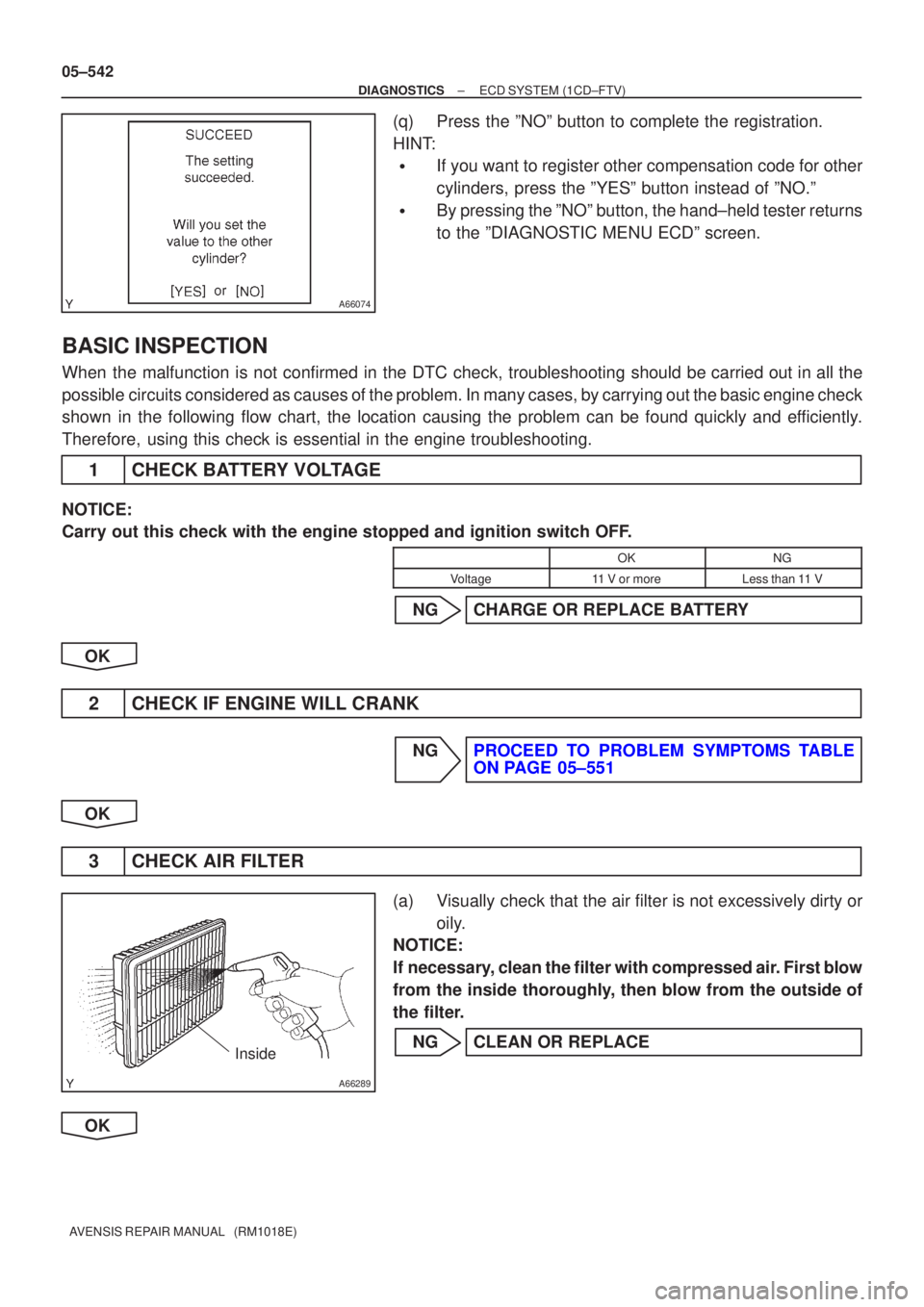
(q)Press the ºNOº button to complete the registration.
HINT:
�If you want to register other compensation code for other
cylinders, press the ºYESº button instead of ºNO.º
�By pressing the ºNOº button, the hand±held tester returns
to the ºDIAGNOSTIC MENU ECDº screen.
BASIC INSPECTION
When the malfunction is not confirmed in the DTC check, troubleshooting shou\
ld be carried out in all the
possible circuits considered as causes of the problem. In many cases, by carrying out the basic engine check
shown in the following flow chart, the location causing the problem can be found quickly and efficiently.
Therefore, using this check is essential in the engine troubleshooting.
1CHECK BATTERY VOLTAGE
NOTICE:
Carry out this check with the engine stopped and ignition switch OFF.
OKNG
Voltage11 V or moreLess than 11 V
NGCHARGE OR REPLACE BATTERY
OK
2CHECK IF ENGINE WILL CRANK
NGPROCEED TO PROBLEM SYMPTOMS TABLE ON PAGE 05±551
OK
3 CHECK AIR FILTER
(a) Visually check that the air filter is not excessively dirty or oily.
NOTICE:
If necessary, clean the filter with compressed air. First blow
from the inside thoroughly, then blow from the outside of
the filter.
NG CLEAN OR REPLACE
OK
Page 1528 of 5135

± DIAGNOSTICSCOMBINATION METER
05±1507
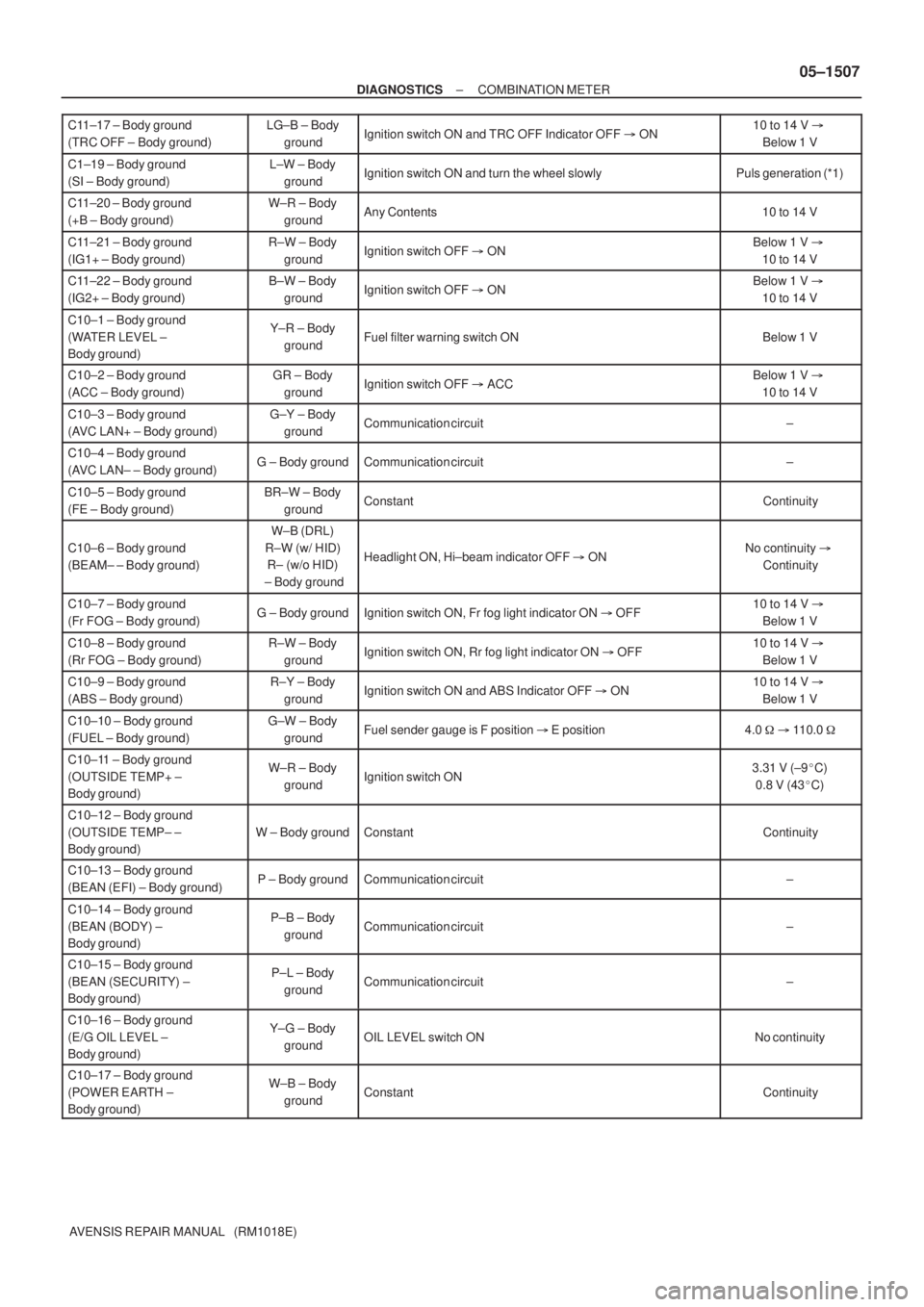
AVENSIS REPAIR MANUAL (RM1018E) C11±17 ± Body ground
(TRC OFF ± Body ground)
LG±B ± Body
groundIgnition switch ON and TRC OFF Indicator OFF � ON10 to 14 V �
Below 1 V
C1±19 ± Body ground
(SI ± Body ground)L±W ± Body
groundIgnition switch ON and turn the wheel slowlyPuls generation (*1)
C11±20 ± Body ground
(+B ± Body ground)W±R ± Body
groundAny Contents10 to 14 V
C11±21 ± Body ground
(IG1+ ± Body ground)R±W ± Body
groundIgnition switch OFF � ONBelow 1 V �
10 to 14 V
C11±22 ± Body ground
(IG2+ ± Body ground)B±W ± Body
groundIgnition switch OFF � ONBelow 1 V �
10 to 14 V
C10±1 ± Body ground
(WATER LEVEL ±
Body ground)Y±R ± Body
groundFuel filter warning switch ONBelow 1 V
C10±2 ± Body ground
(ACC ± Body ground)GR ± Body
groundIgnition switch OFF � ACCBelow 1 V �
10 to 14 V
C10±3 ± Body ground
(AVC LAN+ ± Body ground)G±Y ± Body
groundCommunication circuit±
C10±4 ± Body ground
(AVC LAN± ± Body ground)G ± Body groundCommunication circuit±
C10±5 ± Body ground
(FE ± Body ground)BR±W ± Body
groundConstantContinuity
C10±6 ± Body ground
(BEAM± ± Body ground)
W±B (DRL)
R±W (w/ HID)
R± (w/o HID)
± Body ground
Headlight ON, Hi±beam indicator OFF � ONNo continuity �
Continuity
C10±7 ± Body ground
(Fr FOG ± Body ground)G ± Body groundIgnition switch ON, Fr fog light indicator ON � OFF10 to 14 V �
Below 1 V
C10±8 ± Body ground
(Rr FOG ± Body ground)R±W ± Body
groundIgnition switch ON, Rr fog light indicator ON � OFF10 to 14 V �
Below 1 V
C10±9 ± Body ground
(ABS ± Body ground)R±Y ± Body
groundIgnition switch ON and ABS Indicator OFF � ON10 to 14 V �
Below 1 V
C10±10 ± Body ground
(FUEL ± Body ground)G±W ± Body
groundFuel sender gauge is F position � E position4.0 � � 110.0 �
C10±11 ± Body ground
(OUTSIDE TEMP+ ±
Body ground)W±R ± Body
groundIgnition switch ON3.31 V (±9�C)
0.8 V (43�C)
C10±12 ± Body ground
(OUTSIDE TEMP± ±
Body ground)
W ± Body groundConstantContinuity
C10±13 ± Body ground
(BEAN (EFI) ± Body ground)P ± Body groundCommunication circuit±
C10±14 ± Body ground
(BEAN (BODY) ±
Body ground)P±B ± Body
groundCommunication circuit±
C10±15 ± Body ground
(BEAN (SECURITY) ±
Body ground)P±L ± Body
groundCommunication circuit±
C10±16 ± Body ground
(E/G OIL LEVEL ±
Body ground)Y±G ± Body
groundOIL LEVEL switch ONNo continuity
C10±17 ± Body ground
(POWER EARTH ±
Body ground)W±B ± Body
groundConstantContinuity
Page 1535 of 5135
Terminal No.
Wire harness side
Turn Signal Flasher Relay
Skid Control ECU with Actuator Brake Fluid Level Warning Switch
Engine ECU
Oil Pressure Switch
DOME Fuse Headlight Beam Level Control ECU
Skid Control ECU with Actuator
Skid Control ECU with Actuator Turn Signal Flasher Relay Engine ECU ± Multi Display RAD No.1 Fuse
GND
EMPS ECU
TAIL Fuse
Skid Control ECU with Actuator Fuel Sensor Gauge
Skid Control ECU with Actuator
± GND
Rear Fog Light Relay Front Fog Light Relay Multi Display Fuse Filter Warning Switch (*1)
IGN Fuse Fuel Sender Gauge
Engine Oil Level Sensor Security ECU Ambient Temp. Sensor
4P OUT (Other Parts) H±HI RH Fuse/H±LP RH Fuse 1
2
3
4
5
6
7
8
9
10
11
12
13
14
15
16
17
18
19
201
2
3
4
5
6
7
8
9
10
11
12
13
14
15
16
17
18
C10
Airbag Sensor Assembly GND
GAUGE1 Fuse Skid Control ECU with Actuator
C11Engine ECU
Integration Relay
21
22
*1: 1CD±FTVAmbient Temp. Sensor
± DIAGNOSTICSCOMBINATION METER
05±1505
AVENSIS REPAIR MANUAL (RM1018E)
Page 1912 of 5135
A79150
A79151
A79152
A62166
SST
±
FUEL INJECTION OR SUPPLY PUMP ASSY(1CD±FTV)
11±71
AVENSIS REPAIR MANUAL (RM1018E)
29.REMOVE INTAKE MANIFOLD INSULATOR NO.1
(a)Remove the 2 bolts and the intake manifold insulator.
30.REMOVE OIL LEVEL GAGE SUB±ASSY
31.REMOVE OIL LEVEL GAGE GUIDE(See page 17±22)
32.REMOVE WATER INLET(See page 16±50) 33. DISCONNECT INJECTION PUMP TO FUEL PIPE FUELHOSE
(a) Disconnect the injection pump to fuel pipe fuel hose from the supply pump.
34. DISCONNECT INJECTION PUMP TO FUEL FILTER FUEL HOSE OR PIPE
(a) Disconnect the injection pump to fuel filter fuel hose or pipe from the supply pump.
35. REMOVE INJECTION PUMP DRIVE PULLEY
(a) Using SST, remove the pulley nut. SST 09960±10010 (09962±01000, 09963±01000)